PC Controlled Wireless Notice Board
Kanthimathi ARU1,Kohila S2, Muthu Veni R3 and Kanna P4
1,2,3Assistant Professor, 4PG Scholar, ECE department, Francis Xavier Engineering College, Tirunelveli, Tamilnadu, India.
Article Received: 27 January 2018 Article Accepted: 23 February 2018 Article Published: 15 April 2018
1.INTRODUCTION
Wireless communication is best communication compare to wired communication. By this a long process involved in order to put up the notices on the notice board in the institutions is reduced. Urgent notices displayed immediately and it can be highlighted. In early days, the speed of the Data is controlled only through Wired
Communication. But it is possible to the Data transfer or Receiver of the data from the Wireless Communication. So this paper deals with advanced notice board and time will be displayed on the board. There is a long process
involved in order to put up the notices on the notice board in the institutions. Urgent notices should be displayed immediately and it should be highlighted LED-based displays can be of two types: dot-matrix and segmental. The
ZigBee module is used to receive and transmit the data. ZigBee device is often used in mesh network to transmit data over longer distances for wireless communication.
2.LITERATURE SURVEY
In the work is done on Notice display but PIC16F77A is being used for controlling the system and for display the notice only LCD is used. Zigbee module is connected to the computer via MAX232. A voltage regulator is designed to automatically maintain a constant voltage level. It is used to stabilize the DC voltages used by the
processor and other elements. It is used in the Transmitter section to stabilize the voltage at the output of MAX232 before passing it to Zigbee Module. Zigbee module on the receiver side is interfaced with UART (Universal
Asynchronous Receiver/Transmitter) of Micro-Controller PIC16F877A. Micro-Controller receives the message from Zigbee module on receiver side and displays it on the LCD screen. It also provides Synchronization between
Transmitter and Receiver. In digital learning display has designed especially for the children in rural areas from which they can learn Bengali and English alphabet and numbers. The display is formed cascading twelve 8X8 dot
matrix displays so that the designed character patterns are attractive to the children. It can be controlled by an IR remote. Only a 12V DC battery is enough to drive the display. The power consumption of the display is very low.
So, schools at remote area where electricity is not available can easily use this display to make the learning more A B S T R A C T
Notice board is primary thing in any institution or organization or public utility places like bus stops, railway stations or parks. But sending various notices day to day is a tedious process. In our proposed system, we proposed model of wireless notice board displays the time. When there is interrupt of message time disappears and message starts scrolling. It uses Zigbee modules on the transmitter side, transmit message from PC to the display board. The information send from PC is stored in EEPROM of Arduino board, which is received by zigbee. Dot matrix display is used in system to display the information received by zigbee on receiver side on notice board. This project has various scopes in hospital, industries, Educational institute where very important notices are made in large basis.
enjoyable to the children. An 8-bit PIC microcontroller is used to control the display and generating different character patterns. This is our first attempt to make the learning interesting for the children.
3.PROPOSED SYSTEM
As the wireless technology is introduced in the world it makes the huge flowering and impetus over the past few years‟ importunity of wireless technology is increased in industrial and domestic functioning. This project uses the
wireless communication, Zigbee. The Zigbee transmitter will be present at the Principal or the person related to the issues to be displayed on the notice board. PC keyboard is used as the input device here in this project. Whenever
the user wants to send the news updated to the notice board, he types that particular message using keyboard and the same data will be transmitted through Zigbee transmitter.
At the receiving end, the Zigbee receiver and the decoder will be fixed to the display panel. The receiver receives
the data coming from the transmitter and the same data will be received by the microcontroller at the receiver end. The microcontroller sends this data to the display unit and thus the message given by the user at the transmitter end will be displayed.
Fig.1 Arduino Uno
From all the above we are recommending only number of Transmitter and single receiver system due to lack of availability of displays and even cost matters. Arduino is a single-board microcontroller to make using electronics
in multidisciplinary projects more accessible. The hardware consists of a simple open source hardware board designed around an 8-bit Atmel AVR microcontroller, or a 32-bit Atmel ARM. Signals are omnipresent of course
the system is working under wireless technology.
So there is no need of cables and wires. In case, the system will become cost efficient also there will be less handling required for the system. It also increases neatness of region sand standard of organization .Time required
Fig. 2 Block diagram for transmitter side
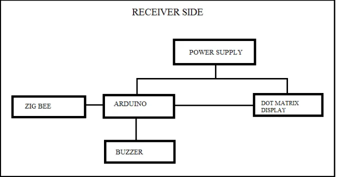
Fig. 3 Block diagram for receiver side
4.BLOCK DIAGRAM DESCRIPTION
Message from PC is sended to zigbee on transmitter side. Receiver zigbee sense the signal and send information to Arduino. Arduino is being used for controlling the system receives the message from Zigbee module on receiver
side and displays it on the DMD Board. It also provides Synchronization between Transmitter and Receiver. Zigbee module is connected to the computer. DMD has inbuilt shift register in it which controls the blinking of LEDs in rows and columns. Now the signal will enter into the receiving portion after transmitting from the
transmitter, receiver side consist of zigbee module at the starting of the notice board as it is indicated already in block diagram. After that zigbee will sends signal to microcontroller. Microcontroller will gives respond to the
signal which is transmitted by zigbee to microcontroller, now microcontroller decode the commands and send it reliably to the next step. Our next step is display board where the commands are display after the whole process.
After passed commands from microcontroller to notice board the components inside the notice board gate accessed to performed task glow the LEDs. Hence in such way system starts running. Zigbee is used to receive the data from
5.USED HARDWARE AND SOFTWARE
1. Zigbee Transceiver Module 2. Arduino board
3. Dot matrix Display 4. Power supply
5. Buzzer 6. Ardino1.8.5
7. Proteus for simulation
6.DISPLAY BOARD
Fig.4 16X32 White LED dot matrix display
There is a long process involved in order to put up the notices on the notice board in the institutions. Urgent notices should be displayed immediately and it should be highlighted. In this digitalized era in the institutions the notices are still displayed in the board and required paper work. Sometimes the 38 important notice are missed which
should be known immediately. Whereas the LED displays are widely used in Public areas for various type of display, because of large screen, long life and flexible display. The proposed system is very useful is this area. It can
announce a notice just by typing on a computer in the application window. The LED matrix board contains 16 rows and 64 columns of LEDs; the display has 1024 LEDs in a 16x64 grid. Also, dot matrix displays are popularly
referred to by their matrix size, that is, the number of LEDs on a row and on a column. Glowing of LED varies for each character depending upon the font size of the sending information to the display board. The pattern
arrangement of LEDs is similar to the pixel dots of the typical cathode ray tube. Thus, any character formed by lighting the appropriate dot on the display. These appropriate dots for the character are known as its display pattern.
6.1. FEATURES
1. 32 x 16 high brightness white LEDs (512 LEDs total) on a 10mm pitch.
2. 5V operation.
3. Viewable over 12 meters away. 4. Tough plastic frame.
6. Arduino compatible library, graphics functions and example support.
7. Dimensions: 320(W) x 160(H) x 14(D) mm (30mm (D) including rear connectors.
7.RESULTS AND DISCUSSIONS
a. Software Result
The open-source Arduino Software (IDE) makes it easy to write code and upload it to the board. It runs on
Windows, Mac OS X, and Linux. The environment is written in Java and based on Processing and other open-source software. This software can be used with any Arduino board. All the Arduino 00xx versions are also
available for download. The Arduino IDE can be used on Windows, Linux (both 32 and 64 bits), and Mac OS X Active development of the Arduino software is hosted by GitHub. The archives are PGP-signed so they can be
verified using this gpg (GNU privacy guard) key. This explains how to connect your Uno board to the computer and upload your first sketch. The Arduino Uno is programmed using the Arduino Software (IDE), our Integrated
Development Environment common to all our boards and running both online and offline.
Fig.5 Opening a new Project in Arduino software
As we using a serial board, power the board with an external power supply (6 to 12 volts DC, with the core of the connector positive). Connect the board to a serial port on the computer. On the USB boards, the power source is
selected by the jumper between the USB and power plugs. To power the board from the USB port (good for controlling low power devices like LEDs), place the jumper on the two pins closest to the USB plug. To power the
board from an external power supply (needed for motors and other high current devices), place the 52 jumper on the two pins closest to the power plug. Either way, connect the board to a USB port on your computer. 16X32 White
LED dot matrix display.
Fig.7. Application window
Application window appear after compilation of compiling processing Arduino window. It is used to send
information to required destination by Zigbee from pc to notice board. The information will be type in different format. It consists of clear output option which clears the previous information transmits from the authority. This
application window appears only when the Zigbee or Arduino USB connecting to the PC. Following steps are taken to connect Arduino board.
1. Selection of board type
2. Select your board type and port
3. We will need to select the entry in the Tools > Board menu that corresponds to your Arduino or Genuino
board.
7.1 HARDWARE MODEL
This project uses the wireless communication, Zigbee. The Zigbee transmitter will be present at the Principal or the
person related to the Issues to be displayed on the notice board. PC keyboard is used as the input device here in this project. Whenever the user wants to send the news updated to the notice board, he types that particular message
using keyboard and the same data will be transmitted through Zigbee transmitter. At the receiving end, the Zigbee receiver and the decoder will be fixed to the display panel. The receiver receives the data coming from the transmitter and the same data will be received by the microcontroller at the receiver end. The microcontroller sends
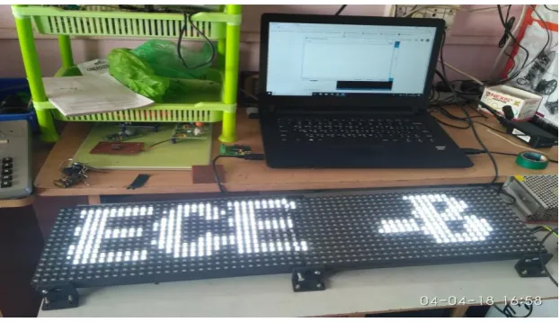
Fig 8. Hardware display of wireless notice board
8.CONCLUSION
The implemented proposed system will be very useful for urgent notice. The developed application window is used
to write the notice so that when anything is written on that window it display immediately on the board after pressing the „send‟ button. With the help of this system notices can be transmitted from any computer if needed, it
only requires extra Zigbee module. After the installation process, it is easy to use and notices can be changed at any time. Authentication to different authority can be provided for security purpose. This system is very useful for
urgent notices.
REFERENCES
[1] Ajinkya Gaikwad and Tej Kapadia, “Wireless Electronic Notice Board,” International Journal on ACTE,
International Journal on Advanced Computer Theory and Engineering (IJACTE), vol. 2, Issue 3, pp. 1-4, 2013.
[2] Muthukumaran. N and Ravi. R, 'Hardware Implementation of Architecture Techniques for Fast Efficient
loss less Image Compression System', Wireless Personal Communications, Volume. 90, No. 3, pp. 1291-1315, October 2016, SPRINGER.
[3] Muthukumaran. N and Ravi. R, 'The Performance Analysis of Fast Efficient Lossless Satellite Image Compression and Decompression for Wavelet Based Algorithm', Wireless Personal Communications,
Volume. 81, No. 2, pp. 839-859, March 2015, SPRINGER.
[4] Muthukumaran. N and Ravi. R, 'VLSI Implementations of Compressive Image Acquisition using Block
Based Compression Algorithm', The International Arab Journal of Information Technology, vol. 12, no. 4, pp. 333-339, July 2015.
[6] Ruban Kingston. M,Muthukumaran. and N, Ravi. R, 'A Novel Scheme of CMOS VCO Design with reduce number of Transistors using 180nm CAD Tool', International Journal of Applied Engineering Research,
Volume. 10, No. 14, pp. 11934-11938, 2015.
[7] M.A. Kader, Md. Mahbubur Rahman, “LED Matrix Based Digital Learning Display for Children With Wireless Control,” 17th International Conference on Computer and Information Technology
(ICCIT),International Islamic University Chittagong (IIUC) Chittagong, Bangladesh, pp. 397-400, April
2014.
[8] Muthukumaran. N and Ravi. R, 'Design and analysis of VLSI based FELICS Algorithm for lossless Image
Compression', International Journal of Advanced Research in Technology, Vol. 2, No. 3, pp. 115-119, March 2012.
[9] Manoj Kumar. B and Muthukumaran. N, 'Design of Low power high Speed CASCADED Double Tail Comparator', International Journal of Advanced Research in Biology Engineering Science and
Technology, Vol. 2, No. 4, pp.18-22, June 2016.
[10] N. Muthukumaran, 'Analyzing Throughput of MANET with Reduced Packet Loss', Wireless Personal Communications, Vol. 97, No. 1, pp. 565-578, November 2017, SPRINGER.
[11] P.Venkateswari, E.Jebitha Steffy, Dr. N. Muthukumaran, 'License Plate cognizance by Ocular Character Perception', International Research Journal of Engineering and Technology, Vol. 5, No. 2, pp. 536-542,
February 2018.
[12] N. Muthukumaran, Mrs R.Sonya, Dr.Rajashekhara and Chitra V, 'Computation of Optimum ATC Using
Generator Participation Factor in Deregulated System', International Journal of Advanced Research Trends in Engineering and Technology, Vol. 4, No. 1, pp. 8-11, January 2017.
[13] Keziah. J, Muthukumaran. N, 'Design of K Band Transmitting Antenna for Harbor Surveillance Radar Application', International Journal on Applications in Electrical and Electronics Engineering, Vol. 2, No. 5,
pp. 16-20, May 2016.
[14] Akhil. M.S and Muthukumaran. N, 'Design of Optimizing Adders for Low Power Digital Signal
Processing', International Journal of Engineering Research and Applications, Vol. 5, pp. 59-65, March 2014.
[15] Shih-Mim Liu and Yan-Chi Chou, “Color Calibration for a Surrounding True-Color LED Display System by PWM Controls,” IEEE Transiction on Electronics, vol. 61, no.11, pp. 6244-6252, Nov 2014.
[16] N.B.Bhawarkar and G.V. DehankarȦ, “ARM Based Electronic Notice Board through Zigbee with Room Lights Control using PIR Sensor,” International Journal of Current Engineering and Technology, vol 4,
no.2, pp. 753-756, April 2014.
[17] Pawan Kumar, Vikas Bhardwaj, Narayan Sing Rathor, Amit Mishra, GSM Based e-Notice Board:Wireless Communication. ISSN: 2231-2307, Volume-2, Issue-3, July 2012
[18] Muthukumaran. N and Ravi. R, 'Quad Tree Decomposition based Analysis of Compressed Image Data Communication for Lossy and Lossless using WSN', World Academy of Science, Engineering and
[19] Marvin Mark. M and Muthukumaran. N, 'High Throughput in MANET using relay algorithm and rebroadcast probability', International Journal of Engineering Research and Applications, Vol. 5, pp.