OPTIMIZATION OF AA7075 AUTONOMOUS UNDERWATER
VEHICLE (AUV) PROPELLER FRONT HUB PRE-FORM SIZING
FOR FLASH-LESS COLD FORGING PROCESS – A FE STUDY
V.Komalapur1, H.M.T.Khaleed2, H.Udayaprasanna3 & Abdulgafur A41. INTRODUCTION
Forging is a deformation process of materials through compressive stress which indicate the important results carried out in hot and cold modes, with latter producing good surface finish, high strength and greater accuracy [1-2]. Cold process design adopts process layout methodology due to variety of work procedures and complexity making it difficult to proceed without designer’s expertise [3]. Customers need for complex three-dimensional product along with prediction of the complicated phenomena to monitor tool life, ductile fracture and microstructure. The design process should account for these parameters considering new materials and advanced processes available for adoption[4]
The computer aided analysis of the forging process design has advanced remarkably to overcome difficulties in the recent design environment [5].
Autonomous underwater vehicle (AUV) is a battery or fuel cell powered robotic device driven by a propulsion system controlled and piloted through computer programme interfaced to navigation sensors such as inertial measurement unit, sonar sensor, laser rangers and pressure sensors to facilitate maneuverability [6]. AUV have made a revolution in ocean research during last two decades that transformed heavy and expensive equipment for ocean academic research into a tool for solving wide range of issues in theoretical and practical arena that includes commercial and military applications [7]. The common propulsion technique used in AUV propeller powered thrusters through various other designs is evolving out [8]. These propellers generally can be manufactured by casting [9-10] and machining that face inherent on part strength and surface finish that usually require machining to get desired quality [11]. The addition flaws arising out of thermal problems have to be solved and grain structure has to be controlled. In machining process involves constraints like collision between tool and work-piece, material wastage, tool vibration and uncontrolled grain structure [12]. The strength of the propeller manufactured by casting was reported to be 17% lesser compared to long glass fibre reinforced polyamide thermoplastic [13]. The propeller material selection is based on engine horsepower, for example composite and bronze propellers are used on engines of less than 50 hp, whereas aluminum propellers are adopted for engines of up to 150 hp. The demerit of composite propellers
1
School of Mechanical Engineering, KLETECH University, Hubballi, Karnataka, India 2Department of Mechanical Engineering, Islamic University, Madinah, K.S.A
3
Department of Mechanical Engineering, AITM, Bhatkal, Karnataka, India 4
Department of Mechanical Engineering, AITM, Bhatkal, Karnataka, India
DOI: http://dx.doi.org/10.21172/1.93.24
e-ISSN:2278-621X
includes non-reparability and size limitation to produce small propeller [14]. Aluminum propellers are expensive than composites, through most of them are better in terms of corrosion resistance and strength [15]. AA 7075 alloy is motivating material having mechanical properties low density, high strength, moderate ductility and toughness. These alloys used for highly stressed structural applications like gear, shaft, regulating valve and various part of aerospace vehicles and marine applications [16].
Literature available on manufacture AUV propellers and other propellers using cold forging is limited [17]. This study analyzes process and design of cold forging die as per the dimensions of designed geometry using FEM technique. The researches have been done on manufacturing of AUV propeller by different manufacturing processes but propeller manufacturing by cold forging process and specifically using different material to achieve high strength and thrust is still acking. In this paper AL 7075 material is used and optimized the preform of front hub and comparative study has been done with AL 6061.
2. METHODOLOGY
This section deals with methodology adopted for implementation of finite element approach for the analysis of flash-less cold working in AUV propeller manufacture.
2.1 FE Formulation –
The studies on cold forging do not account elastic deformation due to large in process deformation and behavior of work material as rigid plastic. In this study, analysis of deformation was determined by the rigid-plastic FE technique (AFDEX built-in function) [18]. The pre-form was assumed to obey the Von-mises yield criterion and its associated flow rule, the stress and strain field solutions satisfy the equilibrium equations. The equations related to rigid-plastic FE are as follows [19]: Equilibrium Equation:
Boundary conditions:
σijni FjonSF,ui Ui on SU (4)
ni - Materials rate of formability change; Fj - force on boundary surface SF ; ui -deformation velocity on boundary surface
SU
SF - Surface on which force applied;SU - deformed surface
The functional mathematical equation for rigid plastic [20] Π σ
dV-SF tividS (5)
ti - Traction specified on the boundary SF ; vi - velocity component; dV and dS – volume and surface area of material Considering a penalty constant K and modifying equation 5, the incompressibility constraints on admissible velocity fields can be removed. Thus the solution of boundary value problem is obtained from the solution of the dual variation problem, where the first order variation of the functional vanishes.
Π σ��dV t�vdS K � �� dV 0 i i v v v SF v � � � � � � � � � (6)
Where vi - arbitrary variation; and v- variations in strain rate from vi, vis the volumetric strain rate
2.2. Pre-form Dimensional Analysis–
Pre-form specifications can be obtained by assumption, volume of finished product and initial raw material must be same [21]. The volume of the finished product and pre-form specifications can be calculated theoretically and through SOLIDWORKS. The next step was to obtain optimum specification of the form in terms of front hub, the cylindrical pre-form length L and larger circle radius r . Equating the pre-pre-form volume and finished volume:
Where r represents smaller circle radius, A , A- Area of larger and smaller circle of pre-form.
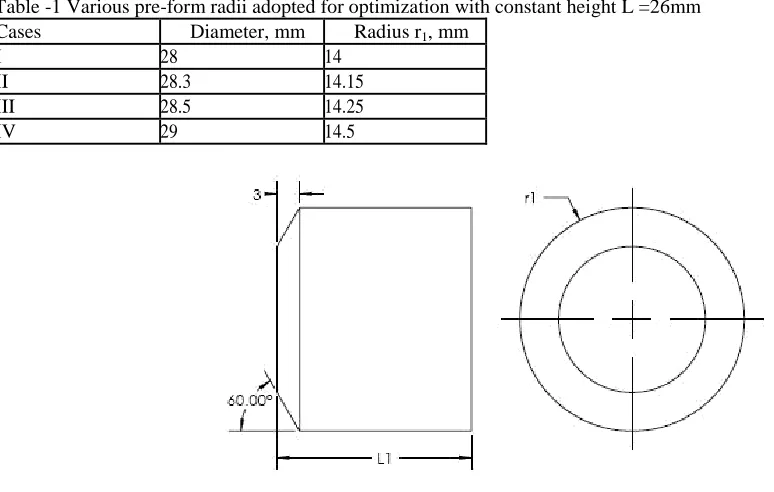
Based on equation (10), using AFDEX optimal pre-form was obtained by varying radius r with L kept constant at 26 mm as indicated in figure 1 and table 1. The iterations were performed until finished dimensions, flash and under-fill satisfactory to the specified application was achieved.
Table -1 Various pre-form radii adopted for optimization with constant height L =26mm
Cases Diameter, mm Radius r1, mm
I 28 14
II 28.3 14.15
III 28.5 14.25
IV 29 14.5
Figure 1. Geometry of AUV propeller
2.3. Finite Element Modelling and Material Specification –
The Punch, die, pre-form and finished front hub were modeled using SOLIDWORKS to obtain the geometry in STL file format that later was taken as an input to AFDEX. The discretization involved number of elements for punch/die as 50500 while for the pre-form 20000 elements of tetrahedral element type were used. The process parameter considered for analysis included: initial temperature of pre-form, punch and die temperature(25°C), punch velocity (250mm/s), friction co-efficient (0.15), punch stroke (8 mm), pre-form material AA 7075 and punch/die material AISI D2. Material properties for pre-form die and punch:
Table -2 Workpiece, punch and die material properties selected for optimization studies
Parameter Pre-form Die/Punch
Material type AA 7075 AISI D2
Young’s modulus, GPa 70 210
Yield strength, MPa 503 2200
Poisson ratio 0.33 0.33
Hardness, Rockwell A, HRC 53.5 62
3. RESULTS AND DISCUSSION
This section deals with results obtained with respect to volumetric analysis of pre-form geometry and dimensional accuracy.
3.1 Geometry Optimization of Pre-form –
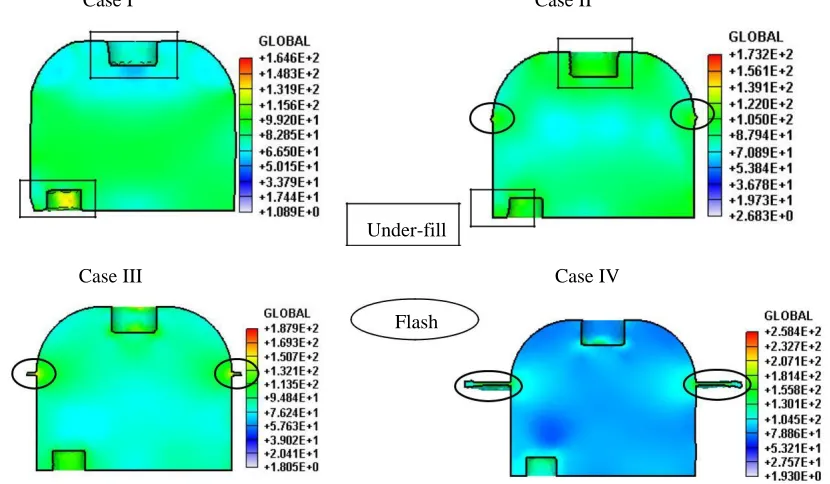
The vital concern of the present work was to eliminate under-filling and minimize flash and forge load, This objective of research was addressed through simulations using AFDEX for selected pre-form to achieve optimum pre-form geometry. The simulations indicated that due to higher volume of the pre-form considered to ensure no under-filling lead to small amount of flash proportional to this excess volume. Thus with no under-filling achieved resulting flash was observed and minimized as indicated in Table 3 for various specimens. Case I indicated deformation without any flash with about 1.36 % of under-fill. Case II resulted with 0.81% flash with under-fill and case III and IV showed deformation without under-fill with respectively 2.21 % and 5.61 % of flash. The study concluded that case III geometry was the best option and was hence considered for further investigation.
Table -3 AFDEX simulations for pre-form, die cavity volume and % of flash
Case Pre-form Die cavity volume, Pre-form Pre-form volume, Flash Volume, Under-filling % of
height, mm mmᶾ diameter, mm mmᶾ (mmᶾ) (mmᶾ) flash
I 28 15408.76 NF 210.66 0%
II
26 15619.42
28.3 15748.32 128.90 UF 0.81%
III 28.5 15973.39 353.97 NUF 2.21%
IV 29 16548.24 928.82 NUF 5.61%
NF – No flash; UF – Under fill; NUF-No under-filling
3.2 Effect of Pre-form geometry on Simulation –
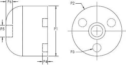
The propeller front hub dimensional accuracy of component with various pre-form geometries were simulated for four different cases as shown in figure 2 and table 4.
Table -4 Dimensional deviation analysis with respect to geometric entities
P1 P2 P3 P4 P5 P6
Dimension, mm 25.00 30.00 5.00 3.00 7.00 4.00
Design tolerance, mm ±0.15 ±0.25 ±0.1 ±0.10 ±0.15 ±0.10
Geometric entity P1 P2 P3 P4 P5 P6
Case I
AFDEX, Dim., mm 24.79 29.81 4.92 2.66 6.82 3.52
Deviation, mm 0.21 0.19 0.08 0.34 0.18
0.48
Case II
AFDEX, Dim., mm 25.00 29.88 4.95 2.96 6.95 3.91
Deviation, mm 0.00 0.12 0.05 0.04 0.05 0.09
Case III, IV
AFDEX, Dim., mm 25.00 29.97 4.98 2.98 6.97 4.03
Deviation, mm 0.00 0.03 0.02 0.02 0.03 0.03
Cases I, II, III and IV as indicated in table 4 exhibited greater dimensional deviations with respect P1, P2, P3, P4, P5 and P6 geometrical entities of the component. The case I indicated dimensional deviation beyond the tolerance limit with respect to P3 to P6. However case II, III and IV provided acceptable dimensional deviations with respect to all six geometric entities. Case III resulted in acceptable deviations for all six geometric entities of the component as shown in figure 3. However, by superimposing the results of section A it was concluded that case III pre-form parameter be taken up for further analysis.
Case I Case II
Under-fill
Case III Case IV
Flash
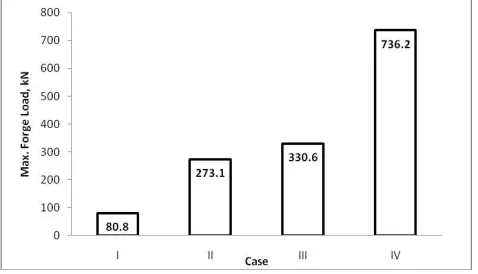
3.3 Effect of Parameters Variation on Forging Load –
The pre-form parameter variations influenced the load required to forge components as indicated by simulation results from AFDEX tool. The figure 4 depicts load predictions for Cases I to IV as presented in section B. The results from post processor provided the maximum magnitude of values of loads for each of the cases with respect to the maximum predicted forging load was 736 kN for case IV. Case I, II and III had relatively lower magnitude of maximum load recorded as 80.8 kN, 273.1 and 330.6 kN respectively but occurrence of under-fill was the deterring factor to opt for pre-form I and II. The selection of forging load was trade-off between under-fill and flash. Case IV indicated highest maximum forge load of 736.2 kN amongst the four simulated pre-forms and the results clearly justified choice of case III owing to lower maximum load coupled to flash-less operation without under-fill.
Figure 4. Predicted maximum forge load
3.4 Die stress Analysis –
The stress analysis was carried out for all four pre-forms with respect to stress distribution. It was observed that the maximum stresses occurred at front edge of the punch for case I,whereas case II, III and IV had higher stress levels at curved surface of the top ejector as shown in figure 5. It was also observed that an increase in forge load lead to increase in punch and die stress as revealed by the maximum stress magnitude of 2212 MPa observed in case III considered to be optimum pre-form as shown in figure 6. The increase in effective die stresses beyond the permissible limit of die-material leads to plastic deformation of die that affected dimensional accuracy of die and in turn the forged components. All effective die-stresses in the investigation were within allowable limit of die-material and hence the designed forge load was considered safe for the cold working process. Case IV indicated highest maximum die stress of 3759 MPa among the four simulated pre-forms. However by considering the results of section A, section B and section C it was fulfilled that case III pre-form be taken up for further analysis.
Case Punch stress, MPa Die stress, MPa
I
III
IV
Figure 5. Maximum punch and die stress analysis of various cases
Figure 6. Maximum stress prediction on punch and die
3.5 Comparision with AA 6061 Pre-form–
The design and optimization of AUV propeller front hub was carried out by cold forging considering pre-form AA 6061, the research resulted in optimal pre-form, approving geometrical deviation and permissible stress limit [21-22]. However AA 6061 was less hard compared to AA 7075 in terms of hardness number. This study focused on AA 7075 material which has high strength, stress resistant, workability and improved stress-corrosion cracking resistance and highest strengths of all aluminum alloys [23]. The major enhanced mechanical properties in AA 7075 as compared with AA 6061 was hardness Rockwell A -53.5 (40), yield strength 503Mpa (276MPa) and modulus of elasticity 70 GPa (68.9 GPa)[24]. Table 5 shows material properties on pre-form that increased when compared to AA 6061 due to high hardness and other improved mechanical properties.
Table -5 Properties compared with AL 6061
Properties AA 6061 AA 7075
Density, g/cc 2.7 g/cc 2.81 g/cc
Hardness, HRC 40 53.5
Ultimate Tensile Strength, MPa 310 572
Tensile Yield Strength, MPa 276 503
Modulus of Elasticity, GPa 68.9 71.7
4. CONCLUSION
The FE analysis of the AUV propeller pre-form, die and punch used for cold working indicated the following observations. FE Simulation of AA 7075 and AA 6061 AUV Propeller front hub for Flash-less cold forging without under-fill process simulated using AFDEX, which provided useful results to obtain the better optimal pre-from shape. The four constant length pre-forms with different diameter were considered and evaluated with respect to under-fill and flash. The results indicated that case III found to favorable with respect to flash, zero under-fill, minimum forging load and die stress. AA7075 declared better result as compared to AA 6061 with respect to strength, hardness, toughness and high corrosive resistance. Proposed study was a breakthrough in CAE domain for complex geometries of propeller hubs. Further potential extension to this study can cover the experimental validation, die stress analysis and optimization punch/die to enhance their life.
5. REFERENCES
[1] N. Ishinaga, ―An advanc.ed press design∗ for cold forging‖ Journal of Materials. Processing Technology 71, IOO- 1041997.
[2] Jun Yanagimoto, Sumio Sugiyama , Akira Yanagida, Nobuhiro Iwamura, Motoi Ishizuka. Control of ultrafine microstructure by single-pass heavy deformation and cold forging of metal. journal of materials processing technology. 2 0 9, 679–685,2009.
[3] Xianhong, Yinghong, Xueyu Ruan, A web based cold forging process generation system. Journal of Material Processing Technology 145,
[4] Soo-Young Kim∗, Satoshi Kubota, Masahito Yamanaka. Application of CAE in cold forging and heat treatment processes for1–6,2004.
manufacturing of precision helical gear part. Journal of materials processing technology 2 0 1, 25–31, 2008.
[5] Q. Zhang, E. Felder, S. Bruschi. Evaluation of friction condition in cold forging by using T-shape compression test. Journal of Materials Processing Technology 209, 5720–5729, 2009.
[6] Paul G. Fernandes, Pete Stevenson, Andrew S. Brierley, Frederick Armstrong, and E. John Sim monds. Paul G. Fernandes, Pete Stevenson, Andrew S. Brierley, ICES Journal of Marine Science, 60, 684–691,2003
[7] Salimzhan A, Gafurov, Evgeniy V Klochkov. Atonomous unmanned under water vehicles development tendencies. Procedia Engineering 106, 141-148, 2015.
[8] Brian David Rutkay. A Process for the Design and Manufacture of Propellers for Small Unmanned Aerial Vehicles- thesis, 2014.
[9] Ono S, Saito M, Matsuo S. Microstructure and mechanical properties of 18 mass% chromium cast stainless steel for marine propeller. J. Jap. Inst. Metallurgy, 57(7) (1999) 761-766.
[10] Ganesh D, Jain M, Singh PP, Radhakrishnan KK, Bhattacharya B. Pressure casting of composites propellant, Ind. J. Chem. Technol., 15(4) (2008) 420-423.
[11] Kuo HC, Dzan WY. The analysis of NC machining efficiency for marine propellers, J. Mater. Process Technol., 124(3) (2002) 389-395.
[12] Samad Z, A B Abdullah, H. M. T. Khaleed, M H Abu-Bakar, M R Arshad. A novel manufacturing method of propeller for autonomous underwatwer vehicle (auv) using cold forging. Indian journal of Geo Marine Sciences. Vol.41(3), (2012) 242-248.
[13] Marsh G. A new start for marine propellers. Reinforced Plastics, 48(11) (2004) 34-38.
[14] Tang CH, Cheng FT, Man HC. Laser surface alloying of a marine propeller bronze using aluminum powder: Part II: Corrosion and erosion–corrosion synergism, Surface Coatings Technol., 200(8) (2006) 2594-2601.
[15] Mukhopadhyay SK, Basu J, Chaulia PK. Strength analysis of an aluminum-alloy component of circular geometry developed by cold forming and friction welding method. J. Sci. Ind. Res., 65(3) (2006) 227-231.
[16] Tareg S. Ben Naser, György Krallics. Mechanical Behavior of Multiple-forged Al 7075 Aluminum Alloy. Acta Polytechnica Hungarica. Vol. 11 (2014) 7.
[17] A. B. Abdullah, S. M. Sapuan, Z. Samad, H. M. T. Khaleed and N. A. Aziz. Manufacturing of AA6061 propeller for AUV application using cold forging process. Scientific Research and Essays Vol. 7(2) (2012) 170-176, 16.
[18] Kim, Y.S.; Son, H.S.; Kim, C.I.: Rigid-plastic finite element simulation for process design of impeller hub forming. J. Mater. Process Technology. 143–144 (2003) 729–734.
[19] Kim, D.J.; Kim, B.M.: Application of neural network and FEM for metal forming processes. Int. J. Mach. Tools Manuf. 40(6) (2000) 911–925. [20] Kim, D.J.; Kim, B.M.; Choi, J.C.: Determination of the initial billet geometry for a forged product using neural networks. J. Mater. Process. Technol.
72, (1997) 86–93.
[21] H.M.T. Khaleed , Z. Samad, A.R. Othman, M.A. Mujeebu, A.B. Abdullah, M.M. Zihad. Work-piece optimization and thermal analysis for flash-less cold forging of AUV propeller hubs — FEM simulation and experiment. Journal of Manufacturing Processes 13 (2011) 41–49.
[22] H. M. T. Khaleed , Z. Samad · A. R. Othman · M. Abdul Mujeebu · A. Badarudin · A. B. Abdullah · A. R. Ab-Kadir · Irfan Anjum Badruddin · N. J. Salman Ahmed. Computer-Aided FE Simulation for Flashless Cold Forging of Connecting Rod Without Underfilling. 41–49. Arab J Sci Eng (2011) 36:855–865.