APPLICATION OF DSTATCOM FOR HARMONICS
ELIMINATION AND POWER QUALITY IMPROVEMENT
Ashish A Patel
1, Batavale Karan
2, Kapadia Abhishek
3, Chudasama Ruchit
4, Dhimmar Gaurang
5and
Kulkarni Bhagyesh
6I. INTRODUCTION
Non-sinusoidal components in power system is mainly due to non-linear behavior of devices such as transformer tap-changer, adjustable speed drive, switch mode power supply, renewable energy source, HVDC system and other non-linear loads. In most of cases, non-linear loads are interpreted either as harmonic current source or a harmonic voltage source in practice [1]. Power healing is required for improvement of power quality which includes harmonic elimination, reactive power compensation, voltage regulation, load balancing etc. Enhancement in features of the active filter used in distribution system is known as Custom Power Device. An improved version of a shunt active filter named as DSTATCOM is used for degradation of current related power quality issues. The major advantages of DSTATCOM are better response and capacity for transient overload even at voltage sag. IEEE 519 and IEC are used as guideline of harmonic limits at point of common coupling [2]. Efficient utilization of voltage source converter (VSC) used as a DSTATCOM depends upon the control algorithm used for finding reference currents and switching pattern. Many time-domain control algorithms are available based on phase-dictated sinusoidal tracking, extraction of non stationary sinusoidal and non-linear time frequency analysis, direct power control and other soft computing algorithms etc for extracting reference signals [3-5]. The field of adaptive control has been made for control algorithms, design techniques and analytic tools. It is closed loop system that can adjust system behavior during any kind of disturbances. Based on this control theory, many control algorithms are also reported in available content such as improved adaptive detection algorithm for selective harmonics detection, adaptive filter for synchronous extraction etc [6,7].
In this paper, an adaptive filter based control algorithm is implemented in a three-phase distribution system for reactive power compensation and harmonic elimination. Main features of this control technique are high convergence speed, robustness with respect to input frequency variation and internal parameter variation, less sensitive to voltage fluctuation. Construction of this control algorithm is based on basic arithmetic operation due to this reasons-simple implementation and no need of extra synchronization circuit.
II. PROPOSED ALGORITHM A. Configuraton of DSTATCOM:
1Department of Electrical Engineering,S. N. PATEL INSTITUTE OF TECHNOLOGY & RESEARCH CENTRE, UMRAKH, Bardoli
2Department of Electrical Engineering,S. N. PATEL INSTITUTE OF TECHNOLOGY & RESEARCH CENTRE, UMRAKH, Bardoli 3
Department of Electrical Engineering,S. N. PATEL INSTITUTE OF TECHNOLOGY & RESEARCH CENTRE, UMRAKH, Bardoli
4
Department of Electrical Engineering,S. N. PATEL INSTITUTE OF TECHNOLOGY & RESEARCH CENTRE, UMRAKH, Bardoli
5
Department of Electrical Engineering,S. N. PATEL INSTITUTE OF TECHNOLOGY & RESEARCH CENTRE, UMRAKH, Bardoli
6Department of Electrical Engineering,S. N. PATEL INSTITUTE OF TECHNOLOGY & RESEARCH CENTRE, UMRAKH, Bardoli
e-ISSN:2278-621X
Abstract - Linear/Non-linear loads are one of the major causes in power quality debasement in power transmission lines. Due to their high nonlinearity and time varying behavior, harmonic distortion and voltage variation are produced. This paper describes an implementation of a Distribution Static Compensator (DSTATCOM) using an adaptive filter based control algorithm for harmonic elimination. For extraction of fundamental active and reactive power components of load currents for deriving reference compensating currents, control algorithm based on adaptive synchronous extraction is used. Performance of three phase three wire system with DSTATCOM is validated for harmonic elimination by using simulation model in MATLAB/SIMULINK.
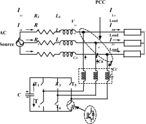
A Voltage Source Converter (VSC) based DSTATCOM is shown in Figure1. It is connected to a three phase transmission line feeding three phase non-linear load.
PCC
I
SA RS LS
I
LA
V
SA
Load I
SB
R
S LS
I LB
AC VSB
Load
Source ISC
R
S
L
S V
SC
I LC
Load
I
CA
I
CB
I
CC
LF
T1 T3 T5
C
T
4 T6 T2
Figure 1. DSTATCOM with Distribution system for Nonlinear loads
To overcome ripple in compensating currents, an interfacing inductors (Lf) are used at an ac side of VSC.
Passive ripple filters which are series combination of resistor and capacitor are used for filtering high frequency switching noise of VSC [8,9]. They are also connected at PCC. Nowadays, the same value of series connected capacitor and resistor as ripple filter is used in all three phase. The DSTATCOM currents (ICabc) are injected as
needed compensating currents to eliminate harmonics of load current and to compensate reactive power demand [10,11]. Hence loading due to reactive power components/harmonics is so much attenuated on the distribution system. The rating of the Insulated Gate Bipolar Transistor (IGBT) of the VSC depends on the voltage and current rating for the required compensation [12]. Generally, the rating of VSC for compensation is found to be 15% more than the reactive power from rated value [13,14]. The designed value of different auxiliary components of DSTATCOM such as interfacing inductor (Li), DC-bus voltage (Vdc) and value of DC-bus
capacitor (Cdc) are also given in Appendix.
B. Control Algorithm:
There are many control techniques available for generation of reference compensating currents for the control of VSC of three-phase three-wire DSTATCOM system. The PQ theory and the synchronous reference frame theory are used in this investigation for control algorithm. A block diagram of the control scheme is shown in Figure2.
The load currents, PCC voltages and DC-bus voltage of DSTATCOM are sensed and used as feedback signals.The PQ theory is based on a definition of instantaneous real and reactive power in time-domain. It is effective not only in the steady state but also in transient state analysis for three phase system.
Clarke transformation is used for extraction of dq-components of voltage and current.
In three-phase three-wire system, there are no zero sequence components. So we can neglect them. Instantaneous power calculation is done using dq-components.
P ( Vd* I d) ( Vq* Iq) Q ( Vd* I q) ( Vq* Id)
These powers contain average as well as oscillating components. The average values of both P and Q agree with conventional real and reactive power in ac system. The oscillating terms that naturally produce a zero mean give additional oscillating power flow without contribution of energy transfer neither from the source to the load nor from the load to the source. Hence to achieve the compensation, the oscillating component of P is eliminated using Butter-worth low pass filter. In order to compensate oscillating power flow by means of converters, the DC voltage across the DC bus capacitor must be large enough and kept constant at that level for effective compensation. Therefore, DC bus voltage regulator must be added to the control loop.
The oscillating component of Posc is found by following equation.
P
_
osc = P_loss+ P_avg
P
By obtaining Posc and Q components, dq-components of reference compensating are calculated.
Using inverse Clarke transformation, reference compensating currents are calculated using following equation.
To obtain switching pattern, the reference compensating currents are compared with the actual compensating currents injected by DSTATCOM to reduce each phase current error. The generated gating signals control the IGBT switches to inject a current such that the sensed compensating currents exactly follow the reference compensating currents.
III. DESIGN OF SYSTEM
2.Selection of interfacing inductor
3.Selection of DC bus capacitor
For parameter design, balanced ac supply and linear operating mode of the VSC are the assumptions.
1. DC bus voltage (Vdc):
The minimum dc bus voltage of VSC should be greater than twice the peak of the phase voltage of the system.
V
dc
2 2
V
LL3
m
Where m = modulation index (here m = 1), VLL = ac line voltage of DSTATCOM
2. Interfacing Inductor (Li):
The selection of interfacing inductor (Li) of VSC depends on the current ripple (icr(p-p)), switching frequency
(Fs) and DC bus voltage (Vdc).
L
i
12
3
mV
a F
dcs
i
cr ( p p )
Where a = overloading factor
3.DC bus capacitor (Cdc):
The value of DC capacitor (Cdc) for VSC depends upon the instantaneous energy available to DSTATCOM
during transient.
1
C
dc[(
V
dc_ref)
2
(
V
dc1)
2]
3
V
(
aI
)
t
2
Where Vdc1 = minimum voltage level of DC bus, V = phase voltage, I = phase current
IV. SIMULATION RESLUTS AND ANALYSIS
Simulation model of a DSTATCOM is constructed for a three phase distribution system using MATLAB (SIMULINK) and SimPower system (SPS) toolboxes in discrete time. The performance of Adaptive filter based control algorithm in time domain for the three-phase DSTATCOM is simulated in ZVR mode of operation for non-liner load.
A. Performance of control algorithm:
Figure3 shows the various in-between signals of control algorithm which include direct axis voltage (Vd),
quadrature axis voltage (Vq), direct axis current (Id), quadrature axis current (Iq), average power (Pavg), reactive
power (Q), direct axis compensating current (Icd), quadrature axis compensating current (Icq) and DC link
Figure.3 Various internal signals for reference compensating currents computation using Adaptive filter based control algorithm
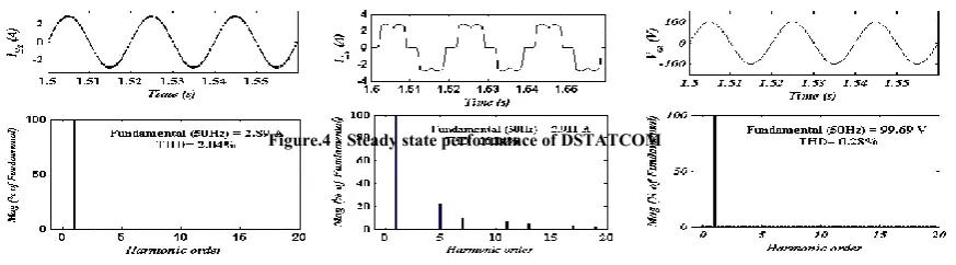
B. Performance of DSTATCOM in ZVR mode:
In ZVR mode, the amplitude of PCC voltage is regulated to the reference amplitude by injecting the required reactive power demand. Figure4 shows the steady state performance of DSTATCOM used for reactive power compensation required in voltage regulation and harmonic elimination under nonlinear loads. It includes signals of source voltage (Vs), source current (Is), load currents (ILa,ILb,ILc), compensating current (iCa,iCb,iCc),
reference compensating current (ICa*,ICb*,ICc*) and voltage across capacitor (Vdc). Under time average value of
PCC phase voltage (VSa), source current (ISa) and load current (ILa) are 99.69 V, 2.89A and 2.911 A
Figure.4 Steady state performance of DSTATCOM
The dynamic performance of DSTATCOM in terms of waveforms and harmonic spectra of phase ‘a’ is as
shown in Figure5. It is observed that, DSTATCOM will inject anti phase component of harmonic spectra available in supply current. So, that it will remove the harmonics from the supply current and make it sinusoidal as shown. It includes source voltage (Vs), source current (Isa,Isb,Isc), load current (ILa,ILb,ILc) and compensating
current (i Ca,iCb,iCc). Three phase PCC voltage are regulated to rated value (at t=1.3 to 1.4 sec). THDs of the
phase ‘a’ at PCC voltage, Source current and load current are 0.28%, 2.04% and 26.14% respectively as shown in Figure6.
Figure.5 Dynamic performance of DSTATCOM
(a) (b) (c)
Figure.6 Waveform and harmonic analysis of (a) Phase ‘a’ supply current (b) Phase ‘a’ load current
(c) Phase ‘a’ voltage at PCC in voltage regulation mode
It can be observed that the THD of the source current and PCC voltage are within IEEE 519-1992 standard limit of 5%. These result shows satisfactory performance of explained control algorithm used in DSTATCOM for reactive power compensation and harmonic elimination.
‘ TABLE I
PERFORMANCE OF DSTATCOM IN DISTRIBUTED SYSTEM
Performance parameters Nonlinear load(Rectifier with filter
(peak value) inductance)
PCC voltage (V),% THD 99.69 V (0.28%)
Supply current (A),% 2.89 A (2.04%)
THD
Compensator current (A) 4.5 A
Load current (A),%THD 2.911 A (26.14%)
DC bus voltage (V) 220 V
V. CONCLUSION
A DSTATCOM has been employed for compensation of unwanted components in distribution system, using adaptive filter based control algorithm on three-phase three-wire system. The adaptive filter based control algorithm has been used for extraction of real and reactive power compensation for generation of reference compensating current ZVR mode of DSTATCOM in non-linear distribution system. In all working condition, the THD of source current has been observed within an IEEE 519-1992 standard limit of 5%.The performance of DSTATCOM and its control has been found acceptable under varying load condition. Dynamic performance study of DSTATCOM for sudden change in load is also carried out, and the dc link controller provides proper regulation for the dc-capacitor voltages.
APPENDIX
DSTATCOM Parameters:
Supply: 3-phase, 122 V (L-L), 50Hz; Load: Non-linear: Three wire diode based rectifier with resistance R = 60ohm and inductance L = 20mH; capacitance value for DC link: 35µF; Reference voltage for DC link: 220V; Value of Interfacing inductor = 1.5mH; Sampling time = 5μsec; Low pass filter Fcutoff used for managing
voltage at DC link: 2nd order,10 Hz; Values of proportional gain (Kp) and integral gain (Ki) for managing
voltage at DC link: Kp 0.20 and Ki 1.50
REFERENCES
[1] H. Li and Z. Chen,” Overview of different wind generator systems and their comparisons,”IETin
Renewable Power Generation,vol.2,no.2, pp.123-138, June 2008.
[2] S. R. Arya, B. Singh, A. Chandra and K. AI-Haddad, “Control of DSTATCOM using adjustable step least mean square control algorithm,”in Proc. IEEE Fifth Power India Conference, 2012, pp.1-6.
[3] [3] U. K. Kalla, B. Singh and S. S. Murthy, “Adaptive noise suppression filter based integrated voltage and frequency controller for two-winding single-phase self-excited induction generator,” IET Renewable Power Generation, vol. 8, no. 8, pp. 827-837, 2014.
[4] B. Singh, S.K. Dube, S.R. Arya A. Chandra and K. Al-Haddad, “A comparative study of adaptive control algorithms in distribution static compensator,” in Proc. 39th Annual Conference of the IEEE In Industrial Electronics Society, 2013, pp.145-150.
[5] M. Labeeb and B.S. Lathika, “Design and analysis of DSTATCOM using SRFT and ANN-fuzzy based control for power quality improvement,” in Proc. IEEE Recent Advances in Intelligent Computational Systems, 2011, pp.274-279.
[6] A.V. Pavan Kumar, A.M. Parimi and K.U. Rao, “Investigation of small PMSG based wind turbine for variable wind speed,”in Proc.
International Conference on Recent Developments in Control, Automation and Power Engineering (RDCAPE),2015, pp.107-112.
[7] Bimal K. Bose, Modern Power Electronics and AC Drives, Person Education Inc, New Delhi, 2005. [8] A. Dahbi, M. Hamouda. N. Nait-Said and F.Z. Arama, “Analysis of different converters used in wind energy conversion system,”in Proc. International Conference on Renewable and Sustainable Energy, 2014, pp.352-359, 17-19 Oct. 2014.
[9] M.G. Molina and P.E. Mercado, “Control design and simulation of DSTATCOM with energy storage for power quality improvements,” in Proc. IEEE/PES Transmission and Distribution Conference and Exposition,2006, pp.1-7.
[10]M. Farhoodnea, A. Mohamed and H. Shareef, “A comparative study on the performance of custom power devices for power quality improvement,” in Proc.IEEE Innovative Smart Grid Technologies,2014,
pp.153-157.
[11]N.S. Patil and Y.N. Bhosle, “A review on wind turbine generator topologies,”in Proc. International
Conference onPower, Energy andControl (ICPEC), 2013, pp.625-629.
[12]L. Barote and C. Marinescu, “PMSG wind turbine system for residential applications,” in Proc. International SymposiumonPowerElectronics Electrical Drives Automation and Motion, 2010, pp.772-777. [13]Li Longji, Hua Geng; Geng Yang, Chuan Zhang, Chengyang Zheng and Chengyi Lai, “Comparisons of four rotor speed identification schemes for PMSG based WECS,” in Proc. InternationalConference onElectrical Machines and Systems (ICEMS), 2011, pp.1-6.
[14]A. A. Ahmed; K.M. Abdel-Latif; M.M. Eissa, S.M. Wasfy and O.P. Malik, “Study of characteristics of