IJIRT 142649
INTERNATIONAL JOURNAL OF INNOVATIVE RESEARCH IN TECHNOLOGY106
FUZZY CONTROLLED DSTATCOM FOR
HARMONIC COMPENSATION
Aswathy Anna Aprem
1, Fossy Mary Chacko
21
Student, Saintgits College, Kottayam
2
Faculty, Saintgits College, Kottayam
Abstract — In this paper, a suitable controller for Distribution Static Compensator (DSTATCOM) is designed for improving the power quality. Power Quality has become a major issue in the present power system network. The network complexity is increasing more rapidly and most of the loads are inductive in nature which draws more reactive power. This causes harmonics and voltage variations in power system. To maintain the proper operation of inter-connected power system, we are using one of the FACTS devices such as DSTATCOM. It provides suitable compensation and thereby maintains the desired power factor, voltage and also reduce the harmonic content in distribution network. The fuzzy logic controlled block diagram for DSTATCOM which is optimized using GA is incorporated and also it has been simulated. A comparative study of PI controlled and Fuzzy Logic Controlled DSTATCOM is also made. The simulation is taken out by MATLAB/SIMULINK and the result shows the effectiveness of GA optimized Fuzzy controlled DSTATCOM for improvement of power quality.
Index Terms --- Distribution Static Compensator (DSTATCOM), Fuzzy Logic Controller(FLC), Proportional and Integral Controller (PI controller), Genetic algorithm (GA).
I. INTRODUCTION
Due to insufficient reactive power support, the distribution power systems possess poor power
quality and dynamic performance during
disturbances. This can be due to harmonic pollution and load imbalance which causes extra stress on the networks and excessive voltage imbalance causing stress on other loads connected to the same network. Flexible AC Transmission Systems (FACTS) devices
such as Static Synchronous Compensator
(STATCOM)can be used to solve the power quality
issues related to transmission lines while
DSTATCOM can improve the power quality and
dynamic performance in a distribution network. The Static Synchronous Compensator (STATCOM) is a shunt-connected reactive power compensation device that is capable of generating and/or absorbing reactive power at a given bus location and in which the output can be varied [12].
The Distribution Static Compensator (DSTATCOM) can be controlled by various methods. Based on the control strategy its operation can be varied. Generally, Proportional and Integral (PI) controllers are used to control the operation of the DSTATCOM in the distribution power system [6]. However, the PI controlled DSTATCOM cannot provide optimal performance for different operating points since the power system is highly nonlinear and subject to various disturbances. More robust controllers such as the ones based on fuzzy logic approach [5] are required for the DSTATCOM to provide adequate dynamic voltage control, stability and to solve power quality issues like voltage flicker, Harmonics etc. of the distribution power system.
IJIRT 142649
INTERNATIONAL JOURNAL OF INNOVATIVE RESEARCH IN TECHNOLOGY107
In this paper, the design of GA (Genetic Algorithm) optimized Fuzzy Logic Controllers (FLCs) for a 3MVA DSTATCOM for improving the power quality and transient behaviour of a distribution network is presented. PI controlled and fuzzy logic controlled DSTATCOM for improving the power quality and dynamic performance of a distribution power system is simulated using SimPowerSystem in
MATLAB/Simulink environment and their
comparison is made. The dynamic performance, voltage flicker mitigation and harmonic conditions are evaluated.
II.SYSTEMCONFIGURATION
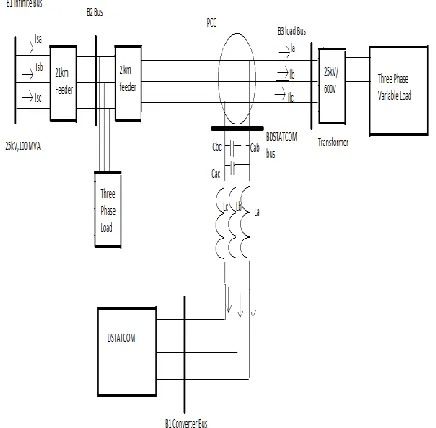
Fig. 1 shows a configuration of a network where DSTATCOM is used as a shunt compensator to regulate voltage on a 25-kV distribution power system. 21 km and 2 km feeders are used to transmit power to loads at buses B2 and B3, respectively. A variable load producing continuously changing currents and voltage flicker is connected to bus B3 through a 25kV/600V transformer. The DSTATCOM uses Voltage Source Converter (VSC) to regulate voltage at PCC by absorbing or generating reactive power using power electronics to regulate three phase sinusoidal voltage at its terminal. The VSC uses forced commutated power electronic devices (GTOs, IGBTs or IGCTs) to synthesize the voltage on the secondary side of the coupling transformer from a DC voltage source. A DSTATCOM with VSC using PWM inverters has been used in this study.
III.CONTROLSTRATEGY
In Fig. 2, PLL represents the phase-locked loop used to synchronize on the positive sequence component
of the three phase (3Φ) primary voltage V1. The
output of the PLL is θ =ωt and it is used to compute
the direct-axis and quadrature-axis components of the
AC (3Φ) voltages (Vd and Vq) and currents (Idand Iq).
The DC measurement system in Fig. 2 provides the
measurement of the DC voltage Vdc. The AC voltage
measurement and current measurement systems in
Fig. 2 measure the d and q components of AC
positive-sequence voltage and currents to be controlled, respectively.
Fig.1. System Configuration of a Distribution Network
.
IV.FUZZYLOGICCONTROLLERDESIGN
FORTHEDSTATCOM
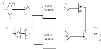
A fuzzy logic controller (FLC) consists of four elements. These are a fuzzification interface, a rule base, an inference mechanism, and a defuzzification interface. A FLC has to be designed for the DC voltage regulator, the AC voltage regulator, and the current regulator. The design of the FLC for DC voltage regulator, AC voltage regulator and current regulators follows similar procedures. In order to reduce the number of rules that is used in regular three-input PID-type FLC, two Sugeno-type FLC shown in Fig. 3 are used in this.
Fig.2. DSTATCOM control system block diagram.
IJIRT 142649
INTERNATIONAL JOURNAL OF INNOVATIVE RESEARCH IN TECHNOLOGY108
the input error scaling factor, GCE is the input rate of change of error scaling factor, GCU is the PI-type FLC output scaling factor, and GU is the PD-type FLC output scaling factor respectively.
Fig.3. Block Diagram of Fuzzy Logic Controller based DC voltage
Regulator
.
V.FUZZYLOGICCONTROLOPTIMIZATION
USINGGA
Many real world problems involve multiple measures of performance, or objectives, which should be optimized simultaneously. In certain cases, objective functions may be optimized separately from each other and insight gained concerning the best that can be achieved in each performance dimension. However, suitable solutions to the overall problem can seldom be found in this way.
The Genetic Algorithm (GA) is a global search technique based on the principles of genetics and natural selection. Search parameters are represented as genes and these parameters evolve under specified rules in order to find the optimum solution .The basic structure of the GA consists of coding, selection, mating (crossover) and mutation.GA is easy to implement and it is a robust and reliable method.
Designing a fuzzy PID controller involves
configuring the fuzzy inference system and setting the four scaling factors: GE, GCE, GCU and GU. We determine scaling factors GE, GCE, GCU and GU
from the Kp, Ki, Kd gains used by the conventional
PID controller. By comparing the expressions of the traditional PID and the linear fuzzy PID, the variables are related as:
Kp = GCU * GCE + GU * GE
Ki = GCU * GE
Kd = GU * GCE
A. Optimization of Scaling Factors Using GA
By using the optimization tool in the MATLAB, the tuning of the parameters can be done effectively. The
DC voltage regulator, AC voltage regulator and Current regulator has been tuned. The main objective is to minimize the fitness function.
The tabular representation of the FLC rule base (with 49 rules) for the DC voltage regulator is shown in table below.
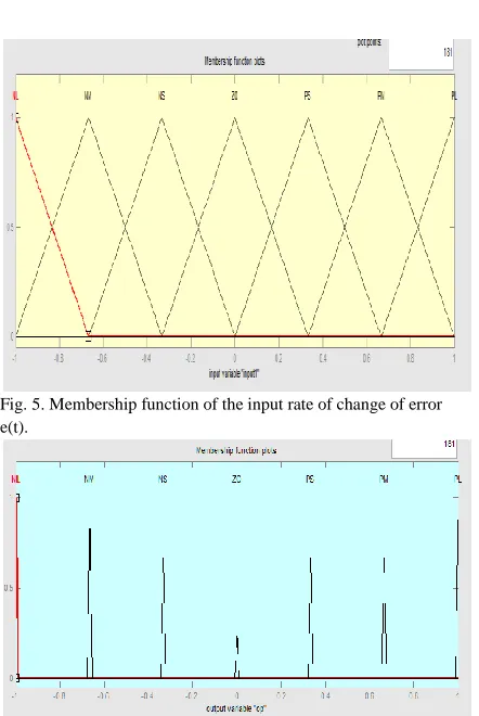
The size of inputs and output membership functions is chosen to be seven. The membership functions of the input variables for both the PI-type FLC and the PD-type FLC to be employed are of the triangular type and they are defined as shown in Figs. 4 and 5. The membership function of the output variable for both the PI-type FLC and the PD-type FLC are singletons as depicted in Fig. 6.
IJIRT 142649
INTERNATIONAL JOURNAL OF INNOVATIVE RESEARCH IN TECHNOLOGY109
Fig. 5. Membership function of the input rate of change of error e(t).
Fig. 6. Membership function of the output of the FLC.
VI. MATLABBASEDMODELLINGOFTHE
SYSTEM
Comparative study of PI controlled and fuzzy logic controlled DSTATCOM for improving the power quality and dynamic performance of a distribution power system is simulated using SimPowerSystem in MATLAB/Simulink environment.
In this paper, two control strategies of DSTATCOM are developed and compared:
1. PI controller
2. Fuzzy Logic Controller.
For analysis, different cases of the system are investigated.
1. Dynamic Response of both the PI controlled
and Fuzzy controlled DSTATCOM.
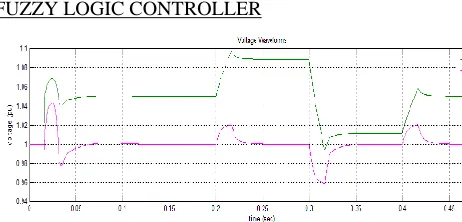
The dynamic response of a distributed power system subject to step changes in source voltage at the infinite bus is observed with the fuzzy controlled DSTATCOM and conventional PI controlled DSTATCOM. Fig. 7 shows the voltage at B3 when the source voltage has been changed by successively increasing the source voltage by 6%, decreasing it by
6% and bringing it back to its initial value at 0.2s, 0.3s, and 0.4s.
2. Mitigation of voltage flicker.
The mitigation of voltage flicker with the fuzzy logic
controlled and conventional PI controlled
DSTATCOM can be observed when the load is varied.
3. Harmonic Analysis.
By providing a non-linear load and imposing harmonics into the system, the operation of DSTATCOM to reduce harmonics can be observed and compared.
VII.SIMULATIONRESULTS
The simulation result for the MATLAB models is investigated. Based on the results obtained, the comparison of both the controllers is done.
A. Uncompensated System
Fig.7. Voltage at Buses 1 and 3 of distribution system without DSTATCOM
B. System with PI and Fuzzy controlled DSTATCOM
compensation.
1) Dynamic Response.
The dynamic response of a distributed power system subject to step changes in source voltage at the infinite bus is observed with the fuzzy controlled DSTATCOM and conventional PI controlled DSTATCOM.
PI CONTROLLER
IJIRT 142649
INTERNATIONAL JOURNAL OF INNOVATIVE RESEARCH IN TECHNOLOGY110
Fig. 8. Simulation output of Voltages at buses B1 and B3.
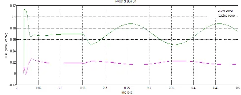
Fig. 9. Simulation output of Active and reactive power at bus B1.
Fig.10. Simulation output of DSTATCOM current.
FUZZY LOGIC CONTROLLER
Fig.11. Simulation output of Voltages at buses B1 and B3
Fig.12. Simulation output of Active and reactive power at bus B1.
Fig.13. Simulation output of DSTATCOM current. It can be deduced from the results that the dynamic response of the DSTATCOM can be improved much more by utilizing FLCs instead of conventional PI controllers. The advantage of using the FLCs with the proposed structure is that PI-type part of the FLC can be used separately without any additional adjustment required.
After a transient lasting approximately 0.15 sec., the steady state is reached. Initially, the source voltage is such that the D-STATCOM is inactive. It does not absorb nor provide reactive power to the network. At t = 0.2 s, the source voltage is increased by 6%. The D-STATCOM compensates for this voltage increase by absorbing reactive power from the network (Q=+2.7 MVAR). At t = 0.3 s, the source voltage is decreased by 6% from the value corresponding to Q = 0. The D-STATCOM must generate reactive power to maintain a 1pu voltage (Q changes from +2.7 MVAR to -2.8 MVAR).
2) Mitigation of voltage flicker.
The mitigation of voltage flicker with the fuzzy logic
controlled and conventional PI controlled
DSTATCOM can be observed when the load is varied.
IJIRT 142649
INTERNATIONAL JOURNAL OF INNOVATIVE RESEARCH IN TECHNOLOGY111
Fig. 14. Simulation output of Voltages at buses B1
and B3.
Fig. 15. Simulation output of Active and reactive power at bus B1.
Fig.16. Simulation output of DSTATCOM current. FUZZY LOGIC CONTROLLER
Fig. 17. Simulation output of Voltages at buses B1 and B3.
Fig. 18. Simulation output of Active and reactive power at bus B1.
Fig. 19. Simulation output of DSTATCOM current. Fig. 14 and 17 shows the voltage at B3 with the fuzzy controlled DSTATCOM and conventional PI controlled DSTATCOM. It has been observed that voltage at B3 varies between 0.96 pu and 1.04 pu (±4% variation) without DSTATCOM in Fig.8. It is observed in Fig. 14 that the voltage fluctuation at bus B3 is reduced to ±0.7% with the PI controlled DSTATCOM. The voltage fluctuation at bus B3 is further reduced in Fig. 17 to ±0.6% with both the PI-type and PID-PI-type fuzzy controlled DSTATCOM. The D-STATCOM compensates voltage by injecting a reactive current modulated at 5 Hz and varying between 0.6 pu capacitive when voltage is low and 0.6 pu inductive when voltage is high.
3) Harmonic Mitigation.
IJIRT 142649
INTERNATIONAL JOURNAL OF INNOVATIVE RESEARCH IN TECHNOLOGY112
LOAD CURRENT
WITHOUT COMPENSATION SOURCE CURRENT
WITH PI CONTROLLER
WITH FUZZY LOGIC CONTROLLER
From the above figures, we can observe that the THD has considerably reduced in the case of Fuzzy logic controller. The table below shows the comparison of THD levels obtained after simulation.
THD
Without DSTATCOM 25.85%
With PI controller 10.36%
With Fuzzy controller 1.14%
VIII. CONCLUSION
The design of FLCs for a DSTATCOM to improve power quality and dynamic performance of a distribution power system has done. FLC has to be designed for the DC voltage regulator, the AC voltage regulator, and the current regulator. The effect of Harmonic compensation using PI and Fuzzy Controller was evaluated. The results were compared with those of a conventional PI controlled DSTATCOM in the presence of source voltage variation and large load variations. The results show that the system’s performance was dramatically improved by using FLC compared to the PI controller. The simulation results obtained in
MATLAB/SimPowerSystems show that the
DSTATCOM controlled by the GA optimized FLC provides better system dynamic response and hence improves power quality and transient behaviour for the distribution power system.
REFERENCES
[1] A. Ghosh and G. Ledwich, “Load Compensating
DSTATCOM in Weak AC Systems,” IEEE
Trans. on Power Delivery, vol. 18, no.4, October 2003.
[2] G. F. Reed, M. Takeda, F. Ojima, A. P. Sidell, R.
IJIRT 142649
INTERNATIONAL JOURNAL OF INNOVATIVE RESEARCH IN TECHNOLOGY113
a 5MVA, 4.16kV D-STATCOM System for Voltage Flicker Compensation at Seattle Iron &
Metals,” IEEE PES SM, pp. 1605-1611, 2000.
[3] S. Kincic and A. Chandra, “Distribution Level
STATCOM (DSTATCOMs) for Load Voltage
Support,” IEEE Proceedings of Power
Engineering Conference on Large Engineering Systems, pp 30-37, 2003.
[4] Juan Shi, AkhtarKalam, Amin Noshadi, Peng
Shi “Genetic Algorithm Optimised Fuzzy Control of DSTATCOM for Improving Power
Quality” Australasian Universities Power
Engineering Conference, AUPEC 2014.
[5] D. Prasad, T. S. Kumar, B.V. Prasanth, and
K.S.G.Sankar, “Fuzzy Logic Control of D-Statcom for Power Quality Improvement”,
Int.Journal of Engineering Research and Applications, ISSN: 2248- 9622, Vol. 3, Issue 6, pp.398-403, November-December 2013.
[6] N. Sreekanth, N. Pavan Kumar Reddy, “PI &
Fuzzy Logic Based Controllers STATCOM For
Grid Connected Wind Generator”, Int.Journal of
Engineering Research and Applications, ISSN: 2248- 9622, Vol. 2, Issue 5, pp.617-623, September- October 2012.
[7] N.M.G. Kumar1, P. SangameswaraRaju and
P.Venkatesh, “Control Of DC Capacitor Voltage In A D-STATCOM Using Fuzzy Logic
Controller”, Int. Journal of Advances in
Engineering & Technology,,ISSN: 2231-1963,Vol. 4, Issue 1, pp. 679-690, July 2012.
[8] RehanAbidi, Dr.MutasimNour, “Analysis Of A
D-STATCOM In A 25 kV Power Distribution
System Using Simulink”, Int.Journal of
Electrical and Electronics Research, ISSN: 2348-6988, Vol. 2, Issue 2, pp.26-34, April - June 2014.
[9] Mohit Bajaj, Vinay Kumar Dwivedi, Ankit
Kumar, AnuragBansal, “Design And Simulation
Of DSTATCOM For Power Quality
Enhancement In Distribution Networks Under
Various Fault Condition”, Int.Journal of
Emerging Technology and Advanced
Engineering, ISSN:2250-2459, Vol. 3, Issue 4, April 2013.
[10] F. Herrera, M. Lozano, and J. L. Verdegay,
“Tuning Fuzzy Logic Controllers By Genetic
Algorithms”, Int.Journal ofApproximate
Reasoning.
[11] Y.T.R.Palleswari, B.Kali Prasanna And
G.Lakshmi, “Multi Level Statcom For Harmonic
Reduction”, International Journal Of
Application Or Innovation In Engineering & Management (Ijaiem), Issn 2319 - 4847volume 2, Issue 10, October 2013
[12] N.G.Hingorani and L.Gyuyi, understanding