Design and Analysis of LTE Wireless System
using Various Advanced Techniques
1
Parul Chopra,
2Dr. Deepak Kedia
1,2Dept. of ECE, Guru Jambheshwar University of Science & Technology, Hisar, Haryana India
Abstract
The LTE infrastructure is currently under development. In this paper Long Term Evolution (LTE) system is implemented by using advanced techniques like MIMO, scheduling algorithms etc. on both uplink and downlink to achieve high peak data rates and higher system throughput. This paper evaluates the LTE key performance indicators like throughput, end to end delay and jitter after employing advanced techniques. The LTE simulation has been carried out using the licensed network simulator QUALNET Developer 6.1.
Keywords
LTE, Performance Evaluation, Scheduling, Mobility, QUALNET 6.1
I. Introduction
With recent growth in the use of mobile technology applications, the extraordinary demand in the use of voice and data services has created an increase for other solutions to mobile broadband services. There has been substantial increase in the use of mobile devices for browsing the internet (web trending applications and websites, for examples, Facebook, and Twitter), video streaming (Russia Today, Al-Jazeera and Cable News Network (CNN) live broadcasts), Voice-over Internet Protocol (VoIP) applications for internet calls (Mobile VoIP and Skype), medical applications that run on real-time data loggings, video and voice calls and a number of new applications that has greater demands for high
data traffic [11].
The most significant factor involved in this technology is
that the service providers have been struggling to provide the demanded rates their customers want. Achieving a higher data
rate with significant wider but better coverage has posed a bigger
discussion in what could be the threat in meeting the subscriber’s demands.
The evolution towards the 4th generation of mobile communications (4G) has enabled the development and deployment of networks
implementing the Long Term Evolution (LTE) technology [1].
The Long Term Evolution (LTE) is the standard name given by the mobile technology project of the 3rd Generation Partnership Project (3GPP) to meet up with the set of requirements for present and future needs of mobile communications. The 3GPP LTE project started in 2004. The introduction of the LTE is aimed at enhancing the Universal Terrestrial Radio Access Network (UTRAN). Its evolvement is aimed towards achieving the fourth generation (4G) mobile technologies.
LTE technology is a founded on a 3GPP standard that offers a downlink speed of up to 150 megabits per second (Mbps) and an uplink speed of up to 50 Mbps. In LTE, Fixed wireless and wired standards are already approaching or achieving 100 Mbps or faster, and LTE is a way for cellular communications to be work at that
high data rate [11].
In this paper, the evaluation of all performance parameters of LTE system is carried out using QUALNET Developer 6.1. The
simulation model of MIMO-LTE gives efficient results in terms
of throughput, end to end delay and jitter. All the performance parameters are varied with different simulation parameters like bandwidth, application bit rate, speed etc.
The remainder of the paper is organized as follows. Section II provides an overview of the LTE architecture and its theoretical performances, outlining the major improvements introduced by the Long Term Evolution of Universal Mobile Telecommunications System (UMTS). Section III describes various advanced techniques used in LTE system. Section IV consists of Simulation scenarios and corresponding results. Section V concludes the paper.
II. LTE Architecture
The LTE architecture is of two type’s i.e. Radio access type and non-radio access type with Enhanced UTRAN (E-UTRAN). The radio access basically is the evolution of the LTE Physical Layer, while the non-radio access grouped under the System Architecture Evolution (SAE), is the development of the network architecture
of the LTE [8].
The major components of the LTE System Architecture are: User Equipment (UE)
1.
Radio Access Network (RAN) 2.
Evolved Packet Core (EPC) 3.
The LTE network is composed of the Core Network (CN), also called the EPC while there is the Access Network also, which is referred to as E-UTRAN. The Evolved Packet System (EPS) is comprised of the LTE Radio Access Network and Evolved Packet Core (EPC ⇒ RAN + EPS).
The LTE SAE (System Architecture Evolution) consists of UE, eNB and EPC (evolved packet core). The Particular device shows the eNB is like as the base station and UE has another name is mobile station. The LTE is also called as E-UTRAN
(Enhanced-UTRAN) The figure 1 shows the system architecture
with corresponding interfaces of E-UTRAN and UE.
Various interfaces are designed between various components which include Uu between UE and eNB, X2 between two eNBs and S1 between EPC and eNB. The eNB has been worked as both RNC and eNB.
Fig. 1: LTE Architecture Overview [9]
LTE is completely IP based network [1]. In LTE, to achieve the high transmit rates and excellent spectral efficiency in the downlink
the architecture are incorporated particularly in the Multi-Carrier and Multi-Antenna (MC-MA) transmission techniques, Hybrid Automatic Repeat Request (HARQ) etc.
In the LTE E-UTRAN transmission schemes, the Orthogonal Frequency Division Multiple Access (OFDMA) is designed for Downlink (eNB to UE), while the Single Carrier-Frequency Division Multiple Access (SC-FDMA) for Uplink (UE to eNB).
III. Advanced Techniques
LTE network provides high data rate, high mobility and higher system throughput due to the various advanced techniques like MIMO, mobility effects and eNB scheduling algorithms etc.
A. Multiple Input Multiple Output (MIMO) Antenna Techniques
Multi-antenna techniques are employed in LTE systems to achieve
high data rates, spectral efficiency, system capacity (number of
users), and coverage. Multi-antenna systems can be realized by using multiple antennas at the transmitter and receivers with an appropriate channel coding/ decoding scheme. By increasing the number of transmit and receive antennas it is possible to linearly increase the throughput of the channel with every pair of antennas
added to the system [7]. MIMO operation is an important feature
of E-UTRAN PHY.
QUALNET currently supports:
Single antenna transmission (SIMO). 1.
Multiple antenna transmission (MIMO) 2.
Transmit diversity (SFBC).
•
Open loop spatial multiplexing (OLSM).
•
For the transmission scheme, uplink can only use SIMO because the maximum number of transmission antennas is 1. For downlink, various transmission schemes are available. The various transmission schemes depend on the transmission mode number shown in Table 1.
Table 1: Transmission Mode and Transmission Scheme Mode
Number Transmission Scheme 1 Single Antenna transmission 2 Transmit diversity(SFBC)
3
RI=2: open loop spatial multiplexing(without CDD)
RI=1: Transmit diversity(SFBC) (switched dynamically depending in RI)
B. For eNB Scheduling Algorithms
Scheduling is the process of dynamically allocating physical resources to User Equipment’s (UEs) based on scheduling algorithms implemented at the LTE base station. Various algorithms have been proposed by network designers as the implementation of scheduling algorithm is an open issue in LTE standard. The choice of scheduling algorithm critically impacts resource utilization and
the overall performance of LTE network [3].
Two type of scheduling algorithm has been explored i.e. Round Robin (RR) and Proportional Fair (PF) scheduling algorithms for
Constant Bit Rate (CBR) traffic scenario.
C. By Using Mobility on UE Node
In this paper, we use the Waypoint Mobility. The Random Waypoint
Mobility Model is a variation of Random Walk model. It includes pause times between changes in direction and/or speed. A UE stays in one location for a certain period of time.
In LTE, the Mobility Management Entity (MME) is responsible for the mobility management function. The MME is connected to a large number of evolved Node (cells) that are grouped into the Tracking Areas (TAs). The TAs is further grouped into TA Lists (TALs). When a User Equipment (UE) moves out of the current
TA, it reports its new location to the MME [8].
IV. Simulation and Results
In QUALNET, a specific network topology is referred to as a
scenario. A scenario allows the user to specify all the network components and conditions under which the network will operate. This includes: terrain details, channel propagation, fading, and shadowing, wired and wireless subnets, network devices such as switches, hubs and routers, the entire protocol stack of a variety of
standard or user-configured network components, and applications running on the network [6].
A. Simulation Parameters
For LTE network simulation, various key parameters are required like terrain details, number of channels used, bandwidth etc. Simulation parameters are shown in Table 2.
Table 2: Simulation Parameters
SIMULATOR QUALNET 6.1 Terrain Size 1500x1500 m2
Antenna Omni directional Application Rates Mbps
Radio Type LTE
Propagation Model Two Ray Ground Channel Frequency 2.4GHZ
Traffic Source CBR application
Performance parameters Average Jitter, Average Delay, Throughput
B. Simulation Scenario
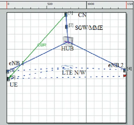
Figure 2 shows that the simulation scenario of LTE network which has 5 nodes, 1 hub and 1 wireless LTE centered network.
C. Scenario Description
In this section, detailed overview of LTE scenario is being provided. Various step followed for creating the simulation scenario of LTE system are describe below:
Place five nodes of the default device type on the canvas. •
Node 1 is the CN, node 2 is the SGW/ MME, node 3 is eNB 1, node 4 is eNB 2, and node 5 is the UE.
Create a point-to-point link between Nodes 1 and 2.
•
Place a wired subnet and connect nodes 2, 3, and 4 to it.
•
Place a wireless subnet and connect nodes 3, 4, and 5 to it.
•
Place a waypoint for node 5 close to node 3.
•
Default BER table files are included. •
Select the wireless subnet and set the LTE properties as
•
follows:
Go to Wireless Subnet Properties > Physical Layer and set
•
Radio Type to LTE PHY. Use default values for all PHY parameters.
Go to Wireless Subnet Properties > MAC Layer and set
•
MAC Protocol to LTE MAC. Use default values for all MAC parameters.
Go to Scenario Properties Editor > General > LTE
•
Configuration > Measurement > Mask of Events. Set Events
for RSRP Metric Handover Report to Observe A3 Events. Go to Scenario Properties Editor > Channel Properties. Set
•
Number of Channels to 4.
For node 3 (eNB 1), go to Default Device Properties > Interfaces
•
> Interface 1. (Make sure that Interface 1 corresponds to the wireless interface of node 3.)
Select the Physical Layer group.
•
Set Station Type to evolved Node B.
•
Set Listenable Channel Mask and Listening Channel Mask
•
to 1100.
Select the MAC Layer group and set Station Type to evolved
•
Node B.
For node 4 (eNB 2), go to Default Device Properties > Interfaces
•
> Interface 1. (Make sure that Interface 1 corresponds to the wireless interface of node 4.)
Select the Physical Layer group.
•
Set Station Type to evolved Node B.
•
Set DL Channel Index to 2 and UL Channel Index to 3.
•
Set Listenable Channel Mask and Listening Channel Mask
•
to 0011.
Select the MAC Layer group and set Station Type to evolved
•
Node B.
For node 5 (UE node), go to Default Device Properties >
•
Interfaces > Interface 0 > Physical Layer and set Listenable Channel Mask and Listening Channel Mask to 1111. Select the wired subnet and go to Wired Subnet Properties
•
> General
Set EPC Subnet to Yes.
•
Set EPC SGWMME Node ID to 2.
•
Set SGWMME Interface Index to 0.
•
Set up a CBR session between node 5 and node 1.
•
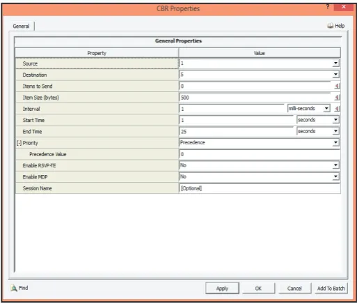
1. CBR Parameters
The CBR service category is used for connections that transport
traffic at a constant bit rate, where there is an inherent reliance on time synchronization between the traffic source and destination. In figure 3 shows CBR parameters in which item size, interval
and end time are shown. These values describe the application bit rate for LTE system.
In this paper, we use various application bit rates i.e. 2, 4, 8, 16 Mbps. In fig. 3, interval is 1ms and item size is 500 bytes. 4 Mbps application bit rate are shown in fig. 3.
Fig. 3: CBR Parameters Used in Simulation
D. Simulation Result
In this paper simulation has been done in two parts. Firstly simulation is done by consideration of MIMO techniques and then simulation is done using mobility effects.
By using the simulation model described the performance parameters has been evaluated in terms of throughput, end to end delay and jitter.
1. Simulation Results Using MIMO Technique
(i). Throughput
Network throughput is the average rate of successful message delivery over a communication channel. These data may be delivered over a physical or logical link, or pass through a certain network node. Throughput is usually measured in bits per second (bit/s or bps).
The throughput results obtained using MIMO are shown in fig. 4. In this figure, throughput results corresponding to SIMO, SFBC
and OLSM are present.
Fig. 4: Throughput Analysis of LTE Network Using MIMO
The performance of SIMO, SFBC and OLSM antenna techniques are analyzed for different application bit rate. It has been observed
SIMO and SFBC antenna scheme. Thus use of OLSM enables LTE support multimedia applications beyond web browsing and
voice, which demands higher bandwidth configurations.
(ii). End to End Delay
End-to-end delay indicates the length of time taken for a packet to travel from the CBR (Constant Bit Rate) source to the destination.
The End-to-end delay results obtained using MIMO are shown in
figure 5. In this figure shows End-to-end delay results corresponding
to SIMO, SFBC and OLSM are present.
Fig. 5: End To End Delay Analysis of LTE Network Using MIMO
It has been observed from the fig. 5 that the End To End Delay
over different application bit rate. In Fig. 5, end to end delay is lesser in the case of OLSM than SIMO and SFBC. Because of the multiplexing gain can easily be observed in the case of OLSM scheme.
(iii). Jitter
The variation in the latency of packets at the destination is termed as Jitter which is caused due to congestion, topology change etc. in a network. It occurs when in a transmission scenario different packets take different amount of time in reaching from source to destination. The jitter results obtained using MIMO are shown
in fig. 6.
Fig. 6: Jitter Analysis of LTE Network Using MIMO
2. Simulation Results Using Mobility Effects
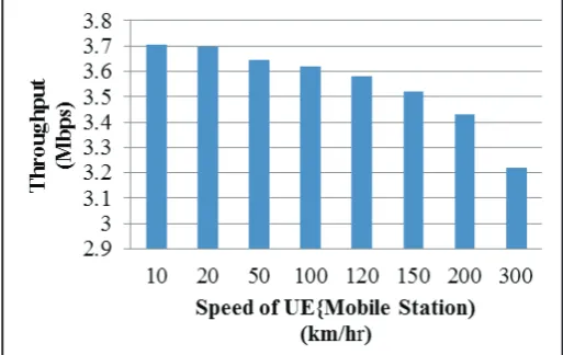
(i). Throughput
It is observed from the figure7 that throughput of LTE system
corresponding to mobility on UE (mobile station).
Fig. 7: Throughput Analysis of LTE Network Using Mobility
From fig. 7, we can say when the speed of mobile station is
increase then throughput decrease because interference increase with increase in speed, so number of packets loss increase then throughput decrease.
(ii). End-To-End Dealay and Jitter
The end to end delay results obtained using MIMO are shown
in fig. 8.
It is also observed that the delay and jitter performances of LTE system is also vary with speed. Higher mobility causes more links broken and frequent re-routing and thus causes larger end-to-end delay.
Fig. 8: End To End Delay Analysis of LTE Network Using
Mobility
As, speed of mobile station is increased, jitter and delay are also increased.
Fig. 8 and fig. 9 gives optimized speed is 100kmph because at this
speed end to end is minimum and jitter is also low.
V. Conclusion
In this paper, the performance of LTE network is analyzed by using advanced techniques such as MIMO and Scheduling algorithms in terms of throughput, end to end delay and jitter.
The simulation has been carried out by varying CBR application bit rate. Simulation results concluded that the performance of OLSM is better than SFBC and SIMO. In this paper, mobility effects are also considered in LTE. As we increase the speed of mobile station then throughput decrease and losses are increased. LTE supports the optimized performance for low speeds (< 15 km/ hr), high performance for speeds up to 100 km/hr and maintained performance for speeds up to 300 km/hr.
References
[1] A. Pastrav, D. Tataru, A. Bara, T. Palade, E. Puschita, “Key performance indicators evolution for LTE networks implementation,” 11th IEEE International Symposium on Electronics and Telecommunications, pp 1 – 4, Nov. 2014.
[2] V. K. Srivastava , G. Senthil Kumaran , A. Butare, “Goals of true broad band’s wireless next wave (4G-5G),” IEEE Vehicular Technology Conference, pp. 6-9, Oct. 2003. [3] Swetha1, Mohankumar and Devaraju, “Performance
Evaluation of Round Robin and Proportional Fair Scheduling
Algorithms for Constant Bit Rate Traffic in LTE,” IRACST
– International Journal of Computer Networks and Wireless Communications (IJCNWC), pp. 41-45, February 2013.
[4] Mohammad Torabi, Ali Jemmali and Jean Conan, “Analysis
of the Performance for SFBC-OFDM and FSTD-OFDM Schemes in LTE Systems over MIMO Fading Channels,” International Journal on Advances in Networks and Services,
vol7no1&2, pp.1-11, 2014.
[5] Ali Jemmali and Jean Conan, “Performance Evaluation
of MIMO Schemes in 5 MHz Bandwidth LTE System,”
The 8th International Conference on Wireless and Mobile Communications (ICWMC), pp.334-338, 2012.
[6] Temitope O. Takpor and Francis E. Idachaba, “Analysis
and Simulation of LTE Downlink and Uplink Transceiver,” Proceedings of the World Congress on Engineering, Vol. I, pp. 1-6, July 2 - 4, 2014.
[7] Mohana H K, Mohankumar N M, Swetha and Devaraju
J T, “The Study and Analysis of Effect of MultiAntenna Techniques on LTE network with Different Bandwidth
Configurations in the Downlink” Int. J. Advanced Networking and Applications, Vol. 6, Issue 3, pp. 2314-2318, November
30, 2014
[8] [Online] Available: http://liny.csie.nctu.edu.tw/document/
tmc11.pdf
[9] Mohana H K, Mohankumar N M, Suhas K R, Devaraju J
T, “Performance Evaluation of Mobility Effects on Various Transmission Modes in the LTE Network” International
Journal of Scientific & Engineering Research, Volume 6, pp. 618-622, June-2015
[10] A.E.I Pastrav, T.Palade and E.Puschita, “VoLTE Performances
in a 3D Modeled Campus Area,” IEEE International Conference on communication at Bucharest, pp. 1-4, May 2014. .
[11] [Online] Available: http://www.tutorialspoint.com/lte/lte_ network_architecture.htm.
[12] [Online] Available: https://aaltodoc.aalto.fi/bitstream/
handle/123456789/120 3/master_Oguntoyinbo_
Oludayo_2013.pdf?sequence=1
![Fig. 1: LTE Architecture Overview [9]](https://thumb-us.123doks.com/thumbv2/123dok_us/1337111.1642257/1.595.303.561.598.730/fig-lte-architecture-overview.webp)