Experimental Based Study on Behavior of RC (Cast-in-situ)
Beam-Column Junction and Precast Beam-Column Junction
Y.K.Rathod
1, N.L.Shelke
21
Post Graduate Student, Civil Engineering Department,
2
Professor, Civil Engineering Department,
Dr. D. Y. Patil School of Engineering and Technology, Charholi (Bk), Pune, 412105, Maharashtra, India
.
Abstract- In this study, we have design a junction of Beam-Column RC and Precast and then applying a different types of load on the junction specimen. Comparison between the load-deflection on both cases, Comparison between the exterior and interior joint with transverse reinforcement details as per IS 13920-1993 and SP16.Comparison between the previous lists of experimental work. The effect of axial load on the behaviour of joint is also considered in this study. That type of experimental work on precast beam-column junction has been never done at the plant of “Precast India Infrastructure Limited”. Comparison between the manually work which is done by the code of IS 13920-1993,IS 1893 part 1 – 2002 ,SP 16 and others. Comparison between the chemicals of precast members which is applied in the junction (Fosrok & Ultratech Power Grouting).
Index Terms– Precast Beam-Column junction, wooden kiln, static hydraulic machines etc.
I. INTRODUCTION
In RC frame buildings, portion of column that are common to beams at their intersection are called beam-column joint. In general, the performance of framed structures depends on the individual members such as beam and column when there is only gravity load acting on the structure. But when lateral load acting on the structure then performance of the structure depends not only with the individual member, also with the integrity of the joints. The beam-column joint plays a critical role in ensuring performance of RC frame structures in resisting the design force, particularly induced by earthquake force. In case of design, it is very important to design beam-column joint precisely because the individual member such as a beam or column in case of considerable damage can be strengthened by some methods, but a beam- column joint cannot be strengthened once it form the plastic hinge. Many researches are going around the worldwide to understand the behaviour of beam column joint in a better manner. Moreover, concrete is a
material possessing low thermal conductivity and high specific heat capacities.
II. OBJECT&SCOPEOFTHESTUDY
A beam-column joint is a very critical zone in reinforced concrete framed structure where the elements intersect in all three directions. Joints ensure continuity of a structure and transfer forces that are present at the ends of the members. We have to design the entire beam-column junction with different types of loading, design with different dimensions like depth of beam, height of column then due to applied load and varies the span of beam with all particular loading condition. Then after all the records of both precast and RC (cast-in-situ) beam-column junction should be designed and analysis as per different software’s.
1. Comparison between the performance of RC and Precast beam-column junction by using experimental work (static loading)
2. Comparison between the load-deflection on both cases 3. Comparison between the exterior and interior joint with
transverse reinforcement details as per IS 13920-1993 and SP16
4. Comparison between the previous lists of experimental work. The effect of axial load on the behavior of joint is also considered in this study
5. That type of experimental work on precast beam-column junction has been never done at the plant of “Precast India Infrastructure Limited”
III. METHODOLOGYOFWORK
Fig.1 Type1 Precast Beam-Column Junction with dimensions
Fig.2 RC Beam-Column Junction with dimensions
Fig.3 Type2 Precast Beam-Column Junction with dimensions
IV. TECHNICALWRITING
A. Analysis of cast-in-situ and precast beam-column junction an exterior type 1 junction
Given data
1. Column 800X800mm with a maximum load on the column 6336KN, bar diameter 4-32ϕ and 20-25ϕ 2. Main beam 800X700mm ultimate capacity 237.51
KN/m and tension steel 7 nos. 25mm (3436mm2) 3. Spandrel beam 450X450mm
4. IS 13920 (1993): Ductile detailing of reinforced concrete structures subjected to seismic forces 5. SP 16 (1980): Design Aids for Reinforced Concrete to
IS 456:1978
Assume grade of concrete M30 and Fe500, storey height 4620mm, if the joint may experience slow reversal of moment due to wind loads, design the junction :-
Load acting on the members of beam-column junction Live load – 5 KN/m2 as per IS 875 part 1,2,3,4 &5 Dead load or superimposed load as per the size of section Finish load – 1.25 KN/m2 as per IS 875 part 1,2,3,4 &5 Internal External walls are light weight wall of density 1KN/m2 Escalator load – 6KN/m2 as per IS 875 part 1,2,3,4 &5.
Total working load on the column by using manually and software
Step 1
Check column moment capacity from interaction dia. Column 800X800 mm,
Assume % of steel = 2 p/fckbD = 0.33 Mu/fckbD2 = 0.067 Mu = 1030X106 Nmm
But, column above and below the junction have twice this capacity i.e.
2X1030 = 2060 KNm.
Step 2
Check the stability condition of the column with the capacity of beam
ƩM col / ƩM beam = 8.6
Desirable capacity for class 1 junction = Fy/ 0.87Fy = 1.15 similar to 1.2.
Step 3
Check anchorage of 25mm bars (beam to column) Ldh = 0.27fyϕ / √fck = 616.18mm
Length available = 700 – cover – (diameter of the column bar) = 603mm
Anchorage can be made within the core and will give enough development length.
Minimum radius of bend r = 0.456fy/fck(1 + 2ϕ/a) ϕ Let a = 100mm, ϕ = 25mm, then
r = 285mm.
Step 4
Provide for confinement by minimum transverse steel
Spandrel beam is only on both side: confinement by transverse steel is needed.
S (spacing of tie) =100mm
H (large dimension of core = 370mm
Ash = 0.18SH (Ag/Ak – 1 )fck/fy = 67.42 mm2
Provide 10mm (78.54 mm2) at 100mm spacing with cross ties in both direction.
Step 5
Check for shear in column (type 1 joint)
Design shear in column = 1.2Moment of beam / storey height = 61.690 KN
υ = 0.096N/ mm2
(for type 2 joint, we will use a factor 1.4 )
Assume half as tension steel (2/2) = 1% as per IS 456 Table 19
Allowed τc = 0.66 N/ mm2 Hence Column safe in shear
V. EXPERIMENTALWORK
The prototype of the exterior beam-column joint was scaled down to its one-fourth size. The dimensions and reinforcement
details of the test assemblages are shown in Figures and in Table 1. The specimens in were detailed as per IS 13920 (BIS, 1993). All the two specimens were tested under constant axial load with cyclic load at the end of the beam. One of the specimens is RC beam column junction and another one is precast beam column junction.
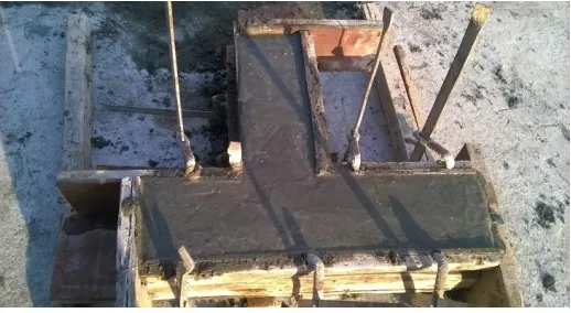
Fig.3 Casted Specimen of RC Beam-Column Junction with Grade of M30
VI. TESTSETUP
the end of the beam. One end of the column was given an external hinge support that was fastened to the strong reaction floor, and the other end was laterally restrained by a roller support. A schematic drawing of the setup is shown in Figure below. The experimental setup at the laboratory is shown in Figure below.
Fig.4 Specimen Setup
VII. CODESOFPRACTISE
Number of codes that are used for design and analysis of Transmission tower, for that study, refer following IS codes-
IS 13920 (1993): Ductile detailing of reinforced concrete structures subjected to seismic forces
IS 456:2000: Plain and Reinforced Concrete - Code of Practice [CED 2: Cement and Concrete]
IS 800 (2007): General Construction In Steel - Code of Practice [CED 7: Structural Engineering and structural sections]
IS 875 Parts-I -Code of Practice for Design Dead Loads,
IS 875 Parts-III -Code of Practice for Design Wind Loads.
IS 1893(part1): 2002 Criteria for Earthquake Resistant Design of Structures,
SP 16 (1980): Design Aids for Reinforced Concrete to IS 456:2000
VIII. RESULTSANDDISCUSSION
A. Analytical and Experimental Verification
All junction are design as per IS 13920 (1993): Ductile detailing of reinforced concrete structures subjected to seismic forces, IS 456-2000 and IS 800-2007
Taking seismic moment – (E) - 120 KN-m Seismic design shear – (VE) – 80 KN Grade M30 & Fe 500
TABLEI
Particulars results in Beam intersect all junctions S.No. Size of beam in
(mm)
Length (m) Total factored load (kN/m)
1 450 × 450 20.6 18.37
2 450 × 450 7.4 32
3 650× 1950 9.5 40.5
4 800 × 700 10 31.87
5 450 × 450 10 33.37
6 450 × 1870 7.5 40.5
7 800 × 700 10 43.5
Factored B.M (KN-m)
Factored shear force (KN)
Depth required (mm)
Check for shear
(τu)
500.1 216 518.10 -
130.05 180.36 264.2 0.97
282.03 238.5 323.73 0.19
237.51 210 267.79 0.39
249.9 216 366.42 1.17
284.76 278.25 400 0.33
IX. CONCLUSIONS
Experimental investigations were carried out on two types of simple mechanical concrete beam-column connections subjected to reverse cyclic loading. The results were then compared with the performance of a reference monolithic beam-column connection. The types of precast concrete connections considered for the present study are (i) Dowel Bar and (ii) The bar of beam merge into the column. The parameters considered for the present study are load carrying capacity, energy dissipation and ductility. The summary of the observations are as follows
I. When we compare to the precast specimen 1 and specimen 2 so the results is Sample with Dowel bar is have a greater capacity compare to another one when we applied a load on the column and the end of the column.
II. One more thing should be occurred in the junction that maximum failure of chances when we applied a load on the junction is top and bottom of the column for both specimen.
III. On comparison of both the precast specimens, specimen RC performed much better than the specimen PC-DW. Also, it is observed that the precast specimen, PC-DWCL exhibited satisfactory behaviour in comparison with the monolithic specimen ML.
IV. The proposed connection PC-DWCL is a simple dry connection that can be used for the construction of low rise moment resisting frames.
V. Considering the energy dissipation, the specimen RC performed better than the specimen PC-DW and dissipated 10.71% higher energy than specimen PC-DW. The energy dissipation of specimen PC-DWCL is about 16.52% lesser than the monolithic specimen ML.
VI. The specimen RC has better ductility than that of specimen PC-DW and monolithic specimen ML. About 38.04% and 16.56% increase in ductility had been observed for PC-DWCL compared to specimen PC-DW and specimen ML respectively.
The load carrying capacity of the connection with Type 1 and Type 2 exhibited 40% and 25% greater load carrying capacity than the specimen with dowel bar PC-DW in the positive and negative direction respectively. This is due to the additional stiffness developed due to the presence of cleat angle. Compared to the monolithic specimen ML, the specimen RC exhibited lesser load carrying capacity. The variation is 29.32% and 25.79% in the positive and negative direction respectively.
Results/ remarks Safe/unsafe
- Unsafe
Vu< 0.25√fck Safe
Vu< 0.25√fck Safe
Vu< 0.25√fck Safe
Vu< 0.25√fck Safe
Vu< 0.25√fck Safe
Vu< 0.25√fck Safe
S.No. Size of column in mm
Joint type
BM KN-m
1 800 × 800 Exterior 1030
2 1200 × 800 Interior 2304
3 1200 × 450 Exterior 488.4
4 800 × 800 Exterior 1030
Stability condition ∑Mcol / ∑Mbeam
Shear in column N/mm
Shear capacity at junction KN (Vu)
Check shear capacity at junction KN (Vn)
7.3 0.11 3374 4278
4.2 0.29 1876 41407
2.0 0.24 1148 2678.5
M-R calculation of RC and Precast Junctions
S. No. Load (KN)
Deflection Longitudinal Length
M-R Calculation
Specimen 1 390 (C) 1.55 800mm 1.24 Specimen 1 80 (B) 7.55 500mm 3.775 Specimen 2 80 (C) 2.55 800mm 2.04 Specimen 2 50 (B) 4.50 500mm 2.25
Specimen 2 420(C) 1.75 800mm 1.4
Specimen 2 80(B) 7.05 500mm 3.525
TABLEII
Particulars results in RC and precast Beam-column junction’s
The cracks patterns observed at the time of testing within ±2mm in the junction of RC when applied a load on the top of the column and end of the beam (Jack 1 has 1000KN and Jack 500KN)
The cracks observed at the top of the column within ±2.5mm Fig.5 Cracks Investigation of RC Beam-Column Junction
ACKNOWLEDGEMENTS
I express my profound gratitude to our project guide Dr Nagesh L. Shelke for their inspiring guidance due to which our difficulties and questions were shaped into the development of this project and complete support, cooperation and valuable suggestions.
Would like to thank the Principal, Dr Ashok S. Kasnale and H.O.D, Dr Sanjay K. Kulkarni of Civil Department. I also thank my parents, friends who were the source of inspiration throughout the making of this work complete.
REFERENCES
[1] Bindhu K R, Jeya K P and Manicka Selvam V K 2008 Seismic resistance of exterior beam-column joints with non-conventional confinement reinforcement detailing. Struct. Eng. Mech. 30(6): 733–761.
[2] Burcu B.Canbolat and James K.Wight, 2008, “Experimental Investigation on Seismic Behaviour of Eccentric Reinforced concrete Beam-Column-Slab Connections”, ACI structural journal, Vol 105, No.2, Pg. 154-162.
[3] Kumar, Sharad, ―A Study of Reinforced Concrete Beam-Column Joints Under Uni-Axial Bending‖, M.Tech, Dissertation, Inst. Of Technology, Benara Hindu University, Varanasi, 1988.
Results /remarks
Safe or unsafe
[4] Naveen Hooda, Jyoti Narwal, Bhupinder Singh, VivekVerma, Praveen Singh (2013), Experimental Investigation on Structural Behaviour of Beam Column joint.
[5] P. Asha, R. Sundararajan, Seismic behaviour of exterior beam-column joints with square spiral confinement, Asian Journal of Civil Engineering (Building and Housing). 12(3) (2011) 279-291.
[6] Shamim Mohammad and Kumar. V (1999) “Behavior of reinforced concrete Beam column joints-A review “Journal of Structural Engineering Vol.26, No.3, Pp.207-214. [7] S.M.Kulkarni, Y. D. Patil, (2012),“ A State-of-Art Review
on Reinforced Concrete Beam-Column Joints", Journal of Information, Knowledge and Research in Civil Engineering ISSN: 0975 – 6744 ,Nov 11 TO Oct 12 ,Volume 2, Issue 1, Page 94.
[8] S.M.Kulkarni, Y. D. Patil, (2014),”Evaluation of Advanced Reinforcement Pattern in Exterior RC Beam-Column Joint”, International Journal of Scientific & Engineering Research, ISSN 2229-5518,Vol 5,Issue 3, pp 624-629.
[9] Ramesh.S [2008]“Experimental study on behaviour of
Exterior RC
beam-column joint subjected to cyclic loading” M.E. thesis report, Anna University, Chennai, July-2008.
[10] Yogendra Singh, (2003), “Challenges in retrofitting of RC buildings”, Workshop on retrofitting of structures, IIT Roorkee, pp 29-44.
[11] Indian Standards,”13920 (1993): Ductile detailing of reinforced concrete structures subjected to seismic forces [12] Indian Standards,” General construction in steel” IS
800:2007, Bureau of Indian Standards , New Delhi
[13] Indian Standards, “Criteria for Earthquake Resistant Design of Structures” IS 1893(Part 1): 2002
Authors Biography First Author
Mr. Yash K.Rathod
B.E. (Civil Engineering), M.E (Civil) (Structures),
Post Graduate Student, Civil Engineering Department, Dr.D.Y.Patil School of Engineering and Technology, Charholi (Bk), Pune, 412105, Maharashtra, India. Second Author
Dr. Nagesh L.Shelke