LEAKAGE
CURRENT
MEASUREMENT
AND
HEALTH
MONITORING OF SURGE ARRESTERS
Koli Pradnya Pramod (Student)
1 & Dr. Uttam L. Bombale (Associate Professor)2I.INTRODUCTION
In the last few years the new type of high voltage surge arresters of metal oxide type became more importance in high voltage installations. The reason is that, compared with the classic SiC surge arrester, it has very important advantages such as, for instance, significant reduction in size, quick response for steep discharge current and superior protective performance. Several ways of monitoring the state of a ZnO surge arrester in service have been presented in the past. Most of the methods are based on measuring the leakage current in the ground connection of the arrester [1,2] since it is well known that the resistive component of the continuous leakage current is a good indicator of the surge arrester condition. A considerable increase in the continuous resistive current may be caused either by moisture ingress due to sealing problems, or by premature ageing of the ZnO arresters, in contrast to a transient rise in the resistive leakage current caused by a temporary increase in arrester temperature. The construction of ZnO surge arresters consist of a very simple structure. They basically Consist of an insulating housing which is made of porcelain or polymeric material, and the inner active column, composed of the ZnO arresters. The ZnO arrester block elements are the main component of the ZnO surge arrester. They provide the desired non-linear characteristics and present a strong relation with the temperature (low current range). The non-linear resistivity is an inherent bulk property of the composite ceramic resistor, which consists of mainly ZnO with relatively small amount of several additives of other metal oxides such as Bi2 O3, CoO2, MnO3, and Sb2O3 [3] These additives essentially determine the electric properties of the block arresters element.
Zinc oxide surge arresters should behave as an insulator at normal line to earth voltage. They have very high impedance resulting in leakage current with peak value of only a few mille amperes. During over voltage events the metal oxide surge arrester limits the voltage to an almost constant value, even if the discharge current increases extremely. This capability has been found to remain unchanged during its full life, but the insulation performance at operation voltage may subject to change [4]. However, under extreme condition this might lead to an increase of the leakage current. This change called degradation of metal oxide surge arrester. The third harmonic of the resistive leakage current is responsible to the degradation of ZnO surge arrester.
II.LEAKAGECURRENTINARRESTERS
The performance of surge arresters depends on the insulating property of metal- oxide (ZnO) used in arresters. The deterioration of the insulating property increases leakage current in the arrester. This leakage current depends on applied voltage and temperature at the time of measurement. The nonlinear characteristics of ZnO blocks used in arresters, clamps the over voltage generated due to surges and lightning, to normal level and ultimately protects the equipment in the switchyard. In
1
Department of technology ,Electronics department, Shivaji university kolhapur, maharashtra,India.
2
Department of technology ,Electronics department, Shivaji university kolhapur, maharashtra,India.
International Journal of Latest Trends in Engineering and Technology
Vol.(8)Issue(4-1), pp.143-148
DOI: http://dx.doi.org/10.21172/1.841.25
e-ISSN:2278-621X
Abstract- This gadget gives visual or remote indication of fault on the electric power framework. called as Leakage current meter, the gadget is utilized as a part of electric power distribution which organizes as a methods for recognizing damage of arresters and transformer placed at substation. Surge arresters are installed on transmission and distribution line in substations between phase and earth in order to improve lightning performance and reduce failure rates. High energy stresses and housing deterioration are the main factors of degradation and damage of surge arresters. Thus, there is need for testing and monitoring the Arresters, in order to verify their good condition and their ability to effectively protect the distribution line. There are number of methods are available to measure the arresters leakage current like point wave method, compensation method, harmonic analysis method. In this project the harmonic analysis method is use. The first purpose of this project is to continuous monitoring of surge arrester. The second purpose is to real time monitoring of substation. This project calculates the resistive leakage current which will effect on the damage of arresters. Also calculate the RMS and the total leakage current from the arresters and store the results. Finally these proposed and developed systems were installed at high voltage substation for testing.
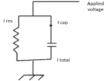
the normal application of arrester, at one end of the arrester, voltage is applied and the other end (base) is earthed. The leakage current in the arrester flows to the earth. The electrical equivalent circuit of the ZnO arresters is shown below [5]
Figure 1: Electrical equivalent circuit of ZnO surge arrester
The arrester, as shown in its electrical circuit, consists of parallel combination of resistor and capacitor. Thus the total leakage current is combination of resistive leakage current and capacitive leakage current. In normal life of an arrester, there is very little change in the capacitive current; whereas marginal change in resistive current is observed due to change in insulation property of arresters. The increase in resistive leakage current causes either by entering moisture in ZnO blocks or by premature ageing of the ZnO blocks. This resistive current is in phase with the applied voltage. So it generates power loss in the form of heat generation. Thus, the leakage current in arresters is divided between capacitive and resistive component. The capacitive current component is predominant and resistive component is significantly smaller. Typically under normal service conditions, the peak capacitive leakage current is in the range of 0.2mA to 3 mA. Generally, this value does not change due to change in characteristics of ZnO blocks.[6] At given voltage and temperature, the resistive leakage current component in arrester is very good indicator of changes in property of ZnO blocks. This component can be used as a diagnostic tool for condition monitoring of metal-oxide arresters. The resistive leakage current of a non-linear metal-oxide resistor is in the order of 5% to 20% of the capacitive current, corresponding to about 10 µA to 600 µA peak current. The resistive component under AC voltage is defined as the current level at the instant of voltage maximum (dv/dt = 0). The leakage current depends on applied voltage and temperature. The resistive current calculated is normalized to rating of arrester and 200 C temperatures. III. MEASUREMENTPRINCIPLE(THIRD HARMONICS)
Harmonics are created in the leakage current by the non-linear voltage current characteristics of the arresters. The harmonic content depends on the magnitude of the resistive current and on the degree of non-linearity of the voltage – current characteristics of metal oxide. This instrument reads the leakage current flowing through the Earthing conductor of arrester and calculates third order harmonics current from it. This current is shown as resistive current. A specially designed CT is used to read total leakage current flowing through the Earthing conductor of arrester. This CT should be placed in earthing conductor before the counter (i.e. between arrester base and counter). During the test, instrument takes several samples of current measured by CT. These samples are stored in memory. From the sampled CT current, the peak value is calculated and displayed as total current. [7] The frequency analysis is done using fast Fourier transformation on sampled CT current and amplitude of third harmonics is calculated. Similarly peak current and amplitude of third harmonics current in Field probe current is calculated. The percentage of third harmonics with respect to peak current, present in Field probe current is calculated. The third harmonic current calculated from CT current is compensated with this percentage. Thus the effect of harmonics present in system voltage is nullified and final result is displayed as resistive current.
The total current and resistive current calculated by instrument are peak current values. As the third harmonics is the largest harmonic component of the resistive current, it is most commonly used for diagnostic measurement. Please note, instrument calculates third harmonic current and shows as resistive current. For conversion from harmonics to resistive current, the third harmonic current needs to be multiplied by a constant factor. This depends on the information supplied by arrester manufacturer or from measurement in the laboratory. Instrument provides the facility of programming this factor. By default the factor is set to 1.
IV.CALCULATIONOFCORRECTEDRESISTIVECURRENT
The resistive current depends on system voltage (voltage applied to the arrester) and temperature at the time of measurement. To do the correct analysis of arrester, the value of resistive current at standard voltage and standard temperature has to be calculated.
Koli Pradnya Pramod
(Student) &Dr. Uttam L. Bombale
(Associate Professor) 145 The correction factor according to the ratio of system voltage and arrester rated voltage is calculated as follows. User is asked to enter phase to phase system voltage and arrester rating (rated voltage of arrester). Arrester rated voltage is phase to earth. [8]The ratio of voltage is calculated as follows.
Following formula is used to calculate IR corrected.
IRcorrected = I (TH) x (voltage multiplication factor) x (Temperature multiplication factor)
Vol. Ratio U/Ur Multipli cation Factor Vol. Ratio U/Ur Multipli cation Factor Vol. Ratio U/Ur Multipli cation Factor Vol. Ratio U/Ur Multipli cation Factor Vol. Ratio U/Ur Multipli cation Factor
0.4 3.4 0.5 2.5 0.6 1.7 0.7 1 0.8 0.5
0.41 3.3 0.51 2.4 0.61 1.6 0.71 0.9 0.81 0.5
0.42 3.2 0.52 2.3 0.62 1.5 0.72 0.8 0.82 0.5
0.43 3.1 0.53 2.2 0.63 1.4 0.73 0.8 0.83 0.4
0.44 3 0.54 2.1 0.64 1.4 0.74 0.7 0.84 0.4
0.45 2.9 0.55 2.1 0.65 1.3 0.75 0.7 0.85 0.4
0.46 2.8 0.56 2 0.66 1.2 0.76 0.7 0.86 0.4
0.47 2.7 0.57 1.9 0.67 1.1 0.77 0.6 0.87 0.3
0.48 2.7 0.58 1.8 0.68 1.1 0.78 0.6 0.88 0.3
0.49 2.6 0.59 1.7 0.69 1 0.79 0.6 0.89 0.3
0.9 0.3
Temp. T 0 C.
Multipli cationF actor
Temp. T 0 C.
Multipli cationF actor
Temp. T 0 C.
Multipli cationF actor
Temp. T 0 C.
Multipli cation Factor
Temp. T 0 C.
Multipli cationF actor
Temp. T 0 C.
Multipli cation Factor
-10 1.76 1 1.37 11 1.17 21 0.98 31 0.81 41 0.69
-9 1.72 2 1.35 12 1.15 22 0.96 32 0.79 42 0.68
-8 1.67 3 1.33 13 1.13 23 0.94 33 0.78 43 0.67
-7 1.63 4 1.33 14 1.12 24 0.92 34 0.77 44 0.66
-6 1.6 5 1.3 15 1.1 25 0.9 35 0.75 45 0.65
-5 1.57 6 1.28 16 1.08 26 0.88 36 0.74 46 0.65
-4 1.54 7 1.26 17 1.06 27 0.87 37 0.73 47 0.65
-3 1.51 8 1.24 18 1.04 28 0.85 38 0.71 48 0.65
-2 1.48 9 1.22 19 1.02 29 0.83 39 0.7 49 0.64
-1 1.42 10 1.2 20 1 30 0.82 40 0.69 50 0.64
0 1.4
Vol Ratio = System voltage (U) / LA rated voltage (Ur) Here System voltage U = System VPh-Ph / √3
Correction factor table for Rated Voltage
Correction factor table for Rated Temperature
Instrumentation Amplifier
Range selection Circuit & Buffer
Operational Amplifier with Gain
24 Bit ADC
Microcontroller
Controller Reset Circuit
Key board
Display
Buzzer
RTC
RF Module
USB interface I to V
converter
Battery DC-DC
5V/3A DC-DC
5V/200mA
Figure 2: block diagram of proposed system
VI.CIRCUITDIAGRAMOFPROPOSEDSYSTEM
Figure 3: circuit diagram analog section
Leakage current from the arresters can measure from the CT and the leakage current is given to the instruments as the input. The 510 ohm resister connected across the input current and it is converted in to the voltage. Further that the instrumentation amplifier is use. The CT having the ratio 1:2000 .the ladder circuit is used with the multiplexer. From 0 μAmp to 40 μAmp 5 groups are made and according to the fix the output 5V the multiplication stages and used. This is handling by the software. Further circuit is used for purification of the signal.
Koli Pradnya Pramod
(Student) &Dr. Uttam L. Bombale
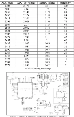
(Associate Professor) 147 The output of the analog section is read by the ADC and the digital output is given to the controller.ADC having +2.5 and -2.5 ref supply which is generated by using ADR 391 ref generator IC. Battery percentage is also calculated for the safety purpose. Instrument shows the battery percentage which is shown by the programming according with the following table.ADC count ADC i/p Voltage Battery voltage charging %
2703 2.178 12.1 100
2680 2.16 12 95
2658 2.142 11.9 89
2636 2.124 11.8 84
2613 2.106 11.7 79
2591 2.088 11.6 74
2569 2.07 11.5 68
2546 2.052 11.4 63
2524 2.034 11.3 58
2502 2.016 11.2 53
2479 1.998 11.1 47
2457 1.98 11 42
2435 1.962 10.9 37
2412 1.944 10.8 32
2390 1.926 10.7 26
2368 1.908 10.6 21
2345 1.89 10.5 16
2323 1.872 10.4 11
2301 1.854 10.3 5
2278 1.836 10.2 0
Table 2: battery percentage
Figure 5: circuit diagram of controller & display connection
The PIC32MZ2048EFH064 pic controller is used. It has the 2GB of storage memory. So we store approximately 1000 of results in the controller. 20 X 4 LCD display is used for the instrument. Having 4 rows and 20 columns. RTC section is also there by using the real term software we see the all result in the PC.
Third order harmonics in the leakage current
When voltage is applied to the arrester, due to non-linear voltage current characteristics of a metal-oxide used in arresters, harmonics in the leakage current is generated. This harmonic component depends on resistive component of arrester. The resistive component depends on applied voltage and temperature. Thus, due to this resistive component, major increase in third order harmonic component is observed. The magnitude of third order harmonics in the leakage current can be used as indicator of resistive current.
VII.SYSTEM HARMONICS
harmonics in leakage current of arrester may considerably be influenced due to these system voltage harmonics. To get correct results, we need to compensate the effect of these system harmonic contents.
Measurement of total leakage current
The total leakage current (I total) in arresters consists of capacitive and resistive current. As the resistive current is only a fraction of capacitive current, the total current mainly depends on capacitive current. The total leakage current is sensitive to the installation of arrester, as this depends on the stray capacitances. Large change in resistive current is needed to observe significant change in total leakage current.
On-line measurement of total leakage current is done using mA-meters built in surge arresters. These meters show R.M.S. values of total leakage current. As the resistive current is very small compared to total leakage current, change in resistive current is not noticeable using these meters. True analysis of diagnosis of arrester health is not possible by measurement of only total leakage current.
Measurement of resistive leakage current
The increase in resistive component of arrester increases resistive leakage current. This current is in phase with applied voltage. Increase in this current increases power loss in arrester. Monitoring and analyses of the resistive current gives true picture of power loss in arrester. Thus, the measurement of resistive leakage current in metal oxide arrester is good indicator of health of arresters. [9]
The resistive component under AC voltage is defined as the current level at the instant of voltage maximum. [10] Ic is generally – 0.2 – 3 mA for a typical arrestor.
Ir ranges from – 10 to 600 μAmp. – New: around 25 uAmp
– More than 5 years old: around 150 uAmp VIII.CONCLUSITION
From the above discussion it can concluded that the accuracy of the leakage current of the harmonics method of measurement is better from any of the method. This instrument gives accuracy up to +/- 5%.
It is show the third harmonic value i.e. the resistive leakage current .which is the main factor to degradation of the arrester. This instrument also calculates the Vrms value and the Vpeak value. The Vrms is varying voltage which is equivalent to steady DC value which gives the same effect at output. And Vpeak is voltage at maximum pic point is equals to the total leakage current. Ir value is varying from 10 to 600 μAmp. But above the 600 μAmp the arrester is considered as faulty. Continuous monitoring of surge arresters are possible from this system .It also stores the results up to 400 tests which is very important.
IX.REFERENCES
[1] H. Breder, T. Collin, "Supervision of Gapless Zinc-Oxide Surge Arresters", IEE Conference on Lightning and Power Systems, June 1984.
[2] S. Shirakawa,etal., "Maintenance of SurgeArrester by a Portable Arrester Leakage Current Detector", IEEE Transactions on Power Delivery,Vol. PWRD-3, No. 3, July 1988, pp. 998-1003.
[3] Eda, K. et al. (1989). Zinc Oxide Varistors, IEEE Electrical Insulation Magazine; Vol. 5; No. 6;Nov-Dec 1989, pp. 28-41
[4] Christian, H. et al,” Diagnostics and Monitor of Metal-Oxide Surge Arrester in High- Voltage Networks-Comparison of Existing and Newly Developed Procedures “, IEEE Trans. on Power Delivery Vol.16, No. 1, Jan.2001
[5] J.Lundquist, et al, “New Method For Measurement Of The Resistive Leakage Current Of Metal-Oxide Surge Arrester In Service”,1 IEEE Trans. On PowerDelivery, Vol.4, No.4, November 1990.
[6] H. Breder, T. Collin, "Supervision of Gapless Zinc-Oxide Surge Arresters", IEEE Conference on Lightning and Power Systems, June 1984.
[7] C.A. Spellman et al,” A Technique for On-Line Monitoring of ZnO Surge Arrester”, 10th International Symposium on High Voltage Engineering, Canada, August, 1997.
[8] S. Shirakawa, etal., "Maintenance of Surge Arrest By Portable Arrester Leakage Current Detector" ,IEEE Transactions on Power Delivery Vol. PWRD-3, No. 3,July 1988, pp 998-1003.
[9] HEINRICH C., HINRICHSEN V.: „Diagnostics and monitoring of metal-oxide surge arresters in high-voltage networks –comparison of existing and newly developed procedures‟, IEEE Trans. Power Deliv., 2001