531
Real-Time Implementation Of A New Efficient
Algorithm For Source Separation Using Matlab &
Arduino Due
Mohcin Mekhfioui, Rachid Elgouri, Amal Satif, Laamari Hlou
Abstract: The Blind signal separation consists of figuring out a hard and fast of indicators of the unknown source from a hard and fast of located signals. This work describes an efficient method to implement a general-purpose blind source separation algorithm on a low-cost microcontroller, without advanced knowledge of programming languages. The choice of the separation algorithm is based on the calculation of the Signal to Interference Report (SIR) inside the Arduino Due board. The basic signals are generated by two generators and sent to the Arduino board via the analog pins.
Index Terms: Blind Source Separation, BSS,ACI, Arduino Due, Matlab/Simulink, Real Time Workshop.
————————————————————
1.
INTRODUCTION
Blind Signal Separation (BSS) is a swiftly developing discipline in the signal processing community that gives an answer for isolating blended signals in the course of their propagation. The BSS, therefore, is composed in estimating a hard and fast of unknown source alerts from a fixed of located indicators which are mixtures of these source signals. With no additional hypothesis, the problem accomplished by the BSS is an incorrect problem posed. This is why all BSS strategies have assumptions about each source and mixing [1], [2]. Source separation strategies were carried out in numerous medical and technological fields, which include telecommunications, acoustics, imaging and biomedical sign processing. Previously, few studies are carried out on the real-time implementation of blind source separation. Yiu and Yong Low [3] proposed a real-time signal blindness noise reduction system exploiting the spatial diversity of source mixtures received by different sensors and kurtosis measurements. In 2019 Mekhfioui and all [4] implemented the SOBI algorithm on a DSP using MATLAB Simulink and TMS320C6713 DSK to validate its performance in real- time. This paper presents a new efficient algorithm to implement real-time blind source separation on the Arduino Due board without requiring detailed knowledge of programming languages. The concept is to use the Simulink Support Package Library for Arduino hardware, which integrates with the MATLAB-based graphical environment and does away with the need for programming. This work is structured as follows: Section II presents the principle of the blind source separation BSS and its mathematical model, the Arduino Due card, Section III presents the proposed workand the signals used. Section IV describes the Implementation and results, and finally, Section IV concludes this paper.
2
MATERIAL
A
NDM
ETHODOLOGY2.1 About Blind Source Separation
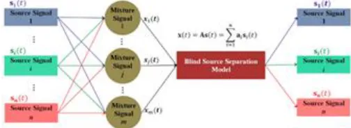
The Blind Source Separation (BSS) is based totally on estimating unknown source signals from their located combos when there is very little information to be had on the mixing model[5].
Fig. 1: Principle of the separation of sources
The basic model of the blind source separation (BSS) depends on the assumed mixing model, in the general case the equation of the instantaneous linear mixing is written as follows:
𝑥(𝑡) = ∑ 𝑎 𝑠(𝑡) + 𝑣(𝑡) (1) 𝑖 = 1, 2, … , 𝑚 and 𝑗 = 1, 2, … , 𝑛
Where
𝑥(𝑡) = [𝑥 (𝑡), . . . , 𝑥 (𝑡)] is the vector containing the observations;
𝑎 is the mixing system;
𝑠(𝑡) = [𝑠 (𝑡), … , 𝑠 (𝑡)] is the vector containing N signals emitted by N unknown sources;
v(t)is an additive noise vector we consider it negligible in the rest of the calculations.
The matrix form of equation (1) is written as follows:
𝑋(𝑡) = 𝐻𝑆(𝑡) (2) Where H is a mixture matrix of size 𝑛 × 𝑚
It is about finding in the ideal case the matrix W of size𝑛 × 𝑚which inverts the mixture and provides the output vector:
𝑦(𝑘) = 𝑊𝑥(𝑘) = 𝑊𝐻𝑠(𝑘) ≈ 𝑠(𝑘) (3) The estimated sources are given by the vector 𝑠(𝑘)and their corresponding projections for the different microphones are given by the estimated matrix: 𝐻 = 𝑊 .
2.2 Evaluation criteria
The performance of the algorithms of the Blind Source Separation BSS is evaluated via calculation of the Signal-to-————————————————
M.MEKHFIOUI, Laboratory of Electrical Engineering and Energy Systems, Ibn Tofail University, Kenitra, Morocco. Email: [email protected]
R.ELGOURI, Laboratory of Electrical Engineering and Telecommunications Systems, ENSA, Ibn Tofail University, Kenitra, Morocco. Email: [email protected]
A.SATIF, Laboratory of Electrical Engineering and Telecommunications Systems, ENSA, Ibn Tofail University, Kenitra, Morocco. Email: [email protected]
Interference Ratio (SIR). It is expressed in dB is defined for each source 𝑠by [4]:
SIR = max {10. log ( ∑
[ , ]
)} ∀j [1, N] (4)
Where the values g (i, j = 1, … , N)are the coefficients of the matrix of performances G equal to the product of the matrices of mixture A and of separation W, G = A ∗ W.
Knowing that each report SIR quantify the quality of source separations.
We define the SIR, which quantifies the performance quality of the BSS algorithm used to separate all sources by:
SIR = ∑ SIR (5) More SIR, the higher the separation is good and the BSS method used is efficient [4].
2.3 Arduino Due card
The Arduino Due is a programmable card based on a low-cost ARM Cortex-M3 microcontroller. It contains 54 digital pins (including 12 PWM), an 84 MHz clock, 4 UARTs, 12 analog inputs, a JTAG header Fig.2. [6]
Fig. 2: Schematic diagram of an Arduino Due card
The analog input ports of this Arduino have a resolution of 10 bits (values in the range 0 to 1023), implying that an input voltage of 0V is as value 0, and an input voltage of 3.3V is represented as a value 1023. On the other hand, the DAC analog outputs have a resolution of 8 bits, with the option of operating with a 10 bit resolution the value of 0 creates an output potential of 0.55v and the value 1023 is transformed into an output of 2.77v Table 1.
Table1: Technical specification of the Arduino Due
Microcontroller AT91SAM3X8E
Clock Speed 84 MHz
SRAM 96 KB
Flash Memory 512 KB
Digital I/O Pins 54 Analog Output Pins 2 Analog Input Pins 12 Operating Voltage 3.3V Input Voltage (limits) 6-16V Input Voltage (recommended) 7-12V DC Current for 5V Pin 800 mA DC Current for 3.3V Pin 800 mA DC Output Current 130 mA
3 PROPOSED
WORK
The objective of this work is to implement in the Arduino board an algorithm that groups together several source separation methods. Based on the calculation of the Signal to Interference Ratio (SIR) of each algorithm, the results of the
more efficient algorithm will be visualized on an oscilloscope. The index of the performing algorithm will also be displayed on the binary LEDs linked with the pins of the Arduino Due board. We have used the Matlab/Simulink blocks and functions for signal separation as a useful, efficient and easy to program tool. The separation method will be executed in a low-cost microcontroller to meet different applications in signal processing.
Signal separation in the Arduino board takes place in four main states:
Signal pre-processing blocks to prepare the signal for the next block ;
Signal mixing blocks for mixing the input signals; Signal processing using blind source separation
algorithms;
Signal post-processing blocks to display the output signal;
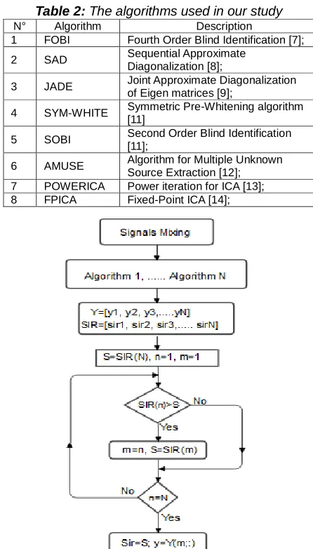
The signal processing unit allows the selection of the most efficient algorithm for the separation of input signals, based on the calculation of the signal-to-interference ratio (SIR) of various algorithms and separation methods Table 2. The diagram of this step is shown in Fig. 5.
Table 2: The algorithms used in our study
N° Algorithm Description
1 FOBI Fourth Order Blind Identification [7]; 2 SAD Sequential Approximate
Diagonalization [8];
3 JADE Joint Approximate Diagonalization of Eigen matrices [9];
4 SYM-WHITE Symmetric Pre-Whitening algorithm [11] 5 SOBI Second Order Blind Identification
[11];
6 AMUSE Algorithm for Multiple Unknown Source Extraction [12]; 7 POWERICA Power iteration for ICA [13]; 8 FPICA Fixed-Point ICA [14];
Fig. 3: Blind source separation flowchart
3.1 Signal model
533 two basic signals (s1 and s2) of the same shape and different
frequencies (800Hz and 400 Hz).
These signals were combined linearly by a mixing matrix A to produce the input signals 𝑥and𝑥 (in this article, we use the same mixing matrix to compare the different algorithms).
= (0.35 0. 6 0.63 0.42)
4 RESULTSANDDISCUSSION
4.1 Implementation and Experimental Results
In this part, our separation method has been implemented in an Arduino Due card. To test the implementation, two GBF generators have been used to generate the input signals x1 and x2, an oscilloscope to view the output signals, and LEDs to indicate the index of the most efficient algorithm Fig.4.
Fig. 4: Hardware setup for system separation
To use the Arduino block in Matlab, Simulink Support Package Library for Arduino hardware must be installed,it can be obtained and installed by clicking on the Add-On on Matlab.
When the installation is complete, the library can be added to the Simulink Library Browser as a Simulink support package for Arduino[15].
Simulink needs to be configured and operated with Arduino Due. In the simulation options, the external model is enabled to run in real-time with the external hardware. When execution is requested, RTW converts the Simulink block diagram into C/C++ code, in order to compile and download the code into the microcontroller. The code is run in real-time with the chosen sampling time in the blocks and the selected signals are sent to Simulink via USB interface. Figure 5 show the diagram of the Real-Time Workshop [16].
Fig. 5: Flow diagram of the procedures for implementingthe model on Arduino Due
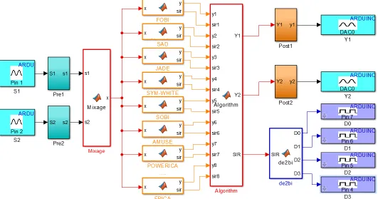
Fig. 6 shows a design of our real-time blind source separation approach using the Arduino Due Board based on Matlab / Simulink.
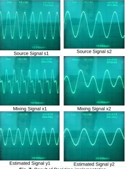
In a real application, if the number of outputs is more than two, we can use switches linked with the Arduino board to define the output to be displayed on the oscilloscope. With our workstation, we are able to separate the input signals in real-time using our algorithm designed on Matlab/Simulink and the Arduino Due board. To observe the different signals (source signals, mixed signals, and estimated signals), we have to change the binary value of the link switches with the Arduino (Fig. 7). In addition, we have used the link LEDs with the Arduino board to display the index of the most efficient algorithm to separate our signals fig. 8. The equivalence between the index and the algorithm is described in table 2 above.
Fig. 8: The index of the best performing algorithm
Source Signal s1 Source Signal s2
Mixing Signal x1 Mixing Signal x2
Estimated Signal y1 Estimated Signal y2 Fig. 7: Result of Real time implementation
The implementation results show a behavior similar to that of
the results obtained by simulation on the ICALAB [17], which confirms the performance of our method, with no need to use a computer or separation software.
5 CONCLUSION
In this work, we used the Matlab/Simulink blocks dedicated to real-time signal processing, to separate two mixed signals linearly by a grid A, using an efficient method based on the calculation of the Signal to Interference Ratio (SIR) of a group of algorithms inside the Arduino board. To validate this performance in practice and in real time, we implemented our method in the Arduino Due board, and thanks to two generators and an oscilloscope, and LEDs we obtained results similarly to those of Matlab.
REFERENCES
[1] C. Jutten and J. Herault, "Space or time adaptive signal processing by neural network models," AIP Conference Proceedings, pp. 206-211, 1986.
[2] C. Jutten and J. Herault, «Blind separation of sources, part I: An adaptive algorithm based on neuromimetic architecture,» Signal Processing, vol. 24, n° %11, pp. 1-10, 1991.
[3] K. Yiu et S. Y. Low, «On a Real-Time Blind Signal Separation Noise Reduction System,» International Journal of Reconfigurable Computing, vol. 2018, p. 9, 2018.
[4] M. Mekhfioui et al., « A Comparative Study and Implementation of Blind Source Separation Algorithm using MATLAB and TMS320c6713 DSK », J. Eng. Appl. Sci., vol. 15, no 5, p. 1074‑1081, dec. 2019, doi: 10.36478/jeasci.2020.1074.1081.
[5] H. Arahmane, E. Hamzaoui et R. Cherkaoui El Moursli, «Neutron Flux Monitoring Based on Blind Source Separation Algorithms in Moroccan TRIGA MARK II Reactor,» Science and Technology of Nuclear Installations, vol. 2017, 2017.
[6] «Arduino Due,» Arduino Inc, [En ligne]. Available: https://store.arduino.cc/due. [Accessed 05 02 2020]. [7] K. Nordhausen et J. Virta, «An overview of properties
and extensions of FOBI,» Knowledge-Based Systems, vol. 173, pp. 113-116, 2019.
[8] X. Li et X. Zhang, «Sequential Blind Extraction Adopting Second-Order Statistics,» IEEE Signal Processing Letters, vol. 14, n° %11, pp. 58-61, 2007. [9] J. F. Cardoso et A. Souloumiac, «Blind beamforming
for non-Gaussian signals,» IEEE Proceedings F - Radar and Signal Processing, vol. 140, n° %16, pp. 362-370, 1993.
[10] A. Cichocki, S. Osowski et K. Siwek, «Prewhitening Algorithms of Signals in the Presence of White Noise,» chez 6th International Workshop Computational Problems of Electrical Engineering, Zakopane, Poland, 2004.
[11] C. Wang, J. Wang et T. Zhang, «Operational modal analysis for slow linear time-varying structures based on moving window second order blind identification,» Signal Processing, Vols. %1 sur %2169-186, p. 133, 2017.
[12] L. Tang, R. Liu, V. C. Soon et Y. Huang, «Indeterminacy and identiability of blind identication,» IEEE Transactions on Circuits and Systems, vol. 38, n° %15, pp. 499-509, 1991.
535 on Diagonalizations of Non-Linearized Covariance
Matrix,» chez First International Conference on Innovative Computing, Information and Control, Beijing, 2006, pp. 730-733.
[14] A. Hyvärinen et E. Oja, «A Fast Fixed-Point Algorithm for Independent Component Analysis,» Neural Computation, vol. 9, n° %17, pp. 1483-1492, 1997. [15] «Arduino Support from MATLAB,» MathWorks, Inc,
[En ligne]. Available:
https://www.mathworks.com/hardware-support/arduino-matlab.html. [Accessed 05 02 2020]. [16] M. Mekhfioui, R. Elgouri, A. Satif and L. Hlou, «
Arduino Due Implementation of an Algorithm for Blind Source Separation using Matlab Simulink», International Journal of Innovative Technology and Exploring Engineerin, vol. 9, no 2, p. 3692-3696, dec. 2019, doi:10.35940/ijitee.B7385.129219.