(will be inserted by the editor)
HDMM: Deploying client and network-based
Distributed Mobility Management
A hybrid approach
Fabio Giust · Carlos J. Bernardos ·
Antonio de la Oliva
the date of receipt and acceptance should be inserted later
Abstract Mobile operators are now facing the challenges posed by a huge data demand from users, mainly due to the introduction of modern portable devices and the success of mobile applications. Moreover, users are now ca-pable to connect from different access networks and establish several active sessions simultaneously, while being mobile. This triggered the introduction of a new paradigm: the distributed mobility management (DMM) which aims at flattening the network and distributing the entities in charge of managing users’ mobility.
In this article, we review existing DMM proposals and describe a hybrid solution which benefits from combining a network-based and a client-based approaches. We analyze the signaling cost and the handover latency of our proposal, comparing them with their centralized alternatives. We also include validation and performance results from experiments conducted with a Linux-based prototype, which show that achievable enhancements depend on the underlying network topology. We argue that the proposed hybrid DMM solu-tion provides addisolu-tional flexibility to the mobile network operators, which can decide when and how to combine these two approaches.
Keywords Distributed Mobility Management · IP mobility · PMIPv6 · wireless systems · address reachability · cellular architecture · handover mechanisms·experimental evaluation
The research leading to these results has received funding from the European Commu-nity’s Seventh Framework Programme (FP7-ICT-2009-5) under grant agreement n. 258053 (MEDIEVAL project) and from the Spanish Government, MICINN, under research grant TIN2010-20136-C03.
Fabio Giust
Institute IMDEA Networks & University Carlos III of Madrid, E-mail: [email protected]
Carlos J. Bernardos·Antonio de la Oliva University Carlos III of Madrid,
1 Introduction
Mobile connectivity is now far from being a luxury service. Users demand Internet access while on the move, and the volume of traffic generated by mobile subscribers has been exponentially increasing during the last few years. This has been motivated by the incredible success on the development and wider introduction in the market of smart-phones, tablets and netbooks, such as Android, iOS or Windows Phone 8 based terminals, which have changed not only the way users consume data services, but also the place where they do it from. Along with this, the number of available mobile applications has also exploded. Many of these applications benefit today from the use of Internet connectivity and cloud hosted functionality.
As a consequence of this paradigm shift, mobile network operators are wit-nessing how their networks need to cope with an increasing volume of data, saturating their access links, and triggering the need for additional access tech-nologies to be made available to the users. As radio accesses with more capacity are deployed, and operators migrate their networks to full IP based architec-tures, such as the WiMAX1
related standards or the 3GPP Evolved Packet System (EPS)2
, the load will spread between the different access networks. However, currently deployed network architectures assume that all traffic re-quires mobility support, which causes every packet to traverse the operator’s core, leading to its congestion.
Because of the new requirements imposed by mobile users’ traffic, opera-tors with a large number of mobile subscribers are now looking for alternative mobility solutions that are more distributed in nature, allowing cheaper and more efficient network deployments capable of meeting their customers’ re-quirements. In particular, there is an effort within the Internet Engineering Task Force (IETF), calledDistributed Mobility Management3
(DMM), that is addressing exactly this particular problem. After defining the problem state-ment [12], the working group is currently analyzing the limitations of existing standardized mobility management protocols, identifying the gaps that need to be covered with new DMM protocols [41]. We summarize the main motiva-tions of distributing the mobility management in Section 2, and we conduct a thorough review of the state of the art in Section 3.
In this article, we propose HDMM, a hybrid DMM solution composed of two independent pieces (Section 4):i) a client-based solution, which evolves the Mobile IPv6 architecture to tackle flat network deployments (Section 4.1); and,ii)a network-based approach, extending standard Proxy Mobile IPv6 to operate in a distributed way (Section 4.2). We argue that the combination of both approaches – which we describe in Section 4.3 – provides the operator with a very flexible and powerful framework, as the solution can be config-ured to adapt to different scenarios, taking into consideration not only
net-1
http://www.wimaxforum.org/
2
3rd Generation Partnership Project,http://www.3gpp.org/
3
Fig. 1 Centralized IP mobility protocols operation.
work topology considerations (including administrative domain boundaries), but also traffic patterns, and terminal capabilities.
This article builds on top of some of our previous works [23–25], where we presented the first core ideas of the two independent DMM components (network and client based). Nevertheless, in this article we go some steps fur-ther, adding many refinements and extensions to the original designs, and more importantly, conducting an analytic performance evaluation and a prac-tical validation, based on a Linux implementation. Last, but not least, we also propose how to combine the proposed approaches into a hybrid solution and discuss what the benefits and trade-offs of such a combination are.
The evaluation of HDMM is divided in two parts. We first present an analysis of the overhead, handover latency and end-to-end delay (Section 5), comparing each component of our hybrid DMM approach with Mobile IPv6 and Proxy Mobile IPv6. Then we report on the results obtained from an experimental evaluation using a Linux-based prototype (Section 6). To the best of our knowledge, this is the first working implementation of a DMM solution. Finally, we conclude this work in Section 7.
2 Background and motivation
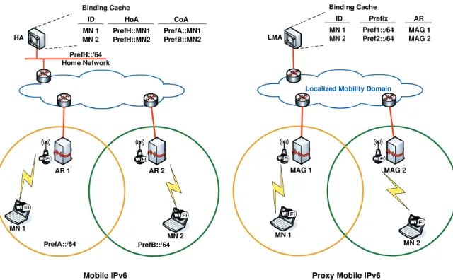
Most of current mobility management solutions derive from Mobile IPv6 (MIPv6) [47], the first mobility protocol standardized by the IETF for IPv6. MIPv6 (see Fig. 1) enables global reachability and session continuity by intro-ducing the home agent (HA), an entity located at the home network of the mobile node (MN) which anchors the permanent IP address used by the mobile node, called home address (HoA). The home agent is in charge of defending the HoA’s reachability when the mobile node is not at home (i.e., where the HoA is not topologically valid), and redirecting received traffic to the node’s current location. When away from its home network, the MN acquires a tem-poral IP address from the visited network – called care-of address (CoA) – and informs the home agent about its current location by sending a Binding Update (BU) message. An IP bi-directional tunnel between the mobile node and the home agent is then used to redirect traffic from and to the MN.
While MIPv6 requires the explicit participation of the mobile node in the signaling procedures (this is referred to asclient-based mobility), there is also a family of protocols that provide mobility support without the active involve-ment of the mobile node4
(the so-called network-based mobility). The effort led to the standardization of Proxy Mobile IPv6 (PMIPv6) [26], developed as an enhancement of MIPv6. In MIPv6, the home agent is replaced by the local mobility anchor (LMA), the network entity in charge of routing data packets in uplink and downlink containing the IPv6 prefixes assigned uniquely to MNs on a per user basis, the home network prefix (HNP), and also storing the MNs’ mobility sessions information (see Fig. 1).
PMIPv6 evolved from MIPv6 by relocating relevant functionality for mo-bility management from the MN to a network node, called the mobile access gateway (MAG), which is the first IP hop and default gateway seen by the terminal. In PMIPv6 indeed, mobility is transparent for MNs: the network learns through standard terminal operation, such as router and neighbor dis-covery [45], about MN’s movements and coordinates routing state informa-tion using Proxy Binding Update (PBU) and Proxy Binding Acknowledgment (PBA) messages. The former is sent by the mobile access gateways to the local mobility anchor to indicate the mobile node’s location, and the latter is sent as a response to ensure that the procedure succeeded. The LMA stores a binding cache entry (BCE) containing the MN’s identifier, its prefix and the serv-ing MAG’s address, called proxy care-of address (Proxy-CoA). Users’ traffic is encapsulated between the LMA and the Proxy-CoAs. The set of deployed MAGs and the corresponding LMA forms the localized mobility domain, in which mobility is completely transparent to the IP stack of the mobile nodes. Existing standardized IP mobility solutions come at the cost of handling operations at a central point – the mobility anchor – and burdening it with data forwarding and control mechanisms for a great amount of users. The use of a centralized IP mobility approach brings several limitations:a)sub-optimal routing, as traffic always traverses the central anchor, leading to paths that
4
are, in general, longer than the direct one between the mobile node and its communication peer;b)scalability problems, as existing mobile networks have to be dimensioned to support all the traffic traversing the central anchors, and the anchor itself has to be powerful enough, and;c)reliability, as the central entity is a potential single point of failure.
In order to address these limitations – which will soon start becoming an operational problem for large-scale mobile network operators – a new paradigm has gained momentum recently: the so-called Distributed Mobility Manage-ment [12,13]. DMM basically develops the concept of a flatter system, in which the mobility anchors are placed closer to the user, distributing the control and data infrastructures among the entities located at the edge of the access net-work [6]. In the next subsection, we provide an overview of existing DMM proposals.
3 Related work
A key distinguishing feature of a mobility protocol is the main entity in charge of performing the operations on the mobile side. This is the basis for the classi-cal division in client and network-based solutions, which also holds for DMM. However, in DMM we can also categorize network-based solutions according to the level of distribution of the control plane [12, 55]:
– Partially distributed solutions, which are characterized by completely dis-tributing the data path among several anchors deployed closer to the end user, but still keeping the control plane centralized.
– Fully distributed solutions, which completely distribute both the data and control planes (there is no centralized control entity).
In addition to classifying solutions as client or network-based, given the amount of different DMM solutions that can be found already today, we pro-pose an additional categorization: i) clean-slate approaches, proposing novel network architectures, as opposed to the traditional evolutionary ones that usually do not tackle the root of the problems;ii) architecture-dependent so-lutions, such as the different efforts initiated in the 3GPP to offload and/or anchor some traffic flows closer to the user [59]; iii) peer-to-peer (P2P) ap-proaches, distributing the mobility management functionality across a P2P network; andiv)solutions based on or extending existing IETF protocols [11].
3.1 Clean slate approaches
node and Border Gateway Protocol (BGP) signaling to update the internal routing within the domain. Global roaming is also supported by issuing BGP route updates between several Autonomous Systems (ASs). Although the pro-posal has been discussed within the IETF, a deep performance analysis is still missing. Regarding our other classification criterion, this solution can be con-sidered as client-based, as the mobile node has the responsibility to update its location in the DNS server. Note, however, that it is also partially network-based, as the routing is updated based on BGP signaling exchanged between the routers.
Dynamic Mobility Anchoring (DMA) [7] is a generic solution in which mobility management is offered on a per IP flow basis. Indeed, the design en-compasses two roles for an access node, depending on the service offered to the data flows generated by an MN: first, the access node can behave as a visited access node (VAN) when the functionality provided to the MN includes only the provision of IP connectivity. Second, an access node can become an anchor access node (AAN) when it is in charge of anchoring MN’s IP flows after it has moved to a different VAN. Packets arriving at the AAN are forwarded to the correct VAN by means of an IP tunnel. This tunnel is established without requiring any extra signaling with the access nodes. A VAN learns the corre-sponding AAN through packet inspection of uplink traffic. Similarly, an AAN learns the current VAN when receiving encapsulated traffic. In order to address the situation in which there is no uplink traffic, the mobile node is required to send uplink void packets to timely recover connectivity with an AAN. The side effect of this approach is the introduction of unnecessarily latencies at han-dover execution. This proposal is evaluated in [8] through simulations, but no validation via implementation is documented. This design is extended in [43] to support a prefix relocation mechanism, capable of relocating the prefixes used by the mobile node to prefixes allocated to the serving access router. This requires mobile node modifications to indicate to the network the best moment to perform the relocation.
In [39], authors propose an architecture called Access Independent Mobile Service (AIMS) to improve scalability of the network management service. The proposal is a network-based mobility management protocol where the date plane and control plane are decoupled. Data plane nodes run mobility control functions that are in charge to establish the data paths to transport users’ traffic, for instance creating IP in IP tunnels in case a handover takes place. This work can be counted in the partially distributed category, because the control plane functions rely on the Mobility Information Control Server (MICS), that acts as a central controller.
kept constant. The functionality provided by HIMALIS resembles classical ap-proaches such as the Host Identity Protocol (HIP) [27] or SHIM6 [22], which are not just a proposal to enable mobility management, but rather a new network architecture. In the same way as the HIP/SHIM6 approaches, the main drawback of HIMALIS is on the difficulties to deploy it, given that the hosts’ IP stack is considerably changed. A similar approach is followed in [58], where the Locator/Identifier split is obtained through the use of the Locator Identifier Separation Protocol (LISP) [20].
3.2 Architecture dependent solutions
Regarding the second category, architecture dependent solutions, it is worth mentioning the relevance of the work being performed in the 3GPP along the lines of flattening the network and distributing the anchors. The 3GPP is currently looking for solutions specifically tailored at reducing the volume of user data traffic traversing operators’ core networks, by providing enhanced mechanisms for local breakout and offloading. There are several standardiza-tion efforts, such as Selected IP Traffic Offload (SIPTO) and Local IP Access (LIPA) [1], or its extension to provide improved mobility capabilities: LIPA Mobility and SIPTO at the local Network (LIMONET) [2].
Hahnet al.propose in [28] and [29] two complementary solutions for packet data network gateway (P-GW) relocation within the 3GPP Release 10 speci-fication. The main idea proposed by both works is the definition of new mech-anisms for application aware non-optimal path detection.
Additionally, the work in [5] explores the deployment of client and network based DMM solutions in the EPS architecture, providing a detailed description of the required operations and the re-use of the architectural elements and interfaces.
3.3 Peer-to-peer approaches
One of the key aspects of the DMM concept is the distribution of the mo-bility management functionality across multiple entities. Peer-to-Peer (P2P) paradigms naturally envisage the interaction of such entities.
In [19], the authors present m-Chord, a protocol used to distribute the home agent and foreign agent functionality of Mobile IPv4. Their performance analysis concludes that in some cases their solution performs even better than standard Mobile IP, although in the general case, there is a performance draw-back from the use of the P2P technology.
CNs to timely inform them about the new mobility parameters. The authors argue that one of the main drawbacks of using P2P overlays for mobility man-agement is the lack of coherence between the overlay and the actual physical topology of the nodes. Hence they propose to extend the P2P protocol to con-sider physical information through a Markov decision process, optimizing the update and query performance.
In [21], a new mobility management protocol based on Distributed Hash Tables (DHT), called Distributed IP Mobility Approach (DIMA) is presented. The protocol is similar to Mobile IP but the home agent functionality is split and spread across different nodes that share a common binding distributed database. The data traffic towards the mobile node is intercepted by one of these nodes, which acts as home agent, anchoring the mobile node’s home ad-dress. The distributed mobility is achieved by relocating the nodes acting as distributed home agents, closer to the mobile nodes. Differently from MIPv6, the MN does not take active part in handling location updates, as the set of home agents are in charge of transmitting the Binding Update and Acknowl-edgment signaling.
Finally, the work [56] also describes a DMM solution that leverages a DHT storing the MNs’ ID/location pairs. Nevertheless this can be accounted as a client-based solution, because the entities located at the edge of the net-work are responsible to handle the MN’s mobility context coordinated by the messages exchanged with the MN itself, which employs a dedicated hand-off module. The session continuity during handover is granted by the bi-casting mechanism. Authors claim that their DMM solution is less demanding than Fast Handover MIPv6 (FMIPv6) [35] in terms of signaling cost.
3.4 Extension of existing protocols
There are several benefits inherent to theextension of already established pro-tocols to support DMM, such as an easier backwards compatibility.
DMM approaches focusing on Mobile IPv6 based solutions try to reduce the impact of the triangular routing on the overall performance. In [42], the ADA (Asymmetric Double Agents) extension to Mobile IP is presented to optimize handover latency and communication delays. These improvements come at the cost of introducing two new entities in the network, the local mobile proxy (LMP), that takes care of the functionality of the home agent in Mobile IP, but is located closer to the mobile node; and the correspondent mobile proxy (CMP), which is located near the correspondent node to provide an optimized route towards the LMP.
Last, but not least, works based on Proxy Mobile IPv6 are mainly focused on providing route optimization mechanisms between mobile access gateways. In [10], authors perform an analysis of the different mobility functions provided by PMIPv6, to then propose a solution splitting these functions across several nodes in the network. Nevertheless, the proposed solution uses for the actual routing of the flows a centralized approach, not providing local breakout of the connections, hence no real distributed mobility is achieved.
In [18], PMIPv6 route optimization is proposed. In this solution, the MAGs serving the MN and CN leverage on the information stored at the LMA to establish a direct tunnel between them, so a better path can be used for the communication. This mechanism still makes use of a tunnel for the whole duration of the data session. The solution is only applicable to the case in which the CN is also attached to the same PMIPv6 domain than the mobile node.
Some of the previously highlighted drawbacks are partly mitigated by the solution proposed in [53], where a different Route Optimization technique for PMIPv6 is discussed. The proposed protocol either needs the CN to be con-nected to the PMIPv6 domain or to be able to interpret some modified PMIPv6 signaling messages.
The proposal described in [54] suggests to split the functionality of the localized mobility anchor (LMA) of PMIPv6 into two distinct nodes: a control plane LMA (CLMA) and a data plane LMA (DLMA). The former maintains the mobility sessions for the MNs, whereas the second is the anchor for the MNs’ traffic. The CLMA also assigns the most suitable DLMA to the MNs. This proposal relieves the LMA’s burden, but, in general, does not fit for flat architectures, as the DLMA/MAG hierarchy is preserved, along with the tunnels, which are established for the whole duration of a data session. The solution, however, envisions an operating mode by which, if the MN and CN are under the same CLMA’s administration, route optimization can be set up between the corresponding MAGs.
Three mobility schemes are proposed in [32]: signal-driven PMIPv6, data-driven distributed PMIPv6 and signal-data-driven distributed PMIPv6 which ex-plore partially and fully distributed solutions. The three mechanisms rely on control/data split (for the partially distributed solution) and multicast or peer-to-peer communication (for the fully distributed one) to route the data towards the mobile node through the optimal path.
In the article [9], the authors present an extension for Proxy Mobile IPv6 that enables the local mobility anchor to select an entity to handle a given mobile node’s flow. The anchoring function will follow the mobile node as it roams across the mobility domain. The new entity in charge of performing route optimization between the MAGs is called intermediate anchor (IA). This entity is in charge of establishing tunnels with the old and the new MAGs, hence providing connectivity between them. The main problem of this solution is that it cannot provide the optimal path, but just an approximate one.
capable access routers (called MARs) that exchange PBU and PBA messages to update the MN’s location and IP addresses. MARs also interact with a central database to retrieve the mobility sessions and coordinate the routing state for the MNs. An analytic evaluation of such protocol is provided in [3].
Last, the following two articles envision a DMM-like scheme for the NEMO basic support protocol [16]. In [40], many distributed home agents (DHA) are deployed to facilitate a mobile router to establish an optimized path with the correspondent node. The coordination of the home agents is achieved through the home agents location registration agents (HALRA), which are responsible also for assigning an HA to the mobile router.
Conversely, the authors of [17] propose to use a PMIPv6-based DMM so-lution similar to [48] to provide mobility support to a network moving around the mobility domain, for instance for an automotive scenario.
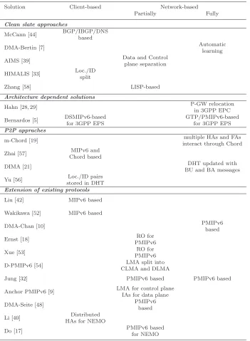
To sum up this review of related DMM approaches, Table 1 presents the summary of the different solutions covered in this section, highlighting their main characteristics and classifying them following the proposed taxonomy.
4 HDMM: Hybrid DMM for future mobile network operators
In this section we describe our proposal, called HDMM: Hybrid Distributed Mobility Management for future mobile network operators. It has two main characteristics. On the one hand, it is based on combining a client and a network-based approaches, as we argue this provides operators with a great flexibility and freedom to deploy different configurations of the solution (i.e., different scenarios impose different requirements, which can be more easily met by complementary mobility approaches). Note that this is in line with current 3GPP architectures, in which both network and client-based centralized IP mobility approaches co-exist. On the other hand, our solution is based on extending/evolving current standardized solutions, namely Mobile IPv6 and Proxy Mobile IPv6, because we believe this represent the most feasible and cost-effective solution for both operators and vendors. This allows to build the DMM framework on top of existing product lines, network deployments and benefit from existing expertise in setting up and running standardized mobility protocols.
Network-based mobility approaches do not require any specific IP mobility support on the mobile node, which allows for an easier deployment in some sit-uations. On the negative side, this kind of approach makes more challenging inter-technology mobility and inter-domain roaming, as some security asso-ciations have to be in place, and this is not always possible when crossing operator boundaries. HDMM extends Proxy Mobile IPv6 to operate in a dis-tributed way, which can include control and data planes, or just data plane, as will be described later in this article.
Table 1 Summary chart of main DMM proposed solutions
Solution Client-based Network-based Partially Fully
Clean slate approaches
McCann [44] BGP/IBGP/DNS based
DMA-Bertin [7] Automatic
learning
AIMS [39] Data and Control
plane separation
HIMALIS [33] Loc./IDsplit
Zhang [58] LISP-based
Architecture dependent solutions
Hahn [28, 29] P-GW relocation
in 3GPP EPC Bernardos [5] DSMIPv6-based GTP/PMIPv6-based
for 3GPP EPS for 3GPP EPS
P2P appraches
m-Chord [19] multiple HAs and FAs
interact through Chord Zhai [57] MIPv6 and
Chord based
DIMA [21] DHT updated with
BU and BA messages
Yu [56] Loc./ID pairs stored in DHT
Extension of existing protocols
Liu [42] MIPv6 based
Wakikawa [52] MIPv6 based
DMA-Chan [10] PMIPv6
based
Ernst [18] RO for
PMIPv6
Xue [53] RO for
PMIPv6 D-PMIPv6 [54] LMA split into
CLMA and DLMA
Jung [32] PMIPv6 based PMIPv6 based
Anchor PMIPv6 [9] LMA for control plane IAs for data plane
DMA-Seite [48] PMIPv6
based
Li [40] Distributed HAs for NEMO
Do [17] PMIPv6 based
for NEMO
inter-domain mobility becomes easier, as there is no need for deploying security associations between network entities belonging to different operators, just between the mobile node and the home agent. In this case, HDMM extends Mobile IPv6 to support its distributed operation, as well as its combination with the network-based operation mode, for those cases in which this feature is required.
Note that even though HDMM comprises two solution components, each of them can be used independently. Before describing how each component works, we introduce below some common terminology that is used throughout the article:
– Distributed Anchor Router (DAR). It corresponds to the first IP router (with mobility functionality) which a mobile node attaches to. Upon at-tachment, the distributed anchor router provides the mobile node with a topologically correct IPv6 address/prefix. In case the mobile node later moves to a different location, this DAR is in charge of ensuring the reacha-bility of the previously delegated address/prefix. In this way, the DAR can be actually considered as a distributed version of the anchors defined by the classical centralized mobility protocols: the home agent and the local mobility anchor.
– Serving DAR (S-DAR).This term is used to refer to the distributed anchor router where the mobile node is currently connected. Note that the mobile node may have visited different DARs before, and might still be using addresses configured from some of them. As described later, this entity can be considered as a modified version of the mobile access gateway (for the case of the network-based component of HDMM). In this article, we consider for simplicity, that a mobile node can only be attached to a single serving distributed anchor router at a time.
– Previous DAR (P-DAR). This term denotes a distributed anchor router that has been previously visited by a mobile node and which is still an-choring an IP address used by one or more active IP flows of the mobile node. For a given mobile node, there might be multiple P-DARs active at a time.
4.1 Client-based HDMM
DAR1
(a) (b)
(c) (d)
CN1
CGA-CoA1
MN
Internet
CN1
MN DAR1
Internet
DAR2
MN
IP-in-IP Tunnel
BU/BA
CN1
DAR1
Internet
DAR2
MN
IP-in-IP Tunnel
CN2
CGA-CoA2
CGA-CoA1
CGA-CoA1
CN1
DAR1
DAR2
MN CN2
CGA-CoA2
CGA-CoA1
DAR3
BU/BA BU/BA
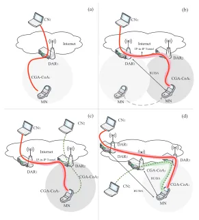
Fig. 2 HDMM client-based component operation.
4.1.1 Solution overview
requiring mobility service are maintained, while new sessions can make use of the last configured IPv6 address (i.e., the one delegated by the S-DAR), hence using an IPv6 address that is topologically correct at the current mobile node’s location. Compared with regular Mobile IPv6, client-based HDMM introduces the use of several (distributed) home agents, and the additional intelligence on the mobile node to be able to simultaneously manage several home addresses and tunnels, as well as to effectively select the best possible source address for new connections. Note that the operations performed by the mobile node are different from what is standardized in the IP flow mobility (IFOM) extensions, namely [50, 51], as in the DMM case multiple anchors are involved, while in the IFOM case only one anchor (the home agent) is involved, but the different sessions are delivered to the mobile node via multiple network accesses.
Although the operation of client-based HDMM and Mobile IPv6 are very similar, the distributed operation of HDMM might pose additional concerns in terms of security. Securing the communication between the mobile node and every P-DAR through IPsec [15], as done in traditional Mobile IPv6, would be challenging due to the large number of required security associations (note that every DAR may be playing the role of P-DAR). In order to over-come this problem and provide authentication between the distributed anchor routers and mobile nodes, we propose the use of cryptographically generated addresses (CGAs) [4], as introduced in [36]. CGAs are basically IPv6 addresses for which the interface identifier is generated by computing a cryptographic one-way hash function from a public key and the IPv6 prefix. The binding be-tween the public key and the address can be verified by re-computing the hash function and comparing the result with the interface identifier. To authenti-cate a message, the packet is signed with the corresponding private key, hence the receiver is able to authenticate the message with the knowledge of the address and the public key. CGAs are a powerful mechanism allowing packet authentication without requiring any public-key infrastructure, and hence it is well-suited for this application.
We also suggest an lighter mechanism to authenticate signaling messages, based on the use of a Permanent Home Keygen Token (PHKT). This token is forwarded by a P-DAR to the mobile node in the Binding Acknowledgment message sent in reply to the first BU. For any subsequent movement requiring to maintain the reachability of an address for which the MN has already sent a BU, the following BU messages can be secured using the PHKT exchanged before, reducing the computational load at the receiving P-DAR.
node can now send a BU using both Home and CoA Keygen tokens to proof its reachability at both the HoA and the CoA. The message and the knowledge of both tokens is a proof that the mobile node is the legitimate node who has sent the Binding Update message and also is reachable at the CoA indicated. This last security improvement incurs in a performance penalty, namely an increase in the handover delay. The enhanced security approach requires four messages to be exchanged between the mobile node and the P-DAR, instead of the two messages of the original solution. In terms of handover delay, this increases the latency by a factor of two, as the new solution requires an amount of time equal to two MN-to-P-DAR round trip times (RTTs) to conclude, instead of just one. The performance of the solution is analyzed in more detail in Section (Section 5).
Fig. 2 shows an example of the operation of client-based HDMM: a mobile node first attaches to a distributed anchor router (DAR1), configures a locally anchored IP address, starts a new session withCN1and then moves toDAR2, where a new communication with a different CN (CN2) is started, using the IP address locally anchored at the new DAR.
Note that the operation of HDMM is fully compatible with legacy cen-tralized home agents, as it might be required for some traffic to traverse the mobile network operator’s core (e.g., because of service agreements, location privacy or simply for sessions that are known in advance to be long-lived, so it is more efficient to anchor them centrally).
4.2 Network-based HDMM
This section summarizes the operation of the network-based component of HDMM, which is basically a distributed version of Proxy Mobile IPv6. Both the MAG and LMA functions are implemented by the distributed anchor router (DAR). For additional details, the reader is referred to [25].
The network-based HDMM component is characterized by the split be-tween control and data planes. In the following sections we present two ap-proaches for the control plane implementation: i) a partially distributed ap-proach, which relies on a central entity to keep track of the movement of the users and the previously visited anchors;ii)a completely distributed version, in which the control plane does not use any central entity and signaling is exchanged between the involved anchors instead. Both approaches follow the same data forwarding scheme, which is illustrated next.
4.2.1 Data plane management
start new IP flows, so packets benefit from optimal routing. However, ongoing data sessions still need reachability of the old address. Hence a bi-directional tunnel is setup between the S-DAR and the previous DAR to not disrupt the communication. Borrowing PMIPv6’s definition, the S-DAR behaves as a MAG, and the P-DAR as an LMA. The MN may have hence a number of flows directly routed by the S-DAR to and from the global Internet without encapsulation, and another set of streams anchored at the P-DAR. Depending on the previous MN’s movement history and the active sessions, this situation might be replicated for multiple P-DARs.
At the control plane level, the key element to achieve this traffic config-uration is to let the S-DAR interact with the P-DARs so that the correct routing state can be set up. This concept leads to the definition of a partially distributed scheme first.
4.2.2 Partially distributed approach
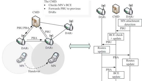
This solution leverages on a central entity to store the mobility sessions and maintaining the state about S-DAR and P-DARs for all the MNs in the do-main. This entity is called central mobility database (CMD), and basically implements all the tasks related to keeping the Binding Cache up to date, as a regular PMIPv6 LMA does, updating its entries with the information received from the DARs. However, its operation differs from the one of a legacy LMA in that the CMD does not perform any data forwarding task, therefore users’ data traffic does not traverse it.
Similar concepts can be found in the related work [17, 48]; a server acting as mobility/policy store is queried by the serving anchor, which interacts with the anchors indicated in the response to set up the proper routing configura-tion. A similar functionality can be found in our scheme, although with a key difference. In our proposal, the central server (the CMD) does not passively provide the response, but it rather takes an active role forwarding the mes-sages to the MN’s P-DAR(s), since it is the entity in possession of the whole picture in terms of involved P-DARs and prefixes allocated.
PBA PBU MN attachment
detection
BCE creation PBU/PBA
)ORZXVLQJ01¶V Pref1::MN
CMD
1st Attachment
MN CN1
DAR1
DAR2
DAR3
DAR1 CMD
Fig. 3 Partially distributed network-based HDMM: initial registration.
PBU
PBA
MN attachment detection
BCE check + update PBU
Routes update
BCE update
Routes update PBA CMD
MN
DAR1 DAR2
DAR3
MN PBU/PBA
PBU/PBA
Handover
DAR1 CMD DAR2
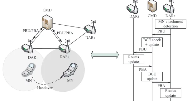
Fig. 4 Partially distributed network-based HDMM: CMD behaves as PBU/PBA relay.
created and unicasts a router advertisement (RA) to the mobile node, including the IPv6 prefix reserved before, that is used by the MN to configure an IPv6 address (e.g., with stateless auto-configuration). Since this address is locally anchored at the S-DAR, no encapsulation nor special handling is required to route packets of IP flows started there.
When a handover occurs, there are several possible signaling schema that can actually be used by the DARs to interact with the CMD and set up all the required state in the network. Each approach assigns a different role to the central mobility database, with different pros and cons associated, in terms of handover latency and signaling overhead:
– the CMD behaves as a DAR locator,
– the CMD behaves as a PBU/PBA proxy.
The CMD behaves as a PBU/PBA relay: When the MN moves from its cur-rent access and attaches to another DAR (see Fig. 4), say DAR2 (now the S-DAR), the L3 handover is handled in 4 phases:
1. DAR2 reserves an IPv6 prefix (Pref2) from its local pool, storing it in a temporal BCE, and sends a plain PBU to the CMD for registration (as the initial registration phase).
2. Upon PBU reception and binding cache lookup, the CMD retrieves an already existing BCE for the MN. The BCE indicates a DAR’s address in the P-CoA field, so the CMD forwards the received PBU message to it (in our example DAR1), appending to the message the S-DAR’s global address (DAR2). The P-CoA is changed indicating the new S-DAR’s address. 3. Upon reception of the PBU from the CMD, DAR1 sets up its end-point
for the bi-directional tunnel towards DAR2 and adds the required rout-ing entries for Pref1. DAR1 informs the CMD that these steps have been successfully performed by sending a PBA message.
4. The CMD, after receiving the PBA, adds an item in the BCE called P-DARs list. An entry of the P-P-DARs list is composed by the pair P-DAR’s address and the prefix it allocated to the MN (in our example DAR1’s address and Pref1). Finally, the CMD sends a PBA to the current S-DAR, which includes the P-DAR’s address and the associated anchored prefix. This message enables the S-DAR to finally establish the correct routing state, i.e., the bi-directional tunnel with the P-DAR (DAR1) and the rout-ing entries for Pref1.
5. The S-DAR advertises the local anchored prefix to the MN, and sends an additional RA including the old prefix but indicating a non zero valid lifetime and a zero preferred lifetime. In this way the old address can be correctly used to terminate old data sessions, whilst it is deprecated for new ones, forcing the MN to pick the address advertised by the S-MAR. Fig. 5 illustrates how old and new IP flows are routed in the domain. Any subsequent mobile node’s handover follows the same procedure, involving all the P-DARs that are anchoring active flows incrementally. Indeed, when the CMD receives the first PBU message from the S-DAR, it forwards a copy of the message to the P-CoA and to all the P-DARs indicated in the P-DAR list. All these DARs reply back with a PBA message to the CMD, which then aggregates all the messages into a single PBA sent to the new S-DAR, hence the routing state has been re-configured in the whole domain.
)ORZXVLQJ01¶V Pref1::MN
)ORZXVLQJ01¶V Pref2::MN CMD
MN DAR1
DAR2
DAR3
CN2
CN1
IP-in-IP tunnel
DAR1: Creates tunnel and routing state
based on Binding Entry rules
Fig. 5 Partially distributed network-based HDMM: data flow.
PBU
PBA
MN attachment detection
BCE check + update PBU
Routes update
BCE update
Routes update
PBA CMD
MN
DAR1 DAR2
DAR3
MN PBU/PBA
PBU
Handover
DAR1 CMD DAR2
PBA
The CMD:
x &KHFNV01¶V%&(
x Forwards PBU to previous DARs
Fig. 6 Partially distributed network-based HDMM: CMD behaves as DAR locator.
to the S-DAR the prefix it is anchoring for the MN. A similar message is sent to the CMD too, to maintain the consistency in the database. The routing state can be recovered and the procedure is expected to terminate quicker than the previous scheme. Fig. 6 illustrates the new signaling sequence, while the data forwarding remains unaltered.
PBU
PBA
MN attachment detection
BCE check + update
Routes update
BCE update
Routes update CMD
MN
DAR1 DAR2
DAR3
MN PBU/PBA
PBU/PBA
Handover
DAR1 CMD DAR2
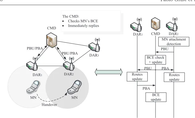
The CMD:
x &KHFNV01¶V%&(
x Immediately replies
PBU PBA
Fig. 7 Partially distributed network-based HDMM: CMD behaves as PBU/PBA proxy.
whole MN’s picture, so the serving DAR is notified immediately with a PBA message, including the necessary parameters. In parallel, a PBU message is sent by the CMD to the P-DARs notifying them about the new mobile node’s location, so they can establish the required tunnels and routing entries on their side. Every P-DAR, after completing the update, sends a PBA message to the central mobility database to indicate that the operation is concluded and the state has been updated. This scheme is depicted in Fig. 7, where, again, the data forwarding remains the same.
4.2.3 Fully distributed approach
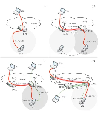
With this approach, the prefix assignment and routing configuration concepts are identical to the schema previously presented, but with one key difference: the PBU/PBA handshake takes place between the new S-DAR and the P-DAR(s) without the involvement of other entities.
The illustrations in Fig. 8 show how an IP flow is handled when generated at the initial DAR (Fig. (a)), how the flow is routed after a handover (Fig. 8-(b)) and how a second flow started at the new S-DAR is routed in the network as compared with previous flows (Fig. 8-(c)). Finally, Fig. 8-(d) exhibits the handover to a third (and in general, to all subsequent) DAR.
The key point is how the S-DAR finds out if the attached mobile node has any active flows anchored at previously visited P-DARs, and, if so, which these P-DARs are, and what IPv6 prefixes they are anchoring. We here propose the following alternative mechanisms:
DAR1
(a) (b)
(c) (d)
CN1
Pref1::MN
MN
Internet
CN1
MN
DAR1
Internet
DAR2
MN
IP-in-IP Tunnel
PBU/PBA
CN1
DAR1
Internet
DAR2
MN
IP-in-IP Tunnel
CN2
Pref2::MN
Pref1::MN
Pref1::MN
CN1
DAR1
DAR2
MN CN2
Pref2::MN Pref1::MN
DAR3
PBU/PBA
PBU/PBA
Fig. 8 Fully distributed network-based HDMM: protocol operation.
the network. Unfortunately this approach might not provide a good per-formance in terms of handover delay and adds unnecessary signaling in the network.
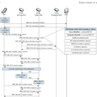
Fig. 9 Fully distributed network-based HDMM: IEEE 802.21-aided message exchange se-quence during handover.
completed in a controlled and assisted way, according to the make-before-break philosophy. Additionally, the IEEE 802.21 suite is intended to allow inter-technology handovers, providing support to mobile nodes roaming within a heterogeneous environment. Fig. 9 presents the detailed procedure including the IEEE 802.21 signaling required to perform a fully distributed network-based handover. In the figure, DARs and Points of Service (PoS) are co-located, whilst Points of Attachment (PoA) are omitted to keep the chart simple. Indeed, the diagram highlights the message exchanges between the MN and the S-DAR, and also among DARs.
CN1
DAR1
DAR2
MN
CN2 Pref2::IP2 Pref1::IP1 DAR3
CN1
DAR1
CN2
Pref2::IP2 Pref1::IP1
MN Operator 1
Operator 2 DAR X
DAR2
Inter-Operator Handover
Fig. 10 An example use-case of HDMM: inter-operator mobility.
4.3 Hybrid DMM: combining network and client-based mobility
The network and client-based components of HDMM can be used as stan-dalone solutions. However, we argue that future mobile network operators can benefit from a framework allowing a seamless integration of both solutions (some example scenarios were mentioned in Section 1). Actually, current mo-bile operator architectures, such as the 3GPP one, support both network and client-basedcentralized mobility solutions, offering in this way more flexibil-ity to the operator. Therefore, HDMM basically takes this situation one step further, by also proposing a framework that includes network and client-based distributed mobility approaches.
We take inter-domain mobility as one representative scenario of combined HDMM deployment and use it in this section to explain how our proposed hybrid scheme works and the advantages it brings to mobile operators.
Fig. 10 shows an example of hybrid DMM operation. A mobile node first attaches to a mobile operator and benefits from network-based distributed mobility management (by using either the partially or the fully distributed variant described in Section 4.2).
address configured on the new domain as care-of address where active ses-sions anchored elsewhere can be redirected. This operation can be executed exploiting enhanced features of the terminal’s connection manager.
The connection manager is a software construct widely available in most of today’s portable devices. In the last years, and due to the availability of different networks where the mobile nodes can connect to, this piece of software has gained quite a lot of relevance. The connection manager, upon detection that the target point of attachment does not belong to the home operator or it does not support DMM, can activate the mobility client at the mobile node. Let’s consider the example shown in Fig. 10. A mobile node has been moving within its DMM-enabled home domain. In this example, we consider that the DMM solution used is network-based, as this represents the most complex situation, as we explain next. In this case, there are two possible solutions when the mobile node performs an inter-operator hand-off: i) the connection manager of the mobile node has tracked all the active P-DARs (i.e., all the DARs visited by the MN in the home dome domain anchoring an IP address used by an active session), or ii) the connection manager is only aware of the last S-DAR it was attached to before roaming to a new domain. In the former case, which requires a bit more of intelligence in the connection manager, the mobile node can just follow the client-based approach and update each of the P-DARs with its current location by sending a BU message. Note that this results in optimizing the path followed by data traffic between each of the P-DARs and the current location of the mobile node5
. In the later case, the mobile node just updates its location on the last visited S-DAR (and sets up a tunnel), which then takes care of forwarding all the traffic received from the active P-DARs to the MN, using the tunnel established with the MN. This requires less complexity on the connection manager, but does not fully optimize the data path between the active P-DARs and the current location of the mobile node (i.e., packets have to traverse to chained tunnels: one from the MN to the last visited S-DAR, and one from this S-DAR to the corresponding P-DAR). Fig. 10 illustrates the casei).
Note that if the new domain also supports HDMM, then subsequent han-dovers within that domain could be transparently managed by the network-based mobility solution in place, without requiring any action on the client-mobility stack running on the mobile node6
.
The previous example clearly shows how each distributed anchor router can be simultaneously playing – on a prefix basis – the roles of plain IPv6 access router (for prefixes locally anchored used by attached mobile nodes), as local mobility anchor (for prefixes locally anchored that are in use by mobile nodes
5
This does not optimize the overall route between the mobile node and the peers it is communicating with. This fully optimized route can be achieved if the communication peer supports the correspondent node Mobile IPv6 route optimization (RO) functionality.
6
which are no longer directly attached), as mobile access gateway (to enable address continuity for prefixes anchored at a different DAR) and as home agent (for locally anchored prefixes used by mobile nodes which are no longer directly attached and that are using the client-based HDMM component).
5 Analytic evaluation
This section provides the analytic evaluation of HDMM. The analysis is con-ducted considering the following three key performance metrics of an IP mo-bility protocol:i)packet and signaling overhead,ii)handover latency, andiii) end-to-end delay. Similar to the works [30] and [38], where different mobility protocols are compared, in the next paragraphs we carry out our analysis with respect to Mobile IPv6 and Proxy Mobile IPv6.
5.1 Overhead analysis
Both client and network-based HDMM enable the use of a locally locally an-chored address provided by the serving DAR for new MN’s communications, thus benefiting from no additional encapsulation. This is a clear performance advantage compared to centralized schema, where tunnel ling is always used (unless the mobile node is at home, and only for the case of Mobile IPv6).
Nowadays, users enjoy from a very large catalog of mobile applications. Some of them do not require IP address continuity, meaning that the applica-tions themselves can cope with an IP address change (e.g., progressive HTTP download). This opens the door for not providing IP mobility support by de-fault to every address/service (which is the current practice), but just to those that really require it, helping in this way to reduce the overall load in the net-work’s core. This feature is known asdynamicmobility management, which is inherently supported by our HDMM approach.
In terms of packet overhead, the use of IPv6-in-IPv6 tunneling adds 40 ex-tra bytes to every packet, and it also requires additional processing resources for the encapsulation/de-encapsulation operations and for the tunnel manage-ment itself. A difference between network and client-based solutions is that the extra tunnel overhead is not present in the last hop (which is wireless) for the case of the network-based solutions, and that the tunnel operations are per-formed by (usually powerful) network nodes, without the mobile node being involved. This is important from the point of view of energy and processing power efficiency, as the mobile node is usually more limited.
We next describe our analysis of the signaling overhead. A general expres-sion of the average signaling cost for a mobility scheme is given by [49]:
CSIGNAL= 1 SMR·√M
h
(√M−1)CINTRA+CINTER i
, (1)
costs for the intra and inter-domain handover respectively. These costs are proportional tod(X, Y), distance in number of hops from a node X to a node Y7
, multiplied by the link factors τ and ω, for a wired and a wireless link respectively. Therefore, the cost for transferring a packet from the MN to the S-DAR is CMN,S-DAR = ω d(MN,S-DAR) = ω, whereas from a S-DAR to a P-DAR it isCS-DAR,P-DAR=τ d(S-DAR,P-DAR). Note, that this last value depends on the size and configuration of the network.
The signaling cost of intra and inter-domain handovers,CINTRAandCINTER respectively, depends on the mobility solution that is used. The following cases are possible:
– INTRA domain handover. Both network and client-based solutions can be used to enable intra-domain mobility. Since we are also considering the centralized schema, we have:
CINTRA =CPMIPv6 |CMIPv6 |CHDMM-net |CHDMM-client. (2)
– INTER domain handover. In this case, and for the reasons presented earlier in this article, we argue that client-based mobility is more appropriate. Therefore, we have:
CINTER=CMIPv6 |CHDMM-client. (3)
We next analyze each of these cost components, for both HDMM and the classic IP centralized mobility approaches.
5.1.1 PMIPv6
The hand-off signaling consists of a PBU/PBA handshake between the new MAG and the LMA, so the cost is given by:
CPMIPv6 = 2τ d(LMA,MAG). (4)
5.1.2 MIPv6
In plain Mobile IPv6 there is a single BU/BA exchange per handover (we just assume no route optimization support is used for simplicity), so the signaling cost is given by:
CMIPv6 = 2 [ω+τ d(AR,HA)]. (5)
7
5.1.3 HDMM network-based component
Partially distributed approach: Depending on the actual procedure used to update the central mobility database, the total signaling load varies:
– CMD behaves as PBU/PBA relay. Besides the handshake between the CMD and the S-DAR, there is an additional PBU/PBA exchange withn
active P-DARs. This accounts for a total number of 2n+ 2 messages:
Cpartially−relay
HDMM-net = 2τ d(CMD,S-DAR) + 2n τ d(CMD,P-DAR)
= (2n+ 2)τ d(CMD,DAR), (6)
where d(CMD,DAR) is the average distance between the CMD and the DARs in the domain.
– CMD behaves as DAR locator. In this case, the amount of PBU and PBA messages is 3n+ 1: a first PBU message sent by the new S-DAR, plusn
copies sent by the CMD to the active P-DARs, and 2nPBA messages sent back by the P-DARs to the CMD and the S-DAR:
Cpartially−locator
HDMM-net =τ d(CMD,S-DAR) + 2n τ d(CMD,P-DAR) + +n τ d(S-DAR,P-DAR). (7)
– CMD behaves as a PBU/PBA proxy. Apart from the re-ordering, the num-ber of messages sent is identical to therelay case, 2n+2, thus Eq. (6) holds in this case as well:
Cpartially−proxy
HDMM-net =C
partially−relay
INTRA . (8)
Fully distributed approach: Regardless the method adopted to learn that a handover occurred, the S-DAR has to perform a PBU/PBA handshake with
nactive P-DARs. Beingnthe number of IPv6 addresses that need to be kept reachable anddS−DAR,P−DARthe average number of hops, the result is a total of 2ncontrol messages:
CHDMM-netf ully = 2n τ d(S-DAR,P-DAR). (9)
5.1.4 HDMM client-based component
The client-based component of HDMM involvesnBU/BA exchanges (plus the CoTI/CoT ones in case of additional security), wherenis the number of IPv6 addresses that need to be kept reachable. This accounts for a total of 2n(+2n
CHDMM-client = 2n[ω+τ d(S-DAR,P-DAR)] w/o add. security, (10)
CHDMM-client = 4n[ω+τ d(S-DAR,P-DAR)] w/ add. security.
Note that this analysis assumes the solution variant in which the connection manager of the mobile node is capable of keeping track of every active P-DAR, so it can update all of them. With the other variant, in which only the previous S-DAR is updated, the cost is reduced.
5.1.5 Comparison
From the previous analysis, we can observe that the HDMM solutions are more costly in terms of signaling, as they introduce more messages than the centralized solutions because there are more anchors to update. However, if we focus on the network-based solutions, the cost of a fully distributed scheme may be close to the PMIPv6 one, for scenarios in which there are very few active P-DARs and they are much closer to the S-DAR than the LMA to the MAG.
If we focus on the client-based solutions. HDMM introduces more traffic at the control plane level, but it allows using optimal or close to optimal routes for data traffic. On the other hand, MIPv6 requires less signaling but all the user’s data need to traverse the home agent. The route optimization procedure enables the MN to use an optimal path with the CNs, but all the CNs need to be notified with some signaling, leading to an equal or larger number of control messages than client HDMM.
5.2 Handover latency
We define the handover latency as the time during which a node does not have IP connectivity as a result of a change of point of attachment. During this time, the IPv6 address that was being used by the mobile node is not usable. Multiple operations are performed during this process, such as layer-2 attachment, movement detection, address configuration and duplicate address detection, and the mobility signaling. We next briefly summarize the different components of the handover delay:
– Layer-2 handover time (Tho
L2). This is defined as the time required by the layer-2 technology to perform a handover (i.e., disconnecting from its cur-rent point of attachment and connecting to a new one).
multicasts unsolicited RA messages. Movement detection can also be as-sisted by the use of layer-2 triggers, such the ones implemented by IEEE 802.21. In this case, the movement detection delay can be extremely low.
– IP address configuration and duplicate address detection (TDAD). This time corresponds to the configuration of the IP address based on the prefix received in the RA (i.e., the MN uses stateless auto-configuration) and the address uniqueness test in the network. Note that DAD is only used for new prefixes in the network-based approach, since old prefixes are maintained from previous allocations and do not require of new DAD processes.
– Network authentication delay (Tauth). The handover delay also depends on the particular authentication method used in the network being accessed by the user terminal.
– Mobility signaling delay (Tbinding). This is the time required to update the mobility anchor (i.e., the home agent, the localized mobility anchor or the distributed anchor router) with the new location of the mobile node (denoted by its care-of address or the associated proxy care-of address). It is highly dependent on the distance between the entities participating in the user mobility management. For client-based approaches this is the distance between the mobile node and the home agent/distributed anchor router, while for network-based approaches, this is the distance between the mobile access gateway and the local mobility anchor, or the distance between the serving DAR and the previous DAR, or the the distance between the central mobility database and the involved DARs, depending on the solution flavor.
The handover latency can be then expressed as follows:
Thandover=TLho2+TMD+TDAD+Tauth+Tbinding, (11)
in which the most relevant component for the comparison of different so-lutions isTbinding. The other delay components can be considered common to any of the analyzed mobility solutions8
. The termTbinding can be expressed, for each of the different scenarios, as follows:
– Mobile IPv6:
TbindingM IP v6=RTTMN↔HA. (12)
– Client-based HDMM:
THDM M−client
binding =RTTMN↔P-DAR. (13)
– Proxy Mobile IPv6:
TbindingP M IP v6=RTTMAG↔LMA. (14)
8
– Partially distributed network-based HDMM, CMD behaves as PBU/PBA relay:
THDM M−net−part−relay
binding =RTTS-DAR↔CMD+RTTP-DAR↔CMD
≈2·RTTDAR↔CMD. (15)
– Partially distributed network-based HDMM, CMD behaves as DAR loca-tor:
TbindingHDM M−net−part−locator = RTTS-DAR↔CMD+RTTP-DAR↔CMD+RTTS-DAR↔P-DAR
2
≈RTTDAR↔CMD+
RTTS-DAR↔P-DAR
2 . (16)
– Partially distributed network-based HDMM, CMD behaves as PBU/PBA proxy:
THDM M−net−part−proxy
binding = max(RTTS-DAR↔CMD;
RTTS-DAR↔CMD+RTTP-DAR↔CMD
2 )
≈RTTDAR↔CMD. (17)
– Fully distributed network-based HDMM:
THDM M−net−f ully
binding =RTTS-DAR↔P-DAR. (18)
For the cases of partially distributed network-based HDMM, we assume that the distance between the central mobility database and all the distributed anchor routers is approximately the same (RTTDAR↔CMD).
Comparing Eqs. (12) and (13), it is clear that the main difference between client-based HDMM and Mobile IPv6 in terms of handover delay corresponds to the distance between the mobile node and the home agent/distributed an-chor router. This is the main advantage of a distributed mobility management approach as compared with classical centralized mobility solutions, because the delay between the mobile node and its anchor is likely lower in the distributed approach (as the anchor in this case resides at the edge of the network, instead of at the core of the operator). It is also worth noting how as the mobile node gets farther away from an active previous DAR, the handover delay increases, thus HDMM is better suited for flows with short duration or mobile nodes with low mobility. This characteristic is explored in more detail in the next section.
Similarly, from Eqs. (14) and (18), we can see that network-based HDMM produces a shorter latency as long as the distance between the serving and previous DARs is shorter than the one between the MAG and LMA for the case of Proxy Mobile IPv6. This parameter strictly depends on the size of the operator’s network, but, we can safely assume that an LMA would always be always farther than active previous DARs for the case of short communications with users of limited mobility.
all the others partially distributed proposals. For all partially distributed so-lutions, the handover delay approximates to the one of Proxy Mobile IPv6: RTTLMA↔MAG. This is so because as the central mobility database is pushed into the core of the operator, the distance from the CMD to all DARs is similar.
5.3 End-to-end delay
We next analyze the delay experienced by packets exchanged between the mobile node and its communication peer (i.e., a correspondent node).
In Mobile IPv6, user data traffic always traverses the home agent, although this path may not be the shortest one between the mobile node and the cor-respondent node. This operation mode is called Bidirectional Tunneling (BT) and the resulting way of forwarding packets is known as angular routing. In this case, the end-to-end delays might be large, since the packets must go through the MN’s home network, which can be located at a long distance from the mobile node. Due to the large delays introduced by the angular rout-ing, Mobile IPv6 [47] already includes a procedure called route optimization (RO) that basically builds a secure direct path between the mobile node and the correspondent node. Thanks to the use of route optimization, packets ex-changed between the mobile and the correspondent node can flow directly through the shortest path between the two nodes, without passing through the home agent. This mechanism needs additional support from the corre-spondent node, required to enable the optimization of the path. In the case of our HDMM approach, packets flow between the mobile node and the cor-respondent node traversing the serving DAR as in the case of Mobile IPv6 in BT mode. The difference between both approaches is that in our case, DARs are expected to be located near the mobile node, hence the effect of angular routing is highly minimized, obtaining delays of the order of RO-enabled Mo-bile IPv6. As mentioned earlier in the paper, the use of DMM is better suited for flows with short duration or low mobility MNs. The reason for this is the fact that as the mobile node moves away from the serving DAR handling a flow, the inefficiency introduced by the angular routing increases.
In order to assess how far and how fast a mobile node can move, we per-formed the following analysis. Lets suppose a VoIP communication between two peers, being one of them a mobile node making using of one of the HDMM schema. Considering the maximum mouth-to-ear delay as specified in [31] of 150 ms, we can assume that Eq. (19) holds:
TCN→HOM E−AR+THOM E−AR→M N ≤150ms, (19)
in whichHOM E−ARstands for the serving DAR or HA/LMA according to the solution in place.
Let’s assume the correspondent node and the mobile node are in the same geographical region or even city. In order to model this delay, we took average values from the PingER project9
, between several client-server pairs located
9
in the same regional area. The average delay obtained corresponds to roughly 20 ms, so Eq. (19) indicates the delay between the HOME-AR and the MN is upper bounded by 130ms. If we consider the network-based HDMM solution, we can assume that the DMM domain has a good internal connectivity. In this way, we can also assume that the delay between two distributed anchor routers is similar to a local delay between two servers located in the same organization (from the PingER project this delay is on average equal to 5 ms). To simplify, we suppose that the access network is deployed in such a way that going farther away from the first DAR visited by the mobile node increases the delay in a linear way (note that this is a worst case scenario). The maximum number of hops allowed for the VoIP communication can then be derived from Eq. (19), resulting in a maximum distance of 26 hops. This number represents a limit on the diameter of the DMM domain, which depends on the access technology used.
In the case of client-based HDMM, we could follow a similar analysis but considering that the distance between the distributed anchor routers is longer than in the network-based case. If we assume a inter-DAR delay of roughly 10ms (intermediate value between a regional and local delay), our solution allows approximately 10-13 hops before degrading the VoIP call.
The same delay assumptions hold for the centralized approaches, but we have to also consider the the angular routing intrinsic to Mobile IPv6 and Proxy Mobile IPv6. For instance, we can assume that the distance between a mobile node and a correspondent node is twice the client-server distance men-tioned before: one to get to the HA/LMA, and another to reach the recipient (we can safely assume that the anchor is equidistant from the communication endpoints, as they are all located in the same region). With these assumptions, after 4/5 hops HDMM performance degrades to be the same of a centralized scheme. However, the advantage of HDMM is that when the delay becomes not tolerable, the application might be restarted, or the communication refreshed, so that the most suitable IP address can be picked, thus leading to traverse a shorter (direct) path with better delay.
6 Experimental evaluation
This section provides an experimental evaluation based on real tests conducted with an HDMM prototype. The goal is two-fold: on the one hand, to show that the designed solution is feasible in a real testbed; and, on the other hand, to assess some performance metrics.
Client-based HDMM is conceptually similar to Mobile IPv6, being the main difference the fact that the mobile node is able to simultaneously operate with multiple home addresses anchored at different home agents. Therefore, and from the point of view of performance evaluation, there is little value in developing a prototype of the client-based HDMM component, as the results would not differ from those already available for Mobile IPv6 (of course, using the same mobile node - anchor delay). Because of this, we prefer to focus or implementation and evaluation efforts on the network-based component of HDMM, which does present significant differences as compared to legacy Proxy Mobile IPv6. One of the main contributions of this study is to compare the partially and fully distributed approaches when delivering real traffic.
The prototype of network-based HDMM is written in C and runs in Linux-operated machines. It is based on the OAI PMIPv6 implementation10
, ex-tended with the new characteristics explained in Section 4.2. The testbed is composed of five Linux Ubuntu 10.04 boxes (running a Linux-2.6.32 kernel): four desktop PCs playing the role of three DARs and one CMD, plus one laptop playing the role of mobile node. In terms of connectivity between the different entities, both the central mobility database and the distributed an-chor routers are connected to the same Ethernet switch, while the mobile nodes obtains connectivity using IEEE 802.11g as wireless technology.
The partially distributed approach is implemented following theCMD as Proxy variant because it provides the quickest reaction to the handover event in terms of routing state re-configuration. Also, it yields to the least number of signaling messages exchanged.
Regarding the fully distributed approach, the complete IEEE 802.21 sig-naling is not implemented, as the messaged are exchanged before the actual Layer-2 handover, and therefore, they do not impact the performance metrics collected here. Based on that, we have only implemented a custom Layer-2 attachment and detachment detection mechanism. Nevertheless, it is worth highlighting that we are currently working together with the authors of [14] to integrate an open source IEEE 802.21 implementation (called ODTONE11
) with our HDMM prototype within the framework of the MEDIEVAL12
Eu-ropean project. Since the IEEE 802.21 framework is not yet fully integrated into our prototype, we statically configured the nodes with the P-DARs’ ad-dresses to be used for the signaling during the tests. Note that none of these
10
OpenAir Interface PMIPv6: http://www.openairinterface.org/components/ page1103.en.htm
11
http://helios.av.it.pt/projects/odtone
12
0 0.2 0.4 0.6 0.8 1
0 0.005 0.01 0.015 0.02 0.025 0.03
Empirical CDF
Time (sec)
First P-DAR prefix, Partially Distributed Second P-DAR prefix, Partially Distributed First P-DAR prefix, Fully Distributed Second P-DAR prefix, Fully Distributed
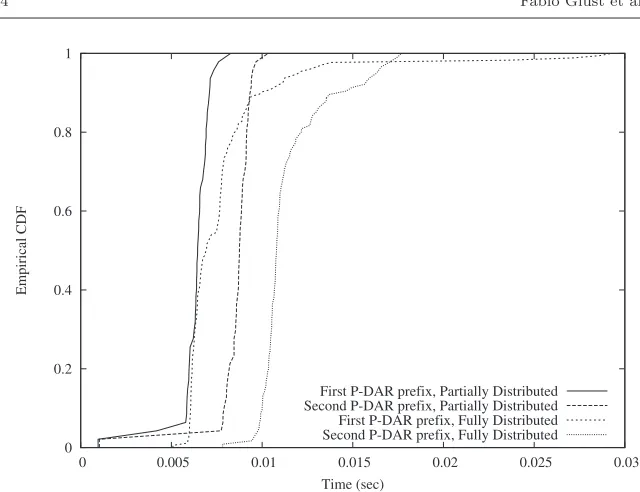
Fig. 11 Comparison of the CDF of the handover latency with different number of active prefixes.
implementation simplifications have an impact on the obtained performance results.
In order to compare and understand the performance of the partially and the fully distributed solutions, we measured the handover latency for both approaches (with one and two active prefixes). Fig. 11 shows the empirical cumulative distribution function (eCDF) of measured results. Each of the ex-periments consists in the MN connecting to DAR1, next moving to DAR2and DAR3, and finally disconnecting. By doing this, after the first handover, only one prefix (the one anchored at DAR1) is updated, whereas after the second movement, two prefixes are updated (the ones anchored at DAR1and DAR2). To better understand the contribution of the IP mobility operations to the overall handover latency, we added timers in the code to extract the times-tamps when the PBU, PBA, RS and RA messages are sent and received. With this information we can deriveTbinding as characterized in Section 5.2. Note that not analyzingTL2ho,Tauth,TDAD andTM Din our experiments does not impact the comparison of the partially and fully distributed approaches, as all those values are identical in the analyzed situations.