R E S E A R C H
Open Access
Remote control system of disaster response
robot with passive sub-crawlers considering
falling down avoidance
Soichiro Suzuki
1, Satoshi Hasegawa
2and Masayuki Okugawa
3*Abstract
This paper describes a remote control system for a crawler-type mobile robot with passive sub-crawlers. This system has a great advantage because it utilizes an essential compliant mechanism that allows the angle of the sub-crawlers to be adapted to the shape of the road surface. Its operation is extremely simple, and it is only necessary to control the movement direction and driving speed in comparison with the case of controlling active sub-crawlers. However, a robot with passive sub-crawlers cannot recover from a situation in which it is stuck. The operator must select a traversable route for unknown rough terrain using only the information obtained from camera images and some sensor data from the robot. In this study, a remote control system for a crawler robot with passive sub-crawlers was developed based on a warning system. This system evaluates the currently selected route by calculating the stabilization for the robot when falling down in the roll and pitch directions. Experimental results obtained using a prototype crawler robot with passive sub-crawlers demonstrated the effectiveness of the proposed system.
Keywords: Crawler; Passivity; Predictive; Falling down avoidance; Remote control; Route selection; Stability margin
Background
Remote-controlled mobile robots are useful for search-ing around and inside buildsearch-ings that have collapsed in a disaster. In a disaster area, to avoid the risk of sec-ondary disasters, it is preferable to immediately deploy remote-controlled mobile robots instead of waiting for first responders such as firefighters. Disaster response robots should have high mobility on rough terrain. The movement mechanism of a crawler-type robot with sub-crawlers has been applied to many disaster response robots in order to realize high mobility [1]. However, its use complicates robot operation because the opera-tor must actively control each sub-crawler by estimating the attitude or state of the robot based on camera images and sensor information. Therefore, because of the multi-ple degrees of freedom involved, operators must be well trained to achieve high mobility by using remote control. A semi-autonomous control system for crawler robots has
*Correspondence: [email protected]
3Aichi Institute of Technology, 1247 Yachigusa, Yakusa, Toyota, 4700369 Aichi, Japan
Full list of author information is available at the end of the article
been studied to realize both high mobility and simple operation [2,3]. This study focused on a crawler robot with passive sub-crawlers to realize simple operation with mul-tiple degrees of freedom. Passive sub-crawlers can adapt to unknown rough terrain. We developed a crawler-type mobile robot for conducting search operations around a disaster area. Passive sub-crawlers called “Scotta I” were adopted for this robot. In a crawler robot with passive sub-crawlers, it is only necessary to control the move-ment direction and driving speed, unlike in the case of controlling active sub-crawlers. However, posture control is impossible in passive sub-crawlers because the opera-tor cannot actively control each sub-crawler, and a robot with passive sub-crawlers cannot recover from a situation in which it is stuck. A robot with passive sub-crawlers is extremely simple, but it is essential for the operator to possess considerable skill when selecting a route. The operator must select a traversable route for unknown rough terrain using only the information obtained from camera images and sensor data from the robot.
In this paper, we propose a warning system, not a semi-autonomous control system, for a remote-controlled dis-aster response robot, because the operator should have
the authority to make the final decision in order to realize flexible operation at all times. By evaluating the stabil-ity margin, a remote control system for a crawler robot with passive sub-crawlers is proposed that adopts the warning system with a dynamic threshold. The current route selected by the operator is evaluated by calculat-ing the stabilization for the robot while fallcalculat-ing down in the roll and pitch directions. An operator can prevent the robot from falling down based on the sound and signals from the warning system when the evaluation value for the stability margin is less than the threshold. The pro-posed system will be able to prompt the operator to select another route. A method of compensating for the disad-vantages of a crawler robot with passive sub-crawlers will be proposed in this paper. This paper describes a method
for evaluating the potential for falling down by using a predictive falling down margin time based on the normal-ized energy (NE) stability margin. The results of exper-iments demonstrated the effectiveness of the proposed system.
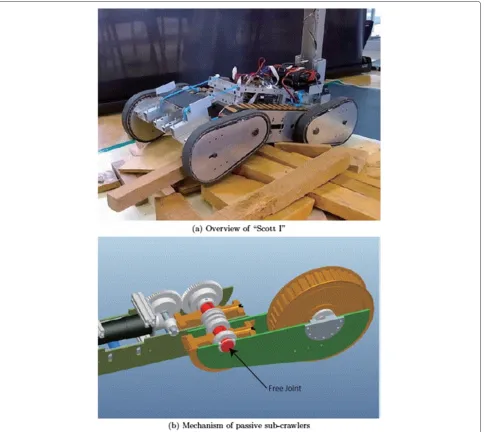
Disaster response robot “Scott I”
Figure 1(a) shows an overview of the “Scott I” crawler-type mobile robot. Table 1 lists the robot’s specifications. The driving mechanism of the main crawler includes a drive motor and four sub-crawlers (front×2, rear× 2). Figure 1(b) shows a cross-sectional view of the sub-crawlers’ joint part. Each rotary joint of the sub-crawlers can rotate freely and has passivity. The rotation of a sub-crawler’s belt is transmitted from the main crawler.
Table 1 Specifications of Scott 1
Dim. of the robot [mm] Length×Width×Height
Max. 720×390×145
Min. 370×290×100
Timing pulley dia. [mm]
Large 145
Small 100
Belt width [mm]
Main crawler 50.8
Sub-crawlers 25.4
Weight [kg] 20.0
Max. speed [m/s] 0.35
However, the rotations of the right and left sub-crawlers are not independent.
The operation of a robot with active sub-crawlers is complicated because the operator should control not only the main body but also each sub-crawler. A semi-autonomous control system has been considered to over-come the disadvantage of a crawler-type robot with active sub-crawlers. We do not intend to deny the approach for a semi-autonomous control system. A crawler-type robot with passive sub-crawlers is known to have a great advan-tage because it has an essential compliant mechanism that allows the angle of the sub-crawlers to be adapted to the shape of the road surface [4,5]. The operator only needs to control the movement direction and driving speed. The effectiveness of passive sub-crawlers has been con-firmed by simulations and experiments, and the mobil-ity performance of Scott I was appreciated in RoboCup Japan Open Rescue Robot League 2013 and in the eval-uation field at IRS (International Rescue System Institute in Japan). On the other hand, it is necessary to restrict
the rotational angle of a sub-crawler to avoid a singular configuration when moving over a step, and numerical simulations and experiments show that the restricting angle differs with the step height and road shape. Scott I can change the restriction angle of the sub-crawlers by adjusting the length of the belt and stopper member. However, the restriction angle cannot be changed in real time. Therefore, a subject for future work will be a con-trol method to set a suitable restriction angle based on the step height and road-surface shape.
Principle of traversing on simple step for crawler-type robot with passive sub-crawlers
The principle of traversing a simple step for a crawler-type robot with passive sub-crawlers is described. If the diameters of the pulleys for the sub-crawlers are the same, only a forward driving force is generated. Therefore, no upward power is generated, and the center of gravity of the main body of the robot cannot be moved above the obstacle. On the other hand, after the tip of a sub-crawler makes contact with an obstacle, a vertical force acts, and the sub-crawler is rotated upward by the larger pulley of the contact side. The robot will begin to traverse the step by increasing the driving force to a value greater than the weight of the robot itself.
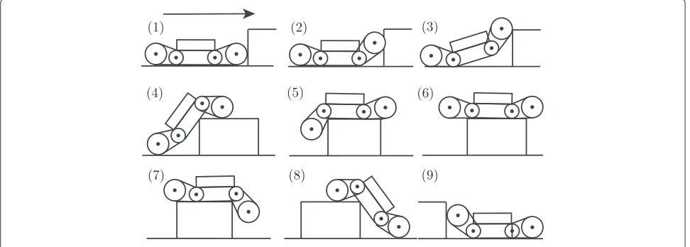
Figure 2 shows the sequence when a crawler-type robot with passive sub-crawlers traverses a simple step. This sequence was confirmed by the results of simulations and experiments. The traversing sequence for a simple step is explained as follows. The height of a simple step is defined as greater than the radius of the large forward timing pul-ley, and less than the height of the center of gravity on the perpendicular robot.
1. The force acts vertically.
2. The front sub-crawlers press against the surface of the step and rotate upward.
3. The attitude angle of the main crawler increases. 4. The height of the center of gravity is higher than the
objective step and moves forward from the rotational center of the rear sub-crawlers’ joint.
5. The front sub-crawlers and main body move over the step.
6. The entire robot moves over the step. 7. The front sub-crawlers rotate downward. 8. The front sub-crawlers make contact with the
ground.
9. The rear sub-crawlers make contact with the ground, and the robot finishes moving over the step.
Warning system
Necessity of warning system
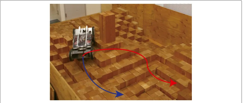
As mentioned in the previous section, the operation is simple because a crawler robot with passive sub-crawlers can traverse rough terrain using only instructions regard-ing the movregard-ing direction and drivregard-ing speed as long as sufficient ground pressure is applied, and the rotational angle of the sub-crawlers is appropriately restricted. How-ever, posture control using the sub-crawlers is impossible because the operator cannot control the sub-crawlers individually. Therefore, the operator predicts the traver-sal of an obstacle or the state of the robot given sufficient ground pressure, and they must select an appropriate route using only the camera image and sensor informa-tion obtained from the robot (Figure 3). One problem lies in the fact that the operator must master skills for route selection in order to prevent the robot from falling down.
This paper proposes a warning system to assist the oper-ator with route selection. This system can indicate and evaluate the stability margin for the potential of falling
down by using the angle information for the robot’s body in the pitch and roll directions. To prevent the robot from falling down, the proposed system can provide a warn-ing to the operator when the stability index is below the threshold value by quantitatively evaluating the current route. A flowchart for the proposed system is shown in Figure 4. We evaluate the stability of the robot on the basis of the NE stability margin. This system has the ability to support operations in a narrow space without depending on images from an overlooking camera.
Derivation of normalization energy stability margin The NE stability margin En(t) is a stability index for a robot. It is based on the difference between the maximum heighthmaxand the current heighth(t)[mm] for the cen-ter of gravity when the robot body rotates around the pitch and roll axes.
En(t)=hmax−h(t) (1)
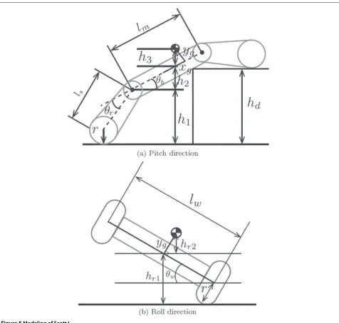
In this study, hp(t) andhr(t)were defined as the h(t) values in the pitch and the roll directions, respectively. The robot’s center of gravity h(t) was calculated using the body angles in the pitch θb(t) [rad], and roll θw(t) [rad] directions, along with the relative angle of the sub-crawlers θf(t) to the main crawler. θb(t) was measured using a gyroscope, and θf(t) and θr(t) were measured using a potentiometer. Figure 5(a) shows the modeling of the robot and parameters for the pitch direction.
The length of the main crawler islm[mm], length of the sub-crawlers isls[mm], and radius of the pulley isr[mm]. In the initial state,yg[mm] is the vertical coordinate of the center of gravity from the road surface, andxg[mm] is the horizontal coordinate of the center of gravity from the center of the main body. When moving up stairs,hp1(t)
Figure 4Flowchart for warning system.
is expressed by equation (2). When moving down stairs, hp1(t)is expressed by equation (3).
hp1(t) = lssin(θr(t)+θb(t))+r (2) hp1(t) = lssin
θf(t)+θb(t)+r (3)
hp2(t) =
1
2lm+xg−ygtanθb(t)
sinθb(t) (4)
hp3(t) = yg
cosθb(t) (5)
hp(t) = hp1(t)+hp2(t)+hp3(t) (6) hp(t) = hp1(t)+hp2(t)+hp3(t) (7)
The coordinate of the center of gravity for the roll direc-tion is calculated by measuring the body angle in the roll direction (−π/2 < θw(t) < π/2) using the gyro-scope. Figure 5(b) shows the modeling of the robot and parameters in the roll direction.
hr1(t) = 1
2lwsin|θw(t)| +rcosθw(t) (8) hr2(t) = ygcosθw(t) (9) hr(t) = hr1(t)+hr2(t) (10)
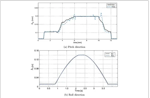
Verification of estimated center of gravity
The validity of equations (6), (7), and (10) is confirmed by comparing the estimated value with the experimental one. The estimated value is effective in the range of expression (11) provided that the crawler is always in contact with the ground. Where,hdis defined it as the height of the step.
r<hd<xg+ 1
2lm+ls+r (11)
The range of the rotational angle for the sub-crawlers is limited to values between−40 deg and 30 deg in order to avoid the singular configuration of the front sub-crawlers.
It is not necessary to consider the influence of the front sub-crawlers, because the rotation range is narrow. Figure 6 shows the experimental and estimated values. Figure 6(a) and (b) shows that the estimated value agrees very well with the experimental one. The error observed from 4—6 sec in Figure 6(a) occurs because the sub-crawlers do not make contact with the ground. The error observed from 9—12 sec is the spike noise included in the sensor data for the angular angular velocity measured using a gyroscope when the robot moves over the step. An experiment in the roll direction was performed for a robot traversing a slope on one side of the crawler. The experi-mental and estimated values are shown in Figure 6(b). The roll direction of the center of gravity was exactly estimated for the sub-crawlers that were always in contact with the ground. The experimental values of the center of gravity were calculated using the coordinate obtained from image processing. The marker was attached in order to trace the center of gravity for the robot.
Examination of threshold for warning system
The timing of a warning is generated using the threshold of the NE stability margin En(t). It is possible to pre-vent the robot from falling down if the operator takes appropriate action in response to the warning.
In this paper, a predictive falling down margin timeTm is adopted to warn the operator that the robot will fall down.Tm is calculated by using the time derivative for the NE stability marginEn(t), as shown in Figure 7. When t= ¯t, a gradientα(¯t)is defined asdEn(¯t)/dt. The equation of a tangential line for En(t) at t = ¯t is derived using equation (12).
Figure 5Modeling of Scott I.
Tm is defined as a time before En = 0 from ¯t using equation (13).
Tm= − En(t¯)
α(¯t) (13)
Tr is defined as the reaction time of the operator and Teis defined as the reflection time for the operator’s con-trol. The timing to give the warning should be decided in consideration ofTm and the reaction time of the opera-tor Tr. The reaction time is estimated asTr = 0.4 sec based on reference [6]. The reflection time is estimated to beTe = 0.1 sec in consideration of the time delay for system execution. The threshold time is determined to be Tm = 0.5 sec in this paper. In addition, a notice will be
displayed 0.4 sec before the warning. The attention time is assigned while 0.5<Tm<1.0.
Method for operation support
Figure 6Comparison of estimated and experimental values.
be presented as a warning by voice and a signal because of the risk of the robot falling down.
In the case of a robot with active sub-crawlers, the oper-ator must appropriately control each sub-crawler’s angle in every sequence. A robot may fall down if the opera-tor lacks adequate skill even if it is a traversable step. In addition, the difference between the traveling sequences of active and passive sub-crawlers lies in the manner in which the rear crawlers are utilized. Passive sub-crawlers can only rotate using gravity; consequently, no
Figure 7Image of predictive falling down margin time.
downward power to lift the robot body is generated. Adopting passive sub-crawlers has many advantages. It can reduce the number of high-torque motors, reduce the robot weight, and save energy. The relationship between the traversing condition and the sub-crawlers’ restricting angle is reported in another paper.
Methods
Experimental operation verification using Scott I
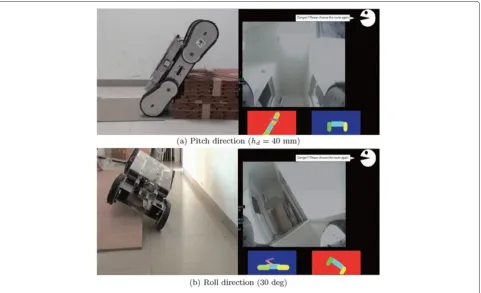
We confirmed the process of the proposed system using an experimental verification under a real environment. In the experiment, we observed the progress of the operator response to the warning provided by the proposed sys-tem. In the experimental condition for the pitch direction, the target obstacle was a simple step (height: 0.4 m, depth: 0.3 m, width: 0.8 m) with an impossible height that was to be traversed. In the experimental condition for the roll direction, the target obstacle was a slope with a 30 deg angle of inclination. The robot traversed this slope only with the left side of the crawler, as shown in Figure 9(b). The operator screen and the posture of Scott I during this experiment are shown in Figure 9.
Figure 8Display method for operation support information.
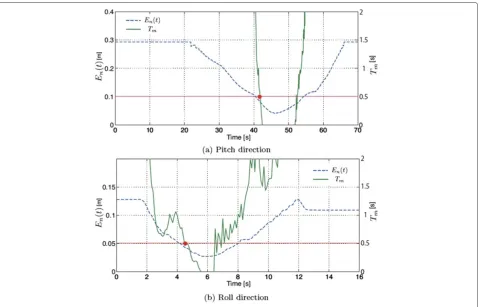
Figure 10. The experimental results demonstrate the effec-tiveness of the proposed system, as shown in Figure 10. We confirmed that the operator could react appropriately to prevent the robot from falling down within approx-imately 5.0 sec of the warning. However, the robot fell down when the operator did not react at the warning because a strict threshold was assumed. In addition, we
could not confirm the effectiveness of the attention time because of the short setting time. We would like to con-sider these in our future work.
Experimental evaluation and consideration
The experimentation for the evaluation of the proposed system was performed with 10 test subjects. We chose
Figure 10Experimental operation verification of proposed system.
expert operators for half the subjects and beginner oper-ators for the rest. On the other hand, the beginner operators were defined as inexperienced operators. The objective of the experiment was to evaluate the reaction of each subject in the operating process for traversing a sim-ple step or slope. The experiment was performed using three cases:
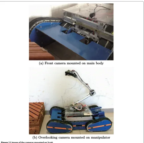
Case 1 Using only the images from the front camera (shown in Figure 11(a))
Case 2 Using only the images from the overlooking cam-era mounted on the manipulator (shown in Figure 11(b))
Case 3 Using the proposed system.
Each subject performed the operation nine times for these experimental cases.
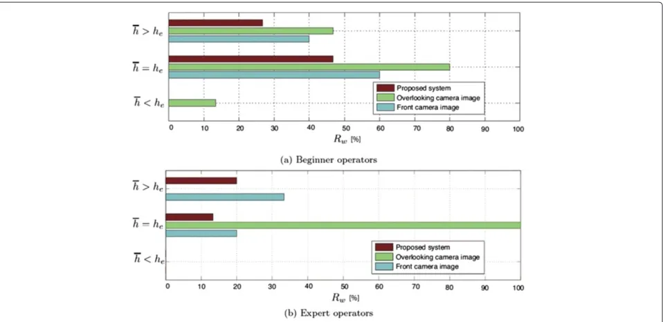
Equation (14) defines the height of the objective travers-ing step h, where he [m] is the maximum height of the step that the robot can traverse and εh is the adjustable height of the step. The step height was clas-sified three conditions (h = 180, 230, 280 mm), and we chose randomly it for each test subjects. Each step height condition was chosen to become the same number of experiments.
h=he+εh (14)
In the case where the step to be traversed had an untraversable height (h > he)we defined a misjudgment as the situation in which the robot fell down even though the subject could traverse the objective step and the robot could continue to move forward. We also defined a mis-judgment as the situation in which the subject operated the robot backward upon understanding that the step to be traversed had an untraversable height.
The experimental results were evaluated by the mis-judgment rateRwbased on equation (15), whereExis the number of times the experiment was conducted andMjis the number of misjudgments.
Rw= Mj Ex
(15)
However, the same number of experiments was performed for each step height condition. The experi-ments were only performed in the pitch direction at a controllable constant speed (350 mm/sec) for a sampling period of 0.1 sec.
Figure 11Image of the cameras mounted on Scott.
each step height show in Table 2. The results and dis-cussion are given below based on observing the perfor-mances of the operators and discussing these after the experimentation.
Results and discussion
First, the results for the beginners are shown in Figure 12(a). In the case of h > he, the appropriate judgment is “move backward” because of the untra-versable step height. When using only the images from the front camera (Case 1) or those from the overlooking cam-era (Case 2), the value ofRwwas high. From these results,
we confirmed that when only using camera images, it is difficult for operators to respond appropriately to prevent the robot from falling down. The obstacle moves out of the camera frame whenever a robot traverses the step because the attitude angle of the robot increases. Therefore, the judgment depends on the experience of the operator. In the case ofh > he, we frequently observed the tendency of the cautious judgment to “move backward”. As a result, the misjudgment rate in the case of h > he was smaller than the case ofh=he.
Figure 12Experimental results for misjudgment rate.
untraversable step heighth > he. The operators could appropriately control the robot to prevent it from falling down.
Second, in the case ofh=he, the value ofRwwas high under all of the experimental conditions. The “move back-ward” choice was considered a misjudgment because of the traversable step height. The reasons for Case 1 and Case 2 were similar in the case ofh > he. Hence, rash operations and falling down were frequently observed. The reasons for Case 3 was different. The judgment of almost all of the subjects was to “move backward,” par-ticularly when using the proposed system. By adopting the proposed warning system, the cautious judgments increased, but rash judgments decreased. The proposed system attached importance to the capability to avoid falling down. When observing the experiments forh=he, it seemed that some subjects were confused because the driving speed of the robot had to be controlled in the case
Table 2 Standard deviations for misjudgment rate
Step height Beginner Expert
Case 1 38.9 29.8
h>he Case 2 26.6 0
Case 3 24.9 26.7
Case 1 24.9 26.7
h=he Case 2 26.6 0
Case 3 45.2 26.7
Case 1 0 0
h<he Case 2 26.7 0
Case 3 0 0
of the limit of the traversable steph= he. This was con-firmed by the standard deviation results (h= he, Case 3, Beginner) as listed in Table 2. The driving speed will need be considered in future work.
Finally, for the traversable step heighth ≤ he, because the operators only had to select the simple command “Forward” in all cases, the robot was able to traverse the step. The misjudgments of the subjects were almost always “move backward” when using only images from the overlooking camera (Case 2). This result shows that increasing the information to the operator will result in more cautious judgments.
Figure 12(b) shows the experimental results for the misjudgment rate of the expert operators. This rate was smaller than that for the beginners overall. Furthermore, the value of the standard deviation is also small in the case of an expert. We confirmed that the expert opera-tors could perform an appropriate judgments. In the case ofh > he, when using only a images from the overlook-ing camera (Case 2), all of the subjects avoided falloverlook-ing down. The subjects chose the more cautious judgment based on the experience gained in the previous experi-ments because Case 2 was the last to be performed. In the case of the warning system, we observed that a relatively inexperienced operator let the robot fall down.
movement speed, we confirmed that the high success rate was achieved by repeated stops and starts.
Conclusion
This paper describes a warning system for a crawler robot with passive sub-crawlers. The proposed support system for the operator could display an evaluation index for the selected route based on the NE stability margin of the robot. Experiments were performed by using Scott I to verify the proposed system. We compared the misjudg-ment rates between the beginner and expert operators under different experimental conditions. The experimen-tal results demonstrated the effectiveness of the proposed system in all cases. We confirmed that the proposed sys-tem was able to stimulate a cautious judgment. Based on the experimental results, we found that it was nec-essary to provide suitable support based on the skill of the operator. For expert operators, it would be best for the system to provide only assistance. On the other hand, because of their lack of skill, beginner operators cannot react quickly enough to prevent the robot from falling down. Hence, in order to support a beginner operator, we think that it would be best for the system to interrupt their actions, such as through a speed-controlled system. In future work, an experiment will be performed in a real environment by using an improved system to evalu-ate the effectiveness of the proposed method for expert or beginner operators.
Endnote
aAbbreviation for “Scouting Crawler Robot
Technology”.
Competing interests
The authors declare that they have no competing interests.
Authors’ contributions
SH devised the basic concept of the overall system, technically constructed the system and drafted the manuscript. SS carried out the experiments and helped to draft the manuscript. MO suggested the constitution of the article and helped with the editing of the manuscript. All authors read and approved the final manuscript.
Acknowledgements
The authors would like to thank Sanritz Automation Co. Ltd. for the development of the computer, “TPIP”. This work was supported by a JSPS KAKENHI Grant-in-Aid for Scientific Research (B), No. 23310116.
Author details
1Graduate School of Engineering, Aichi Institute of Technology, 1247 Yachigusa, Yakusa, Toyota, 4700369 Aichi, Japan.2Daiichi System Engineering, 4F Green Bldg, 1-16-20 Nishiki Naka Nagoya, 460003 Aichi, Japan.3Aichi Institute of Technology, 1247 Yachigusa, Yakusa, Toyota, 4700369 Aichi, Japan.
Received: 15 January 2014 Accepted: 23 May 2014
References
1. Koyanagi E (2010) Rescue robot with active sub crawlers. J Robot Soc Japan 28(2):147–150
2. Ohno K, Morimura S, Tadokoro S, Koyanagi E, Yoshida T (2007) Semi-autonomous control system of rescue crawler robot having flippers for getting over unknown-steps. In: Proceedings of the IEEE/RSJ international conference on intelligent robots and systems 2007. pp 3012–3018 3. Okada Y, Nagatani K, Yoshida K, Yoshida T, Koyanagi E (2010) Shared
autonomy system for tracked vehicles to traverse rough terrain based on continuous three-dimensional terrain scanning. In: Proceedings of the IEEE/RSJ international conference on intelligent robots and systems 2010. pp 357–362
4. Yuuki K, Ikarashi T, Oogane K (2010) Validity of passivity mechanism with rescue robots. In: Proceedings of annual conference of robotics society of Japan 2010. pp 3–14
5. Kang S, Lee W, Kim M, Shin K (2005) Robhaz-rescue: Rough-terrain negotiable teleoperated mobile robot for rescue mission. In: Proceedings of the IEEE/RSJ international conference on intelligent robots and systems 2010. pp 105–110
6. Teichner WH, Krebs MJ (1974) Laws of visual choice reaction time. Psychol Rev 81(1):75–98
doi:10.1186/s40648-014-0020-9
Cite this article as:Suzukiet al.:Remote control system of disaster response robot with passive sub-crawlers considering falling down avoidance.ROBOMECH Journal20141:20.
Submit your manuscript to a
journal and benefi t from:
7Convenient online submission 7 Rigorous peer review
7Immediate publication on acceptance 7 Open access: articles freely available online 7High visibility within the fi eld
7 Retaining the copyright to your article