Towards the design of monolithic decoupled XYZ
compliant parallel mechanisms for
multi-function applications
G. Hao
Department of Electrical and Electronic Engineering, School of Engineering, University College Cork, Cork, Ireland
Correspondence to: G. Hao ([email protected])
Received: 30 January 2013 – Accepted: 19 April 2013 – Published: 15 August 2013
Abstract. This paper deals with the monolithic decoupled XYZ compliant parallel mechanisms (CPMs) for multi-function applications, which can be fabricated monolithically without assembly and has the capability of kinetostatic decoupling. At first, the conceptual design of monolithic decoupled XYZ CPMs is presented using identical spatial compliant multi-beam modules based on a decoupled 3-PPPR parallel kinematic mecha-nism. Three types of applications: motion/positioning stages, force/acceleration sensors and energy harvesting devices are described in principle. The kinetostatic and dynamic modelling is then conducted to capture the displacements of any stage under loads acting at any stage and the natural frequency with the comparisons with FEA results. Finally, performance characteristics analysis for motion stage applications is detailed investigated to show how the change of the geometrical parameters can affect the performance characteristics, which pro-vides initial optimal estimations. Results show that the smaller thickness of beams and larger dimension of cubic stages can improve the performance characteristics excluding natural frequency under allowable con-ditions. In order to improve the natural frequency characteristic, a monolithic decoupled configuration that is achieved through employing more beams in the spatial modules or reducing the mass of each cubic stage mass can be adopted. In addition, an isotropic variation with different motion range along each axis and same pay-load in each leg is proposed. The redundant design for monolithic fabrication is introduced in this paper, which can overcome the drawback of monolithic fabrication that the failed compliant beam is difficult to replace, and extend the CPM’s life.
1 Introduction
Compliant parallel mechanisms (CPMs) transmit mo-tion/loads by deformation of their compliant links (namely jointless), and belong to a class of parallel-type mechanisms. They aim to utilize the material compliance/flexibility in-stead of only analyzing/suppressing the negative flexibility effect like those initial works in the area of kinematics of mechanisms with elasticity (Howell, 2001; Hao, 2011). This revolutionary change leads to many potential merits such as reduced part count (monolithic), zero backlashes, no need for lubrication, reduced wear, high precision and compact con-figuration in comparison with the rigid-body counterparts. CPMs with multiple DoF (degrees of freedom) have drawn
more attentions from academia and industries due to their ex-tensive applications such as motion/positioning stages (Aw-tar and Slocum, 2007; Dong et al., 2007; Hao and Kong, 2012a, b), acceleration/force sensors (Gao and Zhang, 2010; Hansen et al., 2007; Cappelleri et al., 2010) and energy har-vesting devices (Rupp et al., 2009; Ando et al., 2010).
al., 2007; Hao and Kong, 2012b; Gao and Zhang, 2010), which leads to some issues such as assembly error, increased number of parts, reduced stiffness (by about 30 % by bolted joints), and increased cost (Hao and Kong, 2012b). Over recent years, 3-D printing technology has been developed rapidly. Various base/substrate materials, such as engineering plastics, ceramics and metal, can be used for fabrication for a variety of applications. But the emerging 3-D printing tech-nology may lead to limited or undesired performance char-acteristics of material due to no traditional heat treatment ap-plied and inherent layer-by-layer fabrication. This shortcom-ing has been proved by testshortcom-ing our initial prototype, made of engineering plastic, obtained using a 3-D printer. Therefore, better manufacturing approaches/strategies for spatial multi-DoF CPMs are potentially needed. Averting the manufactur-ing issue on spatial CPMs, one can design a type of spatial multi-DoF CPMs that are possible to be fabricated mono-lithically using the above planar manufacturing technologies without bringing any assembly issues.
In this paper, we will mainly deal with the XYZ CPMs with (kinetostatically) decoupled configuration. Kinetostatic decoupling means that one primary output translational dis-placement is only affected by the actuation force along the same direction, which describes the relationship between the input force and output motion. This decoupling (not abso-lute) is also called the output-decoupling/minimal cross-axis coupling in CPMs. Kinetostatic coupling may lead to com-plicated motion control, which is the sufficient condition of kinematic decoupling. A number of literatures have reported the design of decoupled XYZ CPMs for motion/positioning stage and sensing applications (Hao and Kong, 2009, 2012b; Gao and Zhang, 2010; Li and Xu, 2011; Pham et al., 2006; Yue et al., 2010; Tang et al., 2006) using kinematics de-sign methods (Hao, 2011). Here, each of the three kinematic legs/chains, which are coupled in parallel, is individually a serial-parallel hybrid arrangement. But none of them have showed the possibility for monolithic fabrication. Also, these designs have their own limitations such small motion range (Li and Xu, 2011; Pham et al., 2006; Yue et al., 2010), bulky and complex configuration (due to the serial-parallel hybrid arrangement) (Li and Xu, 2011; Pham et al., 2006; Hao and Kong, 2009; Tang et al., 2006), and poor out-of-plane stiff -ness of the PP plane in each leg (Li and Xu, 2011; Pham et al., 2006; Hao and Kong, 2009; Yue et al., 2010; Tang et al., 2006). Recently, Awtar et al. (2013) proposed a novel XYZ parallel kinematic flexure mechanism with geometri-cally decoupled DoF using identical flexure plates, which has a more compact and simpler construction and has the possi-bility to be fabricated monolithically. However, this design suffers from complicated modelling, bad out-of-plane stiff -ness and big lost motion, especially its three actuation di-rections are skew and cannot intersect at the center of the primary motion stage so that its applications are limited in low payload, and/or low speed. Hao and Kong (2012b)
re-ported a decoupled XYZ CPM composed of identical spatial modules, but still has the challenging issue on fabrication.
This work builds on the above advances on decou-pled XYZ CPMs towards a monolithic configuration (also compact and simple) for manufacturing purpose. It also stresses the potential extensive applications in multi-axis motion/positioning stages, multi-axis sensors (accelera-tion/force), and energy harvesting devices using the present monolithic decoupled XYZ CPMs.
This paper is organized as follows. Section 2 proposes the conceptual design of monolithic decoupled XYZ CPMs for three-type applications: motion/positioning stages, acceler-ation/force sensors, and energy harvesting devices at first. Then the analytical kinetostatic and dynamic modelling is undertaken in Sect. 3. In Sect. 4, the performance character-istics analysis to reflect the change of performance charac-teristics with that of the geometrical parameters is investi-gated. Section 5 discusses the thermal stability. Conclusions are drawn in Sect. 6.
2 Conceptual design of monolithic decoupled XYZ CPMs for multi-function applications
2.1 Monolithic decoupled XYZ CPMs
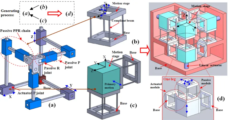
A decoupled XYZ CPM for the motion/positioning stage can be generated using a design approach proposed in the ref-erences (Hao, 2011; Hao and Kong, 2012b). This design is demonstrated in Fig. 1, which is based on a decoupled XYZ parallel kinematic mechanism (PKM) whose three planes as-sociated with the passive PPR kinematic chains are orthogo-nal. It is obtained by replacing the actuated P joint and the passive PPR chain in each leg of the 3-PPPR XYZ PKM (Fig. 1a) with the compliant P joint in Fig. 1c and a com-pliant PPR joint in Fig. 1b, respectively, and making appro-priate arrangement for the identical building blocks (spatial four-beam modules).
Figure 1.The generating process of a decoupled XYZ CPM: (a) A decoupled 3-PPPR XYZ PKM (Hao, 2011; Hao and Kong, 2012b) with three planes associated with the passive PPR kinematic chains orthogonal; (b) A compliant planar-motion PPR joint (Hao, 2011; Hao et al., 2011; Hao and Kong, 2013): spatial four-beam module that is composed four identical symmetrical square wire beams spaced around a circle uniformly; (c) A compliant P joint (Hao, 2011; Hao and Kong, 2012b): two spatial four-beam modules connected in parallel, two planes associated two PPR joints of which are orthogonal; (d) A decoupled XYZ CPM using identical spatial four-beam modules.
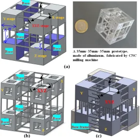
Three different monolithic forms are shown in Fig. 2a, b and c, respectively. As mentioned earlier, the monolithic de-coupled XYZ CPM (for instance, Fig. 2a) has mainly three types of applications: motion/positioning stages, accelera-tion/force sensors, and energy harvesting devices, which is detailed as follows.
2.1.1 High-precision motion/positioning stages
For the applications as high-precision motion/positioning stages, the proposed monolithic decoupled XYZ CPM (Fig. 2a) can be actuated by three linear Voice Coil (VC) actuators for large motion range or by three PZT actuators for small motion range as shown in Fig. 1d. In addition three optical linear encoders (input sensing) and three capacitive measuring systems (output sensing) are required.
2.1.2 Acceleration/force sensors
The presented monolithic decoupled XYZ CPM (Fig. 2a) can be used as the 3-axis acceleration/force sensor without using linear actuators. For the use as the force sensor, any external force exerted at the XYZ-stage along each axis can be sensed by measuring the displacements of the X-, Y- and Z- stages along the X-, Y-, and Z-axes, respectively, by piezoresistors or other types of sensors. When used as the acceleration sen-sor, the XYZ-, X-, Y- and Z-stages are served as the inertial mass of the sensor. If there is a acceleration along certain
resultant direction, the components of the resultant iniertial force along the X-, Y-, and Z-axes will result from the con-tribution of the combined mass of the XYZ- and X-stages, that of the and Y-stages, and that of the of the XYZ-and Z-stages, respectively. Then by sensing displacements of the X-, Y- and Z-stages along the X-, Y-, and Z-axes, respec-tively, one can obtain the inertial force along each axis and then work out the acceleration along each axis.
2.1.3 Energy harvesting devices
Coupling with magnets and coils, an example 3-axis en-ergy harvesting device (Fig. 3) can be obtained based on the monolithic decoupled XYZ CPM (Fig. 2a). It harvests energy in three axes through the well-known eletromagnetic induc-tion. If there is an external exitation along a certain axis, the inertial mass (including the magnet) coupled with the com-pliant members (spring) along this axis will produce a vabri-ation to make the magnet to go through the coil, and then magnetic flux changes with time, which induces the electric-ity production for harvesting.
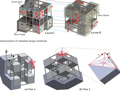
2.2 Redundant design for monolithic fabrication
Figure 2.Monolithic decoupled XYZ CPMs: (a) a monolithic decoupled XYZ CPM with three geometrical parameters; (b) a monolithic decoupled XYZ CPM with improved natural frequency via reducing the cubic stage mass; and (c) a monolithic decoupled XYZ CPM with improved natural frequency via increasing the beam number (i.e. stiffness enhanced) (all configurations have same motion range).
Figure 3.Energy harvesting devices: (a) Energy harvesting device based on a monolithic decoupled XYZ CPM; (b) Perspective view of FEA resutls in deformation; (c) Top view of FEA results in deformation.
present monolithic decoupled XYZ CPM in this paper is a re-dundant design with three rere-dundant spatial four-beam mod-ules inactive (or four cubic stages fixed), and therefore the redundant building blocks (or fixed cubic stages) can swap the functions with certain failure’s mobile building blocks (or mobile cubic stages) to extend the system life.
In our design, each of three passive spatial four-beam mod-ules undergoes two translations, and is prone to fail com-pared to other spatial modules to produce only one transla-tion. If either of the three passive spatial four-beam modules fails, the base frame originally connecting the four fixed
cu-bic stages can be moved to connect with the four originally mobile cubic stages in their initially undeformed configura-tion. Such a way, the life of the XYZ CPM is retrieved. A more clear illustration is shown in Fig. 4.
Figure 4.Demonstration of redundant design (rendered).
Figure 5.A variation for the monolithic decoupled XYZ CPM.
same payload (isotropic) (Kong and Gosselin, 2002; Werner et al., 2010), a variation can be made from the present mono-lithic decoupled XYZ CPM as shown in Fig. 5.
This variation has the decoupling property with regard to the original coordinate system X1Y1Z1. But in the new
coor-dinate system XYZ, the motion is not decoupled. The motion relationships between the two coordinate systems will be fol-lowed in the subsequent section.
3 Modelling of the monolithic decoupled XYZ CPM
In order to analyzing the performance characteristics of the monolithic decoupled XYZ CPM (Fig. 2a), it is essential to carry out the kinetostatic modelling and dynamic modelling.
3.1 Kinetostatic modelling
References (Hao, 2011; Hao and Kong, 2012b) have given the detailed analytical modelling derivation for an XYZ CPM using identical spatial double four-beam modules, therefore, in this paper, we will directly use the associated linear equa-tions from these references with differenct geometrical pa-rameters substitution. The purpose for linear kinetostatic
modelling is to approximately estimate the displacements of the centers of the XYZ-, X-, Y-, and Z-stages under the action of loads at the centers of those stages to suit different appli-cations. Here, the normalization-based strategy (Hao et al., 2011; Hao and Kong, 2013) is also adopted to represent loads and displacements using the corresponding lower-case let-ters, which refers to that all translational displacements and length parameters are normalized by the beam actual length L, forces by EI/L2, and moments by EI/L. Here, E and I
de-notes the Young’s modulus and the second moment of the area of a symmetrical cross-section, respectively.
The compliance matrix for the CPM system (Fig. 2a) with regard to the center of the XYZ-stage in the global coordi-nate system XYZ, i.e. the loads and displacements are both defined at the center, is obtained as
Ccpm=K−cpm1 =(Rleg1Kleg2Rleg1−1 +Kleg2+Rleg3Kleg2R−leg31 )
−1 (1)
where Ccpmand Kcpmare the compliance and stiffness
matri-ces of the CPM system, respectively; Kleg2is the stiffness
transformation so that Kleg1=Rleg1Kleg2R−leg11 , and Kleg3=
Rleg3Kleg2R−leg31 ; Rleg1and Rleg3are the rotation
transforma-tion matrices for Legs 1 and 3, respectively, which are given as
Rleg1= "
RZ(−π/2)3×3 03×3
03×3 RZ(−π/2)3×3 #
×
"
RY(−π/2)3×3 03×3
03×3 RY(−π/2)3×3 #
,
and
Rleg3= "
RY(π/2)3×3 03×3
03×3 RY(π/2)3×3 #
×
"
RZ(π/2)3×3 03×3
03×3 RZ(π/2)3×3 #
.
The stiffness matrix of Leg 2 can be represented as
Kleg2=[Jm3(RppCmR−pp1)J T
m3+JpCpJTp]
−1 (2)
where Cmis the compliance matrix of the spatial four-beam
module (compliant PPR joint, Fig. 1b) in Leg 2 with regard to the center of the bottom-plane of its own motion stage in its own local coordinate system; Cpis the compliance matrix
of the compliant P joint (Fig. 1c) in Leg 2 with regard to the Y-stage center in the global coordinate system; Jm3and Jpare
the position transformation matrices, and Rpp is the rotation
transformation matrix, which are detailed below:
Jm3=
I3×3
0 0 −w/2
0 0 0
w/2 0 0
03×3 I3×3
,
Jp=
I3×3
0 0 −1−w
0 0 0
1+w 0 0
03×3 I3×3
, and
Rpp= "
RZ(π/2)3×3 03×3
03×3 RZ(π/2)3×3 #
.
The compliance matrix of the compliant P joint is further represented as
Cp={(Jm1CmJTm1)
−1+[J
m2(RmCmR−m1)J T m2]
−1}−1 (3)
where Jm1and Jm2 are the position transformation matrices,
and Rmis the rotation transformation matrix, which are
ex-pressed below:
Jm1=
I3×3
0 0 0
0 0 w/2 0 −w/2 0
03×3 I3×3
,
Jm2=
I3×3
0 w/2 0
−w/2 0 0
0 0 0
03×3 I3×3
, and
Rm= "
RY(π/2)3×3 03×3
03×3 RY(π/2)3×3 #
×
"
RZ(π)3×3 03×3
03×3 RZ(π)3×3 #
.
The compliance matrix of the spatial four-beam module is further derived as
Cm= 4 X
i=0
DTiKDi
−1 (4) where
Di=
I3×3
0 z0 i −y
0 i −z0
i 0 x 0 i y0 i −x 0 i 0
03×3 I3×3
, and K=
d 0 0 0 0 0
0 12 0 0 0 −6
0 0 12 0 6 0
0 0 0 1/(1+v) 0 0
0 0 6 0 4 0
0 −6 0 0 0 4
.
Here, x01=0, y01=(w−t)/2, and z10=(w−t)/2; x02=0, y02= (w−t)/2, and z02=−(w−t)/2; x03=0, y03=−(w−t)/2, and z03=−(w−t)/2; x04=0, y40 =−(w−t)/2, and z04=(w−t)/2. d=12/(t)2 for square cross-section with normalized
thick-ness t. v is the Poisson’s ratio of the material.
Based on the above modelling results, the relationships be-tween the displacements at the center of the XYZ-stage and the loads acting at both the actuation points and the centers of the XYZ-, X-, Y-, and Z-stages are derived as
F=KcpmXs−Kleg1Rleg1(JpCpJTp)R
−1 leg1J
T pa1Fax
−Kleg2(JpCpJTp)J T
pa2Fay−Kleg3Rleg3(JpCpJTp)R
−1 leg3J
T pa3Faz,
i.e.
Xs=Ccpm
h
F+Kleg1Rleg1(JpCpJTp)R
−1 leg1J
T
pa1Fax+Kleg2
×(JpCpJTp)J T
pa2Fay+Kleg3Rleg3(JpCpJTp)R
−1 leg3J
T pa3Faz
i
(5)
where F=[ fx,fy,fz,mx,my,mz]T and Xs=[xs,ys,zs, θsx,θsy,θsz]T which are the load-vector and
the X-stage along the X-, Y-, and Z-axes, respectively; Jpai (i=1, 2, 3) in Eq. (5) is the position transformation
matrix for loads in each leg, which is shown below
Jpai=
I3×3
0 z0 i −y
0 i −z0
i 0 x 0 i y0 i −x 0 i 0
03×3 I3×3
.
Where, x0
1=−(1+w), y
0
1=0, and z
0
1=0; x
0
2=0, y
0
2=−(1+w),
and z0
2=0; x
0
3=0, y
0
3=0, and z
0
3=−(1+w).
We can then obtain the displacements at the centers of the X-, Y-, and Z-stages as
Xax=Rleg1CpR−leg11 J T p1
h
Kleg1
Xs−Rleg1(JpCpJTp)
×R−leg11 JTpa1Fax
+JTpa1Fax i
,
Xay=CpJTp2[Kleg2(Xs−JpCpJTpJTpa2Fay)+JTpa2Fay],
Xaz=Rleg3CpR−leg31 h
Kleg3
Xs−Rleg3
×(JpCpJTp)R
−1 leg3J
T pa3Faz
+JTpa3Faz i
(6)
where Xax=[xax,yax,zax,θax−x,θax−y,θax−z]T,
Xay=[xay,yay,zay,θay−x,θay−y,θay−z]T,and
Xaz=[xaz,yaz,zaz,θaz−x,θaz−y,θaz−z]T, which denote the
dis-placement vectors at the centers of the X-, Y- and Z-stages. As an example for explaining the displacement symbols, xay,
yay, and zaydenote the translational displacements of the
Y-stage center along the X-, Y- and Z-axes, respectively; Jpi
(i=1, 2, 3) is the position transformation matrix for loads in each leg as
Jpi=
I3×3
0 z0i −y0i −z0
i 0 x 0 i y0 i −x 0 i 0
03×3 I3×3
.
Here, x0
1=(1+w), y
0
1=0, and z
0
1=0; x
0
2=0, y
0
2=(1+w), and
z0
2=0; x
0
3=0, y
0
3=0, and z
0
3=(1+w).
optimization.
3.2 Dynamic modelling
Accurate dynamic equations can be obtained from the clas-sical Lagrange equation building on the above kinetostatic modelling results. However, we only give approximate esti-matations of the natural frequencies of the monolithic decou-pled XYZ CPM using simplified stiffness models.
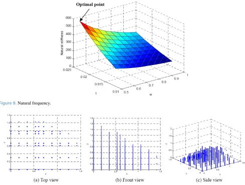
The actual primary translational stiffness along each axis can be simplied as
K=1612EI
L3 =16
ET4
L3 . (7)
Then the equal first, second or third-order natural frequency is derived as
fI= p
K/(M)/(2π) (8)
where M is the actual motion mass along each axis only con-sidering two stages neglecting the compliant beams’ mass.
Given that all stages are identical, M is double of mass of each (cubic) stage, which is equal to 2ρW3with a density of ρ. So Eq. (8) is rewritten as
fI= q
8ET4/(ρW3L3)/(2π)= q
8Et4/(ρw3L2)/(2π). (9)
3.3 Resutls analysis
Let the material be a standard aluminum alloy AL 6061-T651 with Young’s Modules E=69 Gpa and Poisson’s ra-tio v=0.33. Also, we define the geometrical parameters as: L=20 mm (beam length), W=20 mm (cubic stage’s side-length), T=1 mm (beam thickness) (i.e. a system dimen-sion of 60 mm×60 mm×60 mm) for the initial performance analysis.
xs ys zs θsx θsy θsz
=Ca−s
fax−x fay−y faz−z fax−x fay−y faz−z =
0.005341 −0.00006975 −0.00006975 0 0 0
−0.00006975 0.005341 −0.00006975 0 0 0
−0.00006975 −0.00006975 0.005341 0 0 0
0 0 0 0 −0.0001112 0.0001112
0 0 0 0.0001112 0 −0.0001112
0 0 0 −0.0001112 0.0001112 0
fax−x fay−y faz−z fax−x fay−y faz−z . (10a) xay yay zay
θay−x
θay−y
θay−z
=Ca−a
fax−x fay−y faz−z fax−x fay−y faz−z
=
1.280×10⁻⁵ 3.1193×10⁻⁷ −1.7446×10⁻⁷ 0 0 0 −0.00006961 0.005367 −0.00006961 0 0 0 −1.7446×10⁻⁷ 3.1193×10⁻⁷ 1.280×10⁻⁵ 0 0 0
0 0 0 0 −0.00008392 0.00008371 0 0 0 3.8288×10⁻⁷ 0 −3.8288×10⁻⁷ 0 0 0 −0.00008371 0.00008392 0
fax−x fay−y faz−z fax−x fay−y faz−z
. (10b)
The above equations can clearly show the performance characteristics for any three-axis loading. For example, under a single force, the ratio of magnitude of the parasitic rotation about the X- (or Z-axis) to the primary translation along the Y-axis can be obtained based on Eq. (10a) as
Ca−s(4,5)
Ca−s(2,2) =
0.0001112
0.005341 =2.08 %. (11)
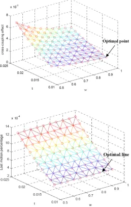
The cross-axis coupling effect, for example the effect of fay−y
upon xs, is then determined using Eq. (10a) by
Ca−s(1,2)
Ca−s(2,2) =
0.00006975
0.005341 =1.31 %. (12)
Moreover, the lost motion percentage under a single loading can be written using the results in Eqs. (10a) and (10b) as
Ca−a(2,2)−Ca−s(2,2)
Ca−s(2,2)
=0.005367−0.005341
0.005341 =0.49 %. (13)
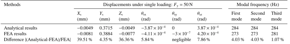
Equation (10a) shows that the force applied along an axis cannot produce the parasitic rotation about this axis. And two equal forces applied along two out of three axes, respectively, cannot cause the parasitic rotation about the third axis either. In addition, simple comparisons, including kinetostatic and dynamic, between the analytical results and the FEA results (using Solidworks) are given in the Table 1, which shows good agreements in primary motion displacement, parasitic rotational angles, and modal frequency. There is rel-atively large difference only in cross-axis coupling motion, which may result from the error of the linear analytical mod-eling (or that of the FEA results), but have reasonable esti-mation in the changing trends.
4 Performance characteristics analysis
In this section, performance characteristics analysis for the monolithic decouple XYZ CPM as the motion stage (Fig. 2a) is conducted to see how the geometrical parameters’ change can affect the performance characteristics and which perfor-mance characteristic is most sensitive to a geometrical pa-rameter. This analysis will provide an initial optimization.
Figures 6, 7, and 8 illustrate the performance characteris-tics, defined in Eqs. (11), (12) and (13), against the normal-ized beam thickness, t, and the side-length, w, of the (cubic) stage under the conditions of specified material and beam length. Some key findings are summarized as follows.
– The parasitic rotation (Fig. 6) is influenced by both w and t, and increases with the increase of t and decreases with the increase of w. It is more sensitive to t compared with w. The smaller w is, the larger the effect of t on the parasitic rotation is. Similarly, the larger t is, the larger the effect of w on the parasitic rotation is.
– The cross-coupling (Fig. 7) is also affected by both w and t, and increases with the increase of t or with the decrease of w. It is also more sensitive to t in compari-son with w. The smaller w is, the larger the effect of t on the cross-coupling is, and the larger t is, the larger the effect of w on the cross-coupling is.
– The lost motion (Fig. 8) is insensitive to w, and only is dominated by t. the smaller t, the smaller the lost mo-tion is.
In addition, under the specified material, the translational motion range (same motion range along each axis) is only affected by the normalized beam thickness, t, and insensitive to the side-length, w, of the stage. The decrease of t can im-prove the motion range.
We can conclude from the above results that desired performance characteristics (large-range motion, minimized parasitic rotation, minimized cross-coupling and minimal lost motion) can be achieved by employing smaller t and ap-propriately larger w under the allowable conditions such as the minimum fabrication thickness, the overall system size, and stiffness/frequency requirements.
FEA results −0.0081 0.3884 −0.0077 −4.11×10⁻⁴ −3×10⁻⁷ 4.20×10⁻⁴ 273 273 281 Difference|(Analytical-FEA)/FEA| 39.51 % 4.35 % 36.36 % 5.84 % negligible 7.86 % 4.03 % 4.03 % 1.07 %
Figure 6.Parasitic rotation effect.
more beams in each spatial module as indicated in Fig. 2c, and/or reducing the mass of the cubic stages as indicated in Fig. 2b.
The motion of the variation (Fig. 5) in the coordinate sys-tem XYZ can be further determined by the following equa-tions
Z=(X21z+Y1z2 +Z21z)0.5
subject to X1z=Y1z=Z1z with all positive values;
Y=(X21y+Y1y2 +Z21y)0.5
subject to Y1y=Z1y with both negtive values and
Y1y
=0.5X1y;
X=(Y21x+Z21x)0.5
subject to |Y1x|=|Z1x|
with a positive Z1x and a negtive Y1x (14)
where X, Y, and Z is the positive resultant motion in the co-ordinate system XYZ. X1z, Y1z, and Z1zare the motion along
the X1-, Y1-, and Z1-axes, respectively, in the coordinate
sys-tem X1Y1Z1 contributing to Z. Y1y, and Z1y are the motion
along the Y1-, and Z1-axes, respectively, in the coordinate
system X1Y1Z1 contributing to Y. X1x, Y1x, and Z1xare the
motion along the X1-, Y1-, and Z1-axes, respectively, in the
coordinate system X1Y1Z1contributing to X.
Let the motion range along each positive axis in the coor-dinate system X1Y1Z1beδ, the following constraint
condi-tions should be met:
0<=X1=X1y+X1z<=δ;
−δ <=Y1=Y1x+Y1y+Y1z<=δ;
−δ <=Z1=Z1x+Z1y+Z1z<=δ. (15)
From the above resutls, it is directly obtained that the max-imal single-axis motion along the positive X-axis is 20.5δ,
the maximal single-axis motion along the positive Y-axis is 1.50.5δ, and the maximal single-axis motion along the
posi-tive Z-axis is 30.5δ.
The workspace for this variation in Octant I of the coordi-nate system XYZ can be obtained using numerical approach based on the above results (Eqs. 14 and 15), and is shown in Fig. 10. Note that the number of points in Fig. 10 depends on the set-up step size in the numerical approach.
5 Discussions
Figure 7.Cross-coupling effect.
Figure 8.Lost motion percentage.
The monolithic design proposed in this paper is an over-constraint design in both the individual spatial multi-beam modules and the three identical legs. Although the problems of over-constraint are largely mitigated by the fact that the mechanism is monolithic and requires no assembly, there are still problems with its over-constraint. For instance, when VC actuators are used, the temperature will vary over the mech-anism producing stress building up that can be problematic for precision performance. Moreover, when the mechanism heats up, the stage will drift as the design is not fully sym-metric and thus not considered thermally stable.
6 Conclusions
This paper has presented and modelled a monolithic de-coupled XYZ CPM (Fig. 2a) for multi-function applica-tions: motion/positioning stages, acceleration/force sensors,
and energy harvesting devices. The proposed monolithic de-coupled XYZ CPM uses only identical spatial multi-beam modules as the building blocks involving three geometrical parameters and can be fabricated by the planar manufactur-ing technologies (such as EDM) without assembly as the 2-D compliant mechanisms.
In addition, the monolithic decoupled XYZ CPM with im-proved natural frequency (Fig. 2b and c) and the variation with different motion range in each axis and same payload in each leg (Fig. 5) have been proposed. Redundant design for monolithic fabrication has been discussed in this paper, which can be used to extend the CPM’s life.
Figure 9.Natural frequency.
Figure 10.Workspace of the variation in Octant I of the coordinate system XYZ.
It is noted that the proposed design may promote the fab-rication using the carbon nanotubes or carbon fibers, which may lead to novel compliant mechanisms used in the emerg-ing MEMS or nano-electro-mechanical-systems (NEMS). Experiment verification, nonlinear modelling, fatigue analy-sis, and optimization deserve further investigation in the near future.
Acknowledgements. The author would like to sincerely appreci-ate the reviewers’ valuable comments for improving the quality of this paper. Special thanks goes to Tim Power and Michael O’Shea for their excellent technical knowledge in fabricating the prototype in UCC.
Edited by: Y. Li
Reviewed by: H. Tang and one anonymous referee
References
Ando, B., Baglio, S., Trigona, C., Dumas, N., Latorre, L., and Nouet, P.: Nonlinear mechanism in MEMS devices for energy
harvesting applications, J. Micromech. Microeng., 20, 125020, doi:10.1088/0960-1317/20/12/125020, 2010.
Awtar, S.: Analysis and Synthesis of Planar Kinematic XY Mecha-nisms, Sc.D. thesis, Massachusetts Institute of Technology, Cam-bridge, MA, 2004.
Awtar, S. and Slocum, A. H.: Constraint-Based Design of Parallel Kinematic XY Flexure Mechanisms, J. Mech. Design, 129, 816– 830, 2007.
Awtar, S., Ustick, J., and Sen, S.: An XYZ Parallel Kinematic Flexure Mechanism with Geometrically Decoupled Degrees of Freedom, Journal of Mechanisms and Robotics, 5, 015001, doi:10.1115/1.4007768, 2013.
Cappelleri, D., Krishnan, G., Kim, C., Kumar, and V., Kota, S.: Toward the Design of a Decoupled, Two-Dimensional, Vision-Based uN Force Sensor, Journal of Mechanisms and Robotics, 2, 021010, doi:10.1115/1.4001093, 2010.
Dong, W., Sun, L. N., and Du, Z. J.: Design of a Precision Compli-ant Parallel Positioner Driven by Dual Piezoelectric Actuators, Sensor. Actuat. A-Phys., 135, 250–256, 2007.
418–427, 2010.
Hansen, B. J., Carron, C. J., Jensen, B. D., Hawkins, A. R., and Schultz, S. M.: Plastic Latching Accelerometer Based on Bistable Compliant Mechanisms, Smart Mater. Struct., 16, 1967– 1972, 2007.
Hao, G.: Creative Design and Modelling of Large-Range Trans-lational Compliant Parallel Manipulators, Ph.D. thesis, Heriot-Watt University, Edinburgh, UK, 2011.
Hao, G. and Kong, X.: A 3-DOF Translational Compliant Parallel Manipulator Based on Flexure Motion, in: Proceedings of 2009 ASME International Design Engineering Technical Conferences & Computers and Information in Engineering Conference, San Diego, CA, USA, 30 August–2 September, DETC2009-86075, 2009.
Hao, G. and Kong, X.: Novel XY Compliant Parallel Manipulators for Large Translation with Enhanced Out-of-Plane Stiffness, J. Mech. Design, 134, 061009, doi:10.1115/1.4006653, 2012a. Hao, G. and Kong, X.: Design and Modelling of a Large-Range
Modular XYZ Compliant Parallel Manipulators Using Identi-cal Spatial Modules, Journal of Mechanisms and Robotics, 4, 021009, doi:10.1115/1.4006188, 2012b.
Hao, G. and Kong, X.: A Normalization-Based Approach to the Mobility Analysis of Spatial Compliant Multi-Beam Modules, Mech. Mach. Theory, 59, 1–19, 2013.
Hao, G., Kong, X., and Reuben, R. L.: A Nonlinear Analysis of Spa-tial Compliant Parallel Modules: Multi-beam Modules, Mech.
Mach. Theory, 46, 680–706, 2011.
Howell, L. L.: Compliant Mechanisms, Wiley, New York, 2001. Kong, X. W. and Gosselin, C. M.: Kinematics and Singularity
Anal-ysis of a Novel Type of 3-CRR 3-DOF Translational Parallel Ma-nipulator, I. J. Robot. Res., 21, 791–798, 2002.
Li, Y. and Xu, Q.: A Totally Decoupled Piezo-Driven XYZ Flexure Parallel Micropositioning Stage for Micro/Nanomanipulation, IEEE T. Autom. Sci. Eng., 8, 265–279, 2011.
Pham, H.-H., Yeh, H. C., and Chen, I.-M.: Micromanipulation Sys-tem Design Based on Selective Actuation Mechanisms, Int. J. Robot. Res., 25, 171–185, 2006.
Rupp, C. J., Evgrafov, A., Maute K., and Dunn, M. L.: Design of Piezoelectric Energy Harvesting Systems: A Topology Optimiza-tion Approach Based on Multilayer Plates and Shells, J. Intel. Mat. Syst. Str., 20, 1923–1939, 2009.
Tang, X., Chen, I.-M., and Li, Q.: Design and Nonlinear Modeling of a Large-Displacement XYZ Flexure Parallel Mechanism with Decoupled Kinematics Structure, Rev. Sci. Instrum., 77, 115101, doi:10.1063/1.2364132, 2006.
Werner, C., Rosielle, P. C. J. N., and Steinbuch, M.: Design of a Long Stroke Translation Stage for AFM, International Journal Machine Tools and Manufacture, 50, 183–190, 2010.