183 | P a g e
DROOP CONTROL STRATEGIES OF DC MICROGRID
Sayli E. Mhankale
Student Member, IEEE, Department of Electrical Engineering, Rajarambapu Institute of Technology, Islampur-415414, India. sayliemhankale@gmail.com
A. R. Thorat
Department of Electrical Engineering, Rajarambapu Institute of Technology, Islampur-415414, India. arun.thorat@ritindia.edu
Abstract—As a consequence of the increasing demand for electricity and environmental issues, the generation of electrical energy from renewable energy sources has improved in recent times. The renewable energy sources are connected with power grids all around the world. The increasing part of distributed energy resources in the current power system, has formed new chances and tests. Microgrid is the primary stage of future smart grid. This paper generally investigates the switching structures of microgrid reliant upon conventional power system droop control. Microgrid droop switch schemes are deliberated in specifics for improving the understanding in microgrid control. This paper analyses droop control strategy of DC microgrid. As DC microgrid goes on developing, the control strategies of DC microgrid draw more and more attention. An ample survey of variety of issues associated with droop control strategies of DC microgrid is presented in this paper.
Keywords—DC microgrid, Control strategy, Frequency control, Power flow, Droop control.
I. INTRODUCTION
The power industries worldwide has noticed a huge change in utilization of power because of increased use of distributed energy resources, accompanied by beginning of recent development in power electronics with cost reduction. Now days the power system is more intricate and more organized. It produces electricity by combustion of fossil fuels like diesel, coal, nuclear fuel, natural gas, etc. This generates injurious particles and gases which spoils environment also reduces life.
Distributed energy resources are comprised of different distributed generation technologies like wind energy, wave / tidal power, Genset (range of fuels), fuel cell, solar thermal / solar photovoltaic, geo-thermal, micro-hydro, energy storing structures (hydrogen fuel cell, flywheels, batteries, ultra-capacitors, compressed air etc.), combined heat and power (CHP) that are connected with sharing grids near to load request [1]. While changing from traditional AC distribution to DC microgrid the trends like telecommunication, military operations, data centers, transportation, etc. are involved [2]. The output of solar PV, energy storages and most of the loads are of DC type. So DC microgrid is preferred over AC microgrid [3]. The joining of clean and renewable energy system can be achieved by microgrid with multi-energy
generations (MGMEG) and storing like photovoltaic production, fuel cells, ultra-capacitors, wind generation, micro turbines, battery banks etc. The quality and reliability of power because of devolution of source can be increased by the request organization and extreme effectiveness of existing energy [4-6].
Microgrid is bunch of micro sources, storage devices, distributed loads (non-critical and critical), CHP, electric vehicles, controllable and flexible interface close to customers. Microgrid can work in both grid connected mode or islanded (or isolated) mode. Microgrid provides reliable, green and safe electric power, reduces harmful emission, develop network quality. It has DC, AC and hybrid DC-AC configuration [7-17]. The line figure of usual microgrid have been shown in Fig. 1.
Fig. 1. Line figure of a classic microgrid
184 | P a g e
i. Automatic generation control / Capacity frequency switch/MW frequency switch /automatic load frequency control
ii. MVAr- Voltage switch / excitation switch.
In this paper, section II gives control scheme of conservative power system. Section III gives literature review of control scheme of microgrid and the section IV gives conclusion.
II. CONTROL SCHEME OF CONVENTIONAL POWER SYSTEMS
The speed governing system is provided to all the generators in conventional power system. The generators frequency regulation characteristics are as indicated in Fig. 2.
Fig. 2. Frequency droop characteristic of generator
With the rise in load demand frequency falling, the governor increases input to the prime mover to increase the speed. And when the decrease in load demand frequency falling, the governor decreases input to the prime mover to decrease the speed. This is done to settle the specified range i.e. ± 3%. The closed loop control is used for control purpose. Types of frequency control is explained below:
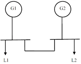
Fig. 3. Two generators connected over tie line
The two generating stations G1 and G2 are coupled over tie line as shown in Fig. 3. The loads L1 and L2 are joined to two generators separately. The kinds of frequency control are:
i. Flat frequency regulation: When any one of the generator G1 or G2 supplies the increased load demand.
ii. Parallel frequency regulation: When both the generators equally share the increased load. iii. Flat tie line: When the increase in load of a
specific zone is lit by the generator of the same area.
A. Primary load frequency control (PLFC)
PLFC is composed of speed governing scheme, load, spinning apparatuses (generators and turbines) and power system [20]. Block illustration exemplary of PLFC control scheme is as shown in Fig. 4.
Fig. 4. Model of PLFC control strategy
Here,
∆𝑃𝐶 is variation of position location
𝐺𝐻 is transfer function of governor
𝐺𝑇 is transfer function of turbine
∆𝑃𝐿 is variation of capacity
𝐺𝑃 transfer function of power system
ΔF variation of frequency
R is droop value or regulation in speed governor
For usual circumstances, the variation of position location ∆𝑃𝐶= 0, then,
𝑉
𝑙𝑑=
𝐾𝑉𝑑𝑐
2 𝐶𝑠
2+𝐾𝐾𝑝𝑉𝑑𝑐 2 𝑆+𝐾𝐾𝑖
𝑉𝑑𝑐 2 𝐿𝐶𝑠3+𝐾𝑉𝑑𝑐
2 𝐶𝑠2+(1+𝐾𝐾𝑝 𝑉𝑑𝑐
2 )𝑠+𝐾𝐾𝑖 𝑉𝑑𝑐
2
𝑉
𝑙𝑑∗−
𝐿𝑠2
𝐿𝐶𝑠3+𝐾𝑉𝑑𝑐
2 𝐶𝑠2+(1+𝐾𝐾𝑝 𝑉𝑑𝑐
2 )𝑠+𝐾𝐾𝑖 𝑉𝑑𝑐
2
(𝐼
𝑙𝑑+ 𝐼
𝑓)
(1)
So, 𝑉𝑙𝑑= 𝐺(𝑠)
𝑉
𝑙𝑑∗ − 𝑍(𝑠)(𝐼𝑙𝑑+ 𝐼𝑓)(2)
185 | P a g e miscalculation to nil and for controlling of changing
aspects in scheme [21].
B. Secondary load frequency control (SLFC)
Recommended control scheme requirements:
Control loop essentially take adequate amount of steadiness.
Resulting a stage capacity variation, stationary miscalculation must be nil.
Fundamental of frequency miscalculation should be reduced.
Fig. 5. Model of SPLFC control strategy
The various categories of controllers are integral controller, proportional controller, differential controller, proportional –derivative (PD) controller, proportional-integral-derivative (PID) controller and proportional-integral (PI) controller. The integral type controller is used for dropping the static error to zero. Fig. 5 shows the block figure exemplary of SPLFC switch scheme, here 𝐾𝑖 is an increase. Choice of cost is quite
difficult because this selects energetic performance of the system.
C. Tertiary load control (TLC)
TLC is also called as economic load dispatch. In this, the cost of Ki and β is selected in a way so that switch accomplishment is ideal. The multi-area system requires this control. A typical power system is distributed among sub-systems in that generators work in comprehensible manner and adjacent to individual.
III. CONTROL STRATEGY OF MICROGRID
The renewable energy sources are the favorable replacement to fossil fuel. They endeavor many benefits over conventional power sources. The only disadvantage is that the resultant power is intermittent also stochastic in nature. To overcome this disadvantage and to improve the superiority of power resource to make the system more effective, the renewable distributed generators are used. An autonomous microgrid is designed by establishing energy storage system (ESS) [22]. Microgrids can work in both grid connected mode and islanded mode of operation. Islanded mode can be switched depending upon energy price, power quality, error in key grid and steadiness apprehension. The
system frequency and voltage is imposed by microgrid in grid connected mode. The droop control of frequency and voltage is an important method for power division. In microgrids, for coordinated voltage and frequency regulation and to ensure power sharing, the most popular droop control method is used [23-25].
The droop control strategy optimally synchronizes distributed generation units’ droop characteristics. During inadequate generation periods, it controls the shading of microgrid power demand. To upkeep the IMG process for a big time frame, the PEVs charging / discharging control is done by droop control strategy. [26] presented a hierarchical microgrid controlling scheme for integrating the key control stages required for microgrid action by using task sharing and dispatch strategy based on a transformative game theory as a coordinated algorithm. [27] proposed a graded switch to understand best destabilizer imbursement for improved power quality. For making the scattered generators likewise part the compensation exertions and for realizing the distorted reimbursement for serious bus, the primary and secondary controllers are put on. [28], proposed a decentralized control strategy that permits storing stage of individual microgrid for going about a standard cost by supportive allotment of power among microgrids. [29], presented the novel robust switching scheme required on behalf of an islanded microgrid in the existence of capacity unmodeled changing aspects.
The microgrid involves parallel assembly of several DER arrangements and a limited capacity. [30], presented a heuristic methodology for dynamic request side organization in the off grid arrangements for a group of definite requests. [31], proposed an incorporated reimbursement context by means of mutual load ailment in limited controller, to pay compensation the voltage fall and capacity allotment miscalculations. The voltage eccentricity is counterbalanced through a relative regulator when capacity sharing is remunerated over a relative important regulator. [32], refers to the dynamic power distribution of several distributed generators (DGs) among a microgrid.
IV. SIMULATIONWORK
A. The Design of Droop Controller
186 | P a g e characteristics of reactive power vs. voltage. This
gives the new stable system state.
The droop characteristic curve is shown in figure 6.
Fig. 6. Droop Characteristic
The nominal frequency and nominal amplitude of inverters output voltage are given by the following formulae:
𝑓
𝑛= 𝑓
0− 𝑚
𝑛𝑝
𝑛𝑉
𝑛= 𝑉
0− 𝑛
𝑛𝑄
𝑛 If the output of some source has more active power, then reduce its frequency so as to reduce active power output.
If the output of some source has less active power, then increase its frequency so as to increase active power output.
If the output of some source has more reactive power, then reduce its voltage so as to reduce reactive power output.
If the output of some source has less reactive power, then increase its voltage so as to increase reactive power output.
B. The parameter design of power control loop
The formula for droop ratio is given as:
𝑚𝑛=
𝑃𝑚𝑎𝑥− 𝑃𝑛
𝑓𝑛− 𝑓𝑚𝑖𝑛
𝑛𝑛= 𝑄𝑚𝑎𝑥
𝑉0−𝑉𝑚𝑖𝑛 (2)
In this formula,
𝑃𝑚𝑎𝑥 is maximum real power output
𝑃𝑛 is active power at nominal frequency
𝑓𝑛 is nominal frequency
𝑓𝑚𝑖𝑛 is minimum allowable frequency for which
DG gives maximum output power
𝑄𝑚𝑎𝑥 is maximum reactive power
𝑉0 is the amplitude of output voltage when
reactive power of DG is zero
𝑉𝑚𝑖𝑛 is the minimum allowable amplitude of
voltage
The designed power controller is shown in figure 2.
Fig. 7. Power Controller
The necessary conditions of active and reactive power output for the power controller are:
1. 0 ≤ P ≤ 𝑃𝑚𝑎𝑥
2. −𝑄𝑚𝑎𝑥 ≤ Q ≤ 𝑄𝑚𝑎𝑥
Assume that, when microgrid is operating in islanded mode, the microsource can provide sufficient active power for the connected loads. Then the designed parameter should change the amplitude of voltage less than±5% and change in frequency less than ±1%.
C. The parameter design of voltage and current double loop
L
𝑑𝐼𝑖𝑛𝑣 𝑑𝑡=
1
2
m
𝑉
𝑑𝑐-
𝑉
𝑙𝑑(3)
In the formula (3), m indicates the signal of controllable sinusoidal modulation
m = m sin(wt-Ø-i
2𝜋3
) (4)
i = 0, 1, 2;
𝐼
𝑖𝑛𝑣is the output current vector of the inverter;𝑉𝑙𝑑 is the load voltage vector.
So the differential equation of the filter capacitor is given as below:
C
𝑑𝑉𝑙𝑑𝑑𝑡
=
𝐼
𝑖𝑛𝑣– (
𝐼
𝑙𝑑+
𝐼
𝑓)
In the formula (4), I_ld is the load current vector; I_f is the current vector which flow to the power grid.
By considering formula (3) and (4), the voltage and current double loop controller is designed as shown in figure (4). The stabilization of load voltage is achieved by voltage loop. To make the steady-state precision zero, the PI controller is used.
𝐾𝑝 is scale factor
𝐾𝑖 is integral factor
K is proportional constant
For enhancing the system dynamic response, the current loop is used.
187 | P a g e
as the input,
𝑉
𝑙𝑑as
the output, transfer function of the voltage loop can be calculated:𝑉𝑙𝑑 =
𝐾𝑉𝑑𝑐 2 𝐶𝑠
2+𝐾𝐾
𝑝𝑉𝑑𝑐2 𝑆+𝐾𝐾𝑖𝑉𝑑𝑐2
𝐿𝐶𝑠3+𝐾𝑉𝑑𝑐
2 𝐶𝑠2+(1+𝐾𝐾𝑝 𝑉𝑑𝑐
2 )𝑠+𝐾𝐾𝑖 𝑉𝑑𝑐
2
𝑉𝑙𝑑∗
-𝐿𝑠2𝐿𝐶𝑠3+𝐾𝑉𝑑𝑐
2 𝐶𝑠2+(1+𝐾𝐾𝑝 𝑉𝑑𝑐
2 )𝑠+𝐾𝐾𝑖 𝑉𝑑𝑐
2
(𝐼𝑙𝑑+ 𝐼𝑓) (5)
So,
𝑉𝑙𝑑 = 𝐺(𝑠)𝑉𝑙𝑑∗ −𝑍(𝑠)(𝐼𝑙𝑑+ 𝐼𝑓) (6)
In the formula (6), G(s) is the proportion gain transfer function and Z(s) is the equivalent output impedance of the inverter.
From the expression of Z(s) we can calculate output impedance of the inverter. It is closely related to the parameter of the controller.
Z(s)
=
𝐿𝑠2𝐿𝐶𝑠3+𝐾𝑉𝑑𝑐
2 𝐶𝑠2+(1+𝐾𝐾𝑝
𝑉𝑑𝑐
2 )𝑠+𝐾𝐾𝑖
𝑉𝑑𝑐 2
(7)
For the current loop controller, K = 5
L = 0.6mH, C=1500μ F, V = 800V
For the voltage loop controller, 𝐾𝑖 = 100.
Fig. 8. Voltage and current double-loop controller When𝐾𝑝 <1, then the output impedance of the inverter
is more resistive.
When 𝐾𝑝 > 1, then the output impedance of the inverter
is more inductive.
The width of the frequency band of the inductive impedance is directly proportional to 𝐾𝑝. 𝐾𝑝should be
chosen such that the inductive frequency band of the output impedance is not too broad because high frequency output impedance can suppress harmonics because of its resistive character.
The resistivity of inverters output impedance is directly proportional to the integral parameter 𝐾𝑖. The
output impedance is inductive when 𝐾𝑖=1. The output
impedance is completely resistive when 𝐾𝑖= 5000. 𝐾𝑖
should be chosen such that the inductive frequency band of the output impedance is not too broad. To make sure that the output impedance is inductive, define 𝐾𝑝 as 10.
V.OUTPUT OF MATLABSIMULATION
Fig. 9. PCC Voltage
Fig. 10. PCC Current
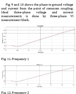
Fig. 9 and 10 shows the phase to ground voltage and current from the point of commom coupling. Ideal three-phase voltage and current measurements is done by three-phase VI measurement block.
Fig. 11. Frequency 1
Fig. 12. Frequency 2
188 | P a g e the PLL regulator is scaled according to the input
signals magnitude.
Fig. 13. Active power 1
Fig. 14. Active Power 2
Fig. 13 and 14 shows the outputs of two power (mask) blocks. Power mask computes the active and reactive powers of a voltage-current pair at fundamental frequency. For the first cycle of simulation, the outputs are held constant to the powers computed for the Voltage initial input and current initial input parameters.
VI. DRAWBACKS OF DROOP CONTROL STRATEGY
It makes decisions based on local information only. This increases the reliability of the system. The system is easy to expand. It cannot make changes to control strategies depending on different working conditions because there is no information sharing between terminals. There will be a drop in voltage and power quality of the system in decentralized control. Also, the load sharing is the major problem.
Droop control is a type of decentralized control strategy. It makes decisions based upon local information. In droop control, micro-generators and energy storage systems share the loads according to characteristic lines (V-I characteristic lines), as shown in Fig. 3.6. It can detect the local voltage and the working points moving on the characteristic lines when the required power is changed. However, due to the resistance of the transmission lines, the load cannot be shared accurately as expected. The voltage drops a lot that result in the poor power quality.
Fig. 15. Droop characteristic line of DC microgrid
VII. SOLUTION OF THESE PROBLEMS
In the proposed control strategy, the bus voltage is divided into several levels. The control strategy makes different decisions in different levels for arranging the power flow in better way. The grid connected mode differs from isolated mode by the presence of utility grid. In grid connected mode, the utility grid takes part in the power balance. The DC micro grid can switch among several modes according to the differences of voltage level as shown in Fig. In different modes, different control strategies are applied to micro generators and energy storage systems to keep the voltage fluctuation deviation within 5% rated voltage.
Fig. 16. Control theory of the proposed control strategy.
VIII. CONCLUSION
In this paper, various aspects for droop control strategies of DC microgrid are reviewed as anticipated in recent research literature. There are some problems accessible by researchers for enlightening the complete presentation of power system. However, utmost principally the concentration of maximum of the research work compacts with spaces like switch algorithms and improving the steadiness of system. Microgrid is developing as a superlative substitute to encounter the increasing request of reliable, green and charge actual power. Microgrid is the primary phase of upcoming smart grid. It should be noted that there does not exist universal unanimity over switching scheme of microgrid.
189 | P a g e
Free of communication / cable for consistent working.
Have desirable characteristics like modularity, elasticity, expandability and idleness.
Laidback execution.
Though, it has few disadvantages like amplitude and frequency eccentricities, slow temporary reaction and there exist risk of flowing current. Earliest two disadvantages can be stunned by remedy of right controllers. Forthcoming days, microgrid would show a substantial part for distant and countryside area electrification.
REFERENCES
[1] Huang Jiayi, Jiang Chuanwen and Xu Rong, “A review on distributed energy resources and Microgrid,” Renewable and Sustainable Energy Reviews, vol. 12, no. 9, pp. 2472-2483, Dec. 2008.
[2] B. E. Pritchard, D. C. Gregory, and S. Srdic, “The dc Revolution,” IEEE Electrification Magazine, no. 2, pp. 4–9, 2016.
[3] L. E. Zubieta, “Are Microgrids the Future of Energy? DC Microgrids from Concept to Demonstration to Deployment,” IEEE Electrification Magazine, vol. 4, no. 2, pp. 37–44, 2016.
[4] B. Lasseter, “Microgrids Distributed Power Generation,” IEEE Power Engineering Society Winter Meeting Conference Proceedings, Columbus, Ohio, vol. 1, pp. 146-149, Jan. 2001. [5] P. Piagi, R. H. Lasseter, “Industrial Applications of MicroGrids”,
CERT, University of Wisconsin-Madison, Oct. 2001.
[6] Nikos Hatziargyriou, “MicroGrids”, 1st International Conference on the Integration of Renewable Energy Sources and Distributed Energy Resources, Dec. 2004.
[7] Lasseter, B., "Microgrids [distributed power generation]," Power Engineering Society Winter Meeting, IEEE, vol. 1, pp. 146-149, Feb. 2001.
[8] Lasseter, R.H., "MicroGrids," IEEE Power Engineering Society Winter Meeting, vol. 1, pp. 305-308, 2002.
[9] Eto J., Lasseter R., Schenkman, B.; Stevens, J.; Klapp, D.; Volkommer, H.; Linton, E.; Hurtado, H.; Roy, J., "Overview of the CERTS Microgrid laboratory Test Bed," Integration of Wide-Scale Renewable Resources Into the Power Delivery System, CIGRE/IEEE PES Joint Symposium, pp. 1, Jul. 2009.
[10] N.W.A. Lidula, A.D. Rajapakse, “Microgrids research: A review of experimental microgrids and test systems,” Renewable and Sustainable Energy Reviews, vol. 15, no. 1, pp. 186-202, Jan. 2011. [11] Ramon Zamora, Anurag K. Srivastava, “Controls for microgrids
with storage: Review, challenges, and research needs,” Renewable and Sustainable Energy Reviews, vol. 14, no. 7, Sept. 2010. [12] Taha Selim Ustun, Cagil Ozansoy, Aladin Zayegh, “Recent
developments in microgrids and example cases around the world—A review,” Renewable and Sustainable Energy Reviews, vol. 15, no. 8, pp. 4030-4041, Oct. 2011.
[13] Y. Ito, Y. Zhongqing, and H. Akagi, "DC microgrid based distribution power generation system," International Power Electronics and Motion Control Conference, IPEMC, vol.3, pp. 1740-1745, Aug. 2004.
[14] Lasseter, R.H.; Paigi, P., "Microgrid: a conceptual solution," Power Electronics Specialists Conference PESC IEEE, vol. 6, pp. 4285-4290, Jun. 2004.
[15] Stevens, J., "Development of sources and a testbed for CERTS microgrid testing," IEEE Power Engineering Society General Meeting, vol. 2, pp. 2032-2033, Jun. 2004.
[16] I. Serban, C. Marinescu, “Battery energy storage system for frequency support in microgrids and with enhanced control features for uninterruptible supply of local loads,” International Journal of Electrical Power & Energy Systems, vol. 54, pp. 432-441, Jan. 2014.
[17] Xiandong Xu, Hongjie Jia, Dan Wang, David C. Yu, Hsiao-Dong Chiang, “Hierarchical energy management system for multi-source multi-product microgrids,” Journal of Renewable Energy, vol. 78, pp. 621-630, Jun. 2015.
[18] J. M. Guerrero, J. C. Vasquez, J. Matas, L. G. de Vicuna, and M. Castilla, “Hierarchical Control of Droop-Controlled AC and DC Microgrids - A General Approach Toward Standardization,” IEEE Trans. Ind. Electron., vol. 58, no. 1, pp. 158–172, 2011.
[19] A. Tah and D. Das, “An Enhanced Droop Control Method for Accurate Load Sharing and Voltage Improvement of Isolated and Interconnected DC Microgrids,” IEEE Trans. Sustain. Energy, pp. 1– 11, 2016.
[20] P. Kundur, ―Power system stability and controlǁ, New York, Mc Graw- Hill, 1994.
[21] http://nptel.ac.in/courses/108104052/1
[22] S. Adhikari, Z. Lei, W. Peng, and Y. Tang, “A Battery / Supercapacitor Hybrid Energy Storage System for DC Microgrids,” in ECCE Asia, 2016.
[23] Yunwei Li; Vilathgamuwa, D.M.; Poh Chiang Loh, "Design, analysis, and real-time testing of a controller for multibus microgrid system," Power Electronics, IEEE Transactions on , vol. 19, no. 5, pp. 1195-1204, Sept. 2004.
[24] Chandorkar, M.C.; Divan, D.M.; Adapa, R., "Control of parallel connected inverters in stand-alone AC supply systems," Industry Applications Society Annual Meeting, Conference Record of the IEEE, vol. 1, pp. 1003-1009, Oct. 1991.
[25] Katiraei, F.; Iravani, M.R., "Power Management Strategies for a Microgrid with Multiple Distributed Generation Units," IEEE Transactions on Power Systems, vol.21, no. 4, pp. 1821-1831, Nov. 2006.
[26] Mojica-Nava, E.; Macana, C.A.; Quijano, N., "Dynamic Population Games for Optimal Dispatch on Hierarchical Microgrid Control,” IEEE. Trans. Syst., Man, and Cybernetics: Systems, vol. 44, no. 3, pp. 306-317, Mar. 2014.
[27] Lexuan Meng; Fen Tang, Savaghebi, M.; Vasquez, J.C.; Guerrero, J.M., "Tertiary Control of Voltage Unbalance Compensation for Optimal Power Quality in Islanded Microgrids," IEEE Transactions on Energy Conversion, vol. 29, no. 4, pp. 802-815, Dec. 2014.
[28] Dagdougui, H.; Sacile, R., "Decentralized Control of the Power Flows in a Network of Smart Microgrids Modeled as a Team of Cooperative Agents," IEEE Transactions on Control Systems Technology, vol. 22, no. 2, pp. 510-519, Mar. 2014.
[29] Babazadeh, M.; Karimi, H., "A Robust Two-Degree-of-Freedom Control Strategy for an Islanded Microgrid," Power Delivery, IEEE Transactions on, vol. 28, no. 3, pp. 1339-1347, Jul. 2013.
[30] Stanislav Mišák, JindřichStuchlý, Jan Platoš, Pavel Krömer, “A heuristic approach to Active Demand Side Management in Off-Grid systems operated in a Smart-Grid environment,” Energy and Buildings, vol. 96, pp. 272-284, Jun. 2015.
[31] Nanfang Yang, Damien Paire, Fei Gao, AbdellatifMiraoui, Weiguo Liu, Compensation of droop control using common load condition in DC microgrids to improve voltage regulation and load sharing,” International Journal of Electrical Power & Energy Systems, vol. 64, pp. 752-760, Jan. 2015.