Fuzzy Logic Based Single-Phase Nine Level
Inverter for A.C Drives using Photovoltaic
System
R. Palanichamy K.Sivasakthi
Research Scholar PG Scholar
Department of Electronics & Communication Engineering Department of Electronics & Communication Engineering Christian College Of Engineering & Technology. Christian College Of Engineering & Technology.
DindigulTamilnadu-624619 India DindigulTamilnadu-624619 India
Abstract
This paper proposes a Fuzzy logic based single-phase Nine level inverter for A.C drives using photovoltaic systems, with a new Pulse width modulated (PWM) control scheme. The topology was applied to a A.C drives using photovoltaic system with considerations for a maximum -power-point tracker (MPPT) and a current-control algorithm. A boost converter is used to step up the input voltage of the inverter interposed between the PV array and Nine Level Inverter. This new nine-level inverter with reduced number of switches converts DC to AC which is capable of producing nine levels of output-voltage levels (Vdc, 3Vdc/4, Vdc/2, Vdc/4, 0,- Vdc/4,-Vdc/2, -3Vdc/4, - Vdc) from the dc supply voltage. The Pulse Width Modulation (PWM) signals are generated to the inverter by using PID and Fuzzy Logic Controllers and the total harmonic distortion (THD) results are compared. The performance of the proposed drive is simulated in MATLAB/Simulink environment, and the obtained results of the drive.
Keywords: Photovoltaic system (PV), Boost Converter, Multilevel inverter, Pulse width-modulated (PWM),Total harmonic distortion(THD) Fuzzy logic Controller
________________________________________________________________________________________________________
I. INTRODUCTION
A multilevel inverter not only achieves high power ratings, but also enables the use of renewable energy sources. Renewable energy sources such as photovoltaic, wind and fuel cells, which can be easily interfaced to a multilevel inverter system for high power applications The topologies of multilevel inverters are classified in to three types the Flying capacitor inverter, the Diode clamped inverter and the Cascaded bridge inverter. Maximum Power Point Trackers (MPPT) are used to extract the maximum power from one or more solar panels under various environmental and operating conditions. MPPT utilizes different types of control circuit or logic to search for MPP and to allow the converter circuit to extract maximum power available from the solar panel.
DC-DC converters act as an interface between solar panel and load. MPPT algorithms are used to vary the duty cycle of the DC-DC converter, thereby matching the source and load impedance to transfer maximum power from the solar panel to the load. Among the various numerous existing power DCDC converter topologies, the non-isolated converters are better suited for solar systems. In the specific application of interest, buck and boost converter topologies are more suited for MPPT applications to track the MPP of PV modules and deliver power to the DC bus. In a boost converter, freewheeling diode serves as a blocking diode to avoid reverse current flow to solar panels during night time. Boost converter provides protection for solar panels b y blocking the reverse current flow to the solar panels. This is not possible when a buck converter is used for MPPT applications in solar panels.
II. MULTI-LEVEL INVERTER
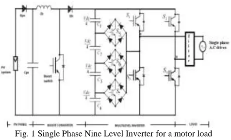
Fig. 1 Single Phase Nine Level Inverter for a motor load
It comprises a single-phase conventional H-bridge inverter, three bidirectional switches, and a capacitor voltage divider formed by C1, C2,C3 and C4, , as shown in Fig. 1.
The modified H-bridge topology is significantly advantageous over other topologies, i.e., less power switch, power diodes, and less capacitor for inverters of the same number of levels. Photovoltaic (PV) arrays were connected to the inverter via a dc–dc boost converter. The power generated by the inverter is to be delivered to induction Motor. The dc–dc boost converter was required because the PV arrays had a voltage that was lower than the single-phase voltage.. The LC-filter is modeled to obtain pure sine-wave and is given to drive a single-phase induction motor.. Proper switching of the inverter can produce nine output- voltage-levels (Vdc, 3Vdc/4, Vdc/2, Vdc/4, 0, Vdc/4, Vdc/2, -3Vdc/4,- Vdc) from the dc supply voltage. The proposed inverter’s operation can be divided into nine switching states.
The required nine levels of output voltage were generated as follows.
1) Maximum positive output (Vdc): S1 is ON, connecting the load positive terminal to Vdc, and S4 is ON, connecting the load negative terminal to ground. All other controlled switches are OFF; the voltage applied to the load terminals is Vdc. 2) Three-fourth positive output (3Vdc/4): The bidirectional switch S5 is ON, connecting the load positive terminal, and S4 is
ON, connecting the load negative terminal to ground. All other controlled switches are OFF; the voltage applied to the load terminals is 3Vdc/4.
3) Half of the positive output (Vdc/2): The bidirectional switch S6 is ON, connecting the load positive terminal, and S4 is ON, connecting the load negative terminal to ground. All other controlled switches are OFF; the voltage applied to the load terminals is Vdc/2.
4) One-fourth of the positive output (Vdc/4): The bidirectional switch S7 is ON, connecting the load positive terminal, and S4 is ON, connecting the load negative terminal to ground. All other controlled switches are OFF; the voltage applied to the load terminals is Vdc/4.
5) Zero output: This level can be produced by two switching combinations; switches S3 and S4 are ON, or S1 andS2 are ON, and all other controlled switches are OFF; terminal ab is a short circuit, and the voltage applied to the load terminals is zero. 6) 6. One-fourth negative output (−Vdc/4): The bidirectional switch S5 is ON, connecting the load positive terminal, and S2 is
ON, connecting the load negative terminal to Vdc. All other controlled switches are OFF; the voltage applied to the load terminals is −Vdc/4.
7) Half of the negative output (−Vdc/2): The bidirectional switch S6 is ON, connecting the load positive terminal, and S2 is ON, connecting the load negative terminal to ground. All other controlled switches are OFF; the voltage applied to the load terminals is −Vdc/2
8) Three-fourth negative output (−3Vdc/4): The bidirectional switch S7 is ON, connecting the load positive terminal, and S2 is ON, connecting the load negative terminal to ground. All other controlled switches are OFF; the voltage applied to the load terminals is −3Vdc/4.
9) Maximum negative output (−Vdc): S2 is ON; connecting the load negative terminal to Vdc, and S3 is ON, connecting the load positive terminal to ground. All other controlled switches are OFF; the voltage applied to the load terminals is −Vdc.
Table - 1
Output Voltage According To the Switches’ On Off Condition
Vo S1 S2 S3 S4 S5 S6 S7
Table I shows the switching combinations that generated the nine output-voltage levels (Vdc, 3Vdc/4, Vdc/2, Vdc/4, 0, , Vdc/4, Vdc/2, -3Vdc/4,- Vdc
Fig. 2: Block diagram of the overall system
III. MPPT CONTROL
Fig. 3: PV cell equivalent circuit
A common inherent drawback of PV and system is the intermittent nature of their energy source. Solar energy is present throughout the day, but the solar irradiation levels vary due to sun intensity and unpredictable shadows cast by clouds, birds, trees, etc. These drawbacks tend to make these renewable systems inefficient. However, by incorporating maximum power point tracking (MPPT) algorithms, the systems’ power transfer efficiency can be improved significantly.
Where
Iph = photocurrent, ID = diode current, I0= saturation current, A = ideality factor,
q = electronic charge 1.6x10⁻¹⁹,
kB = Boltzmann’s gas constant (1.38x10⁻²³), T = cell temperature,
Rs = series resistance, Rsh = shunt resistance,
Boost Converter
The output voltage which is greater than the input voltage. It consists of dc input voltage source Vs, boost inductor L, controlled switch S, diode D, filter capacitor C, and load resistance R. The circuit diagram of boost converter is shown in Fig.4Where d, is the duty ratio of dc to dc converter which is defined as the ratio of turn on time to that of total time. The boost converter steps up the voltage from PV array to the required value before feeding to the Nine-Level Inverter system.
IV. PULSE WIDTH MODULATION
In single pulse width modulation control there is only one pulse per half cycle and the output rms voltage is changed by varying the width of the pulse. The gating signals to the inverter are generated by comparing the rectangular control signal of amplitude Vc with triangular carrier signal Vcar.
V. FILTER
It is mainly used for two reasons
1) To convert the inverter (output square wave) into pure sinusoidal wave 2) To eliminate the higher order harmonics.
VI. CONTROL STRATERGY
Fuzzy Logic System
Today control systems are usually described by mathematical models that follow the laws of physics, stochastic models or models which have emerged from mathematical logic. A general difficulty of such constructed model is how to move from a given problem to a proper mathematical model. Undoubtedly, today’s advanced computer technology makes it possible; however managing such systems is still too complex. These complex systems can be simplified by employing a tolerance margin for a reasonable amount of imprecision, vagueness and uncertainty during the modelling phase. As an outcome, not completely perfect system comes to existence; nevertheless in most of the cases it is capable of solving the problem in appropriate way. Even missing input information has already turned out to be satisfactory in knowledge-based systems.
Table - 2 Fuzzy Rule
e\de NB NM NS ZE PS PM PB
NB NB NB NB NB NM NS ZE
NM NB NB NB NM NS ZE PS
NS NB NB NM NS ZE PS PM
ZE NB NM NS ZE PS PM PB
PS NM NS ZE PS PM PB PB
PM NS ZE PS PM PB PB PB
PB ZE PS PM PB PB PB PB
Fuzzy logic allows to lower complexity by allowing the use of imperfect information in sensible way. It can be implemented in hardware, software, or a combination of both. In other words, fuzzy logic approach to problems’ control mimics how a person would make decisions, only much faster
.
Fig.5 Membership Functions Editor: Fuzzy
VII. SIMULATION RESULT AND DISCUSSIONS
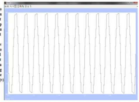
Fig. 6: Nine Level Output Voltage
Fig.5 shows the nine level output voltage of the single source nine level inverter. Output current of the inverter is almost sinusoidal in shape. This infers that the Total Harmonic Distortion (THD) of the single source nine level is low. When it is applied for grid connected applications, the power factor is almost unity providing a better operation. Since the THD of the inverter is low, it provides a better operation for the single phase induction motor.
Fig. 7: THD value for nine level inverter
VIII. COMPARISON OF PID & FUZZY LOGIC CONTROLLER
concluded that Proportional integrated Derivative (PID) controllers are widely used in process control applications, but they exhibit the poor performance when applied to systems, which are nonlinear, as controller tuning is difficult due to insufficient knowledge of the parameters of the system
Table – 3
Comparison of THD levels of inverters
CONTROLLER INVERTER LEVEL THD VALUE %
PID Five level output voltage 5.4
PID Seven level output voltage 3.9
FUZZYLOGIC Nine level output voltage 2.2
IX. CONCLUSION
THD in the nine-level inverter compared with that in the seven- -level inverters is an attractive solution for using AC system PV inverters. This system is successfully modeled to drive a single-phase induction motor for smooth starting by effectively eliminating of lower order harmonics, where higher order harmonics are eliminated by using Filter for better efficiency of its utilization which improves the motor performance.
REFERENCE
[1] Cecati.C, Ciancetta .F, and Siano P. (2010), “A multilevel inverter for photovoltaic systems with fuzzy logic control,” IEEE Trans. Ind. Electron., vol. 57,
no. 12, pp. 4115–4125.
[2] Corzine K.A,Wielebski M.W. Peng F.Z. and Wang J. (2004), “Control of cascaded multilevel inverters,” IEEE Trans. Power Electron., vol. 19, no. 3, pp.
732–738.
[3] Kjaer. S. B, Pedersen. J. K., and Blaabjerg F. (2005), “A review of single-phase grid connected inverters for photovoltaic modules,” IEEE Trans. Ind. Appl., vol. 41, no. 5, pp. 1292–1306.
[4] Nasrudin A. , Krismadinata Chaniago Rahim, Jeyraj Selvaraj (2014), Single-Phase Seven-Level Grid-Connected Inverter for Photovoltaic System”, IEEE
Trans. Ind. Electron., vol. 58, NO. 6.
[5] Ozdemir.E, Ozdemir.S, and Tolbert L.M (2009), “Fundamental-frequencymodulated six-level diode-clamped multilevel inverter for three-phase
stand-alone photovoltaic system,” IEEE Trans. Ind. Electron., vol. 56, no. 11, pp. 4407–4415.
[6] Rahim N.A, and Selvaraj .J (2010), “Multi-string five-level inverter with novel PWM control scheme for PV application,” IEEE Trans. Ind. Electron., vol.
57, no. 6, pp. 2111–2121.
[7] Renge M.M and Suryawanshi H.M. (2008), “Five-level diode clamped inverter to eliminate common mode voltage and reduce dv/dt in medium voltage
rating induction motor drives,” IEEE Trans. Power Electron., vol. 23, no. 4, pp. 1598–1160.
[8] Rodríguez J., Lai J. S., and. Peng F Z. (2002), “Multilevel inverters: A survey of topologies, controls, and pplications,” IEEE Trans. Ind. Electron., vol. 49,
no. 4, pp. 724–738.
[9] Selvaraj.J,and Rahim N. (2009) , “Multilevel inverter for grid-connected PV system employing digital PI controller,” IEEE Trans. Ind. Electron., vol. 56,
no. 1, pp. 149–158.