Comparative Study on DWT-OFDM and
FFT-OFDM Simulation Using Matlab Simulink
Manjunatha K#1, Mrs. Reshma M*2
#1
M.Tech Student, Dept of DECS, Visvedvaraya Institute of Advanced Technology (VIAT), Muddenahalli
#2
Asst. Professor, Dept of DECS, Visvedvaraya Institute of Advanced Technology (VIAT), Muddenahalli
Abstract Orthogonal Frequency Division Multiplexing (OFDM) is a technique for transmitting multicarrier signals. In OFDM a stream of data is transmitted and they are orthogonal to one another. Designing an OFDM will reduces the multipath effect at receiving end, by dividing the wide-band frequencies into many narrow-band frequencies this dividing process is carried out to avoid the interference that is caused during multipath effect. Guard bands are used to separate the symbols present in the OFDM, this guard band separation will resist the multipath effects. The basic idea of using FFT-OFDM was explained by different authors [1]. However, the applications of the OFDM are increasing rapidly in the fields of wired communication and wireless communication. High data rates are obtained using OFDM usually (FFT) Fast Fourier Transforms are used to get the orthogonal sub carriers. To overcome the disadvantages of FFT-OFDM, DWT-OFDM is considered. That is by replacing the DWT instead of FFT at the transmitting side and IDWT instead of IFFT at the receiving end [2]. This paper describes about designing an OFDM system using Discrete Wavelet Transforms (DWT) and simulation results are obtained using MATLAB.
Keywords —OFDM, FFT, IFFT, DWT, IDWT.
I. INTRODUCTION
Orthogonal Frequency Division Multiplexing (OFDM) is a modulation technique mainly suited for transmitting signals over dispersive medium. In OFDM the signals are orthogonal to each other, it means that they are totally independent to one another. Hence there arelot of advantages by using OFDM. Though there is some disadvantages like errors in frequency caused by local oscillator at the transmitting end and receiving end, it will avoid the ISI effect, efficiency of the bandwidth is high, it will reduces the burst errors and frequency selective fading. The wavelet transforms are considered along with the OFDM.
In OFDM wideband fading channels are divided into many narrow band sub channels it means that OFDM divides the complete spectrum into many
sub-channels. If these subs channel number exceeds to higher extent then each channel should be considered as flat. Since the OFDM is a modulation technique, hence each channels are modulated from lower data rates. This is considered because to avoid the overlapping of signals. Increasing the transmission channels results in decrease in data rate thus it increases the symbol period. Hence time delay is suppressed as shown in Figure 1. Figure 1(A) shows the spectrum of OFDM with guard bands, Figure 1(B) shows the subcarriers overlapping to save the bandwidth [1].
Figure 1: A) Spectrum of FDM showing guard Bands
B) Spectrum of OFDM showing overlapping subcarrier
OFDM systems are classified into three parts they are:
1. Frequency Division Multiplexing
2. Orthogonal Frequency Division Multiplexing
3. Multicarrier Communication
II. FFT/DWT BASED OFDM SYSTEM
International Journal of Engineering Trends and Technology (IJETT) – Volume-43 Number-5 -January 2017
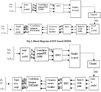
Fig 2: Block Diagram of FFT based OFDM
Fig 3: Block Diagram of DWT-OFDM
Since we are working on FFT/DWT based systems, thus the signals which are to be transmitted are converted from serial to parallel and they are processed by using QAM modulators and they are sent through the IFFT/IDWT block to perform the inverse operations. This output is passed through the parallel to serial block, this is carried out to pass the signal through the single channel then the received signal is converted into parallel since it has to perform FFT/DWT operations, before the FFT/DWT Block the signal may have some ISI effect, to eliminate that effect the signal has to pass through
the cyclic prefix block. After FFT/DWT operations the signal has to be equalized by using a frequency domain equalizer, then it is demodulated using QAM demodulator. Final it is converted into serial data by using parallel to serial converter.
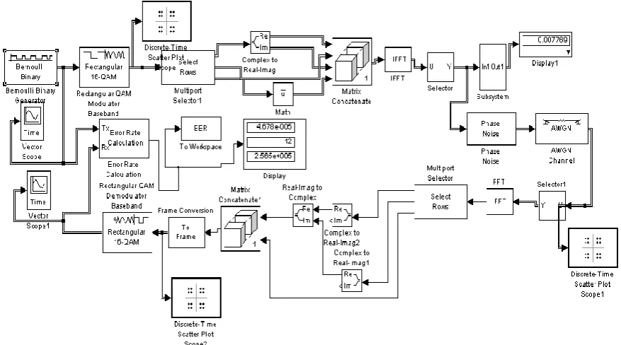
III.SIMULATIONS SETUP USING SIMULINK
Fig 4: FFT based OFDM using Simulink
Fig 5: DWT based OFDM using Simulink
A. Model Information:
b=4, M=2b.
Nfft=128, Nffth=Nfft/2. Nblock=Nffth*b. Ng=16; Guard interval. Nsym=Nfft+Ng.
The block diagram is implemented using matlab tools as shown in the above figure4 and figure5
IV.SIMULATION RESULTS
International Journal of Engineering Trends and Technology (IJETT) – Volume-43 Number-5 -January 2017
Phase
Noise
level
QAM
QPSK
FSK
-5
0.07617 0.4818 0.5156
-6
0.07292 0.4792 0.5156
-7
0.07227 0.4727 0.5234
-8
0.07292 0.4674 0.5234
-9
0.07096 0.4570 0.5296
-10
0.07031 0.4596 0.5322
Table1: BER comparison of different modulation Techniques
Phase
Noise
level
16-Bit
CP
40-Bit
CP
60-Bit
CP
-5
0.07617 0.08891 0.09219
-6
0.07292 0.07969 0.09141
-7
0.07227 0.07969 0.09219
-8
0.07292 0.07813 0.09062
-9
0.07096 0.07969 0.08984
-10
0.07031 0.07813 0.08906
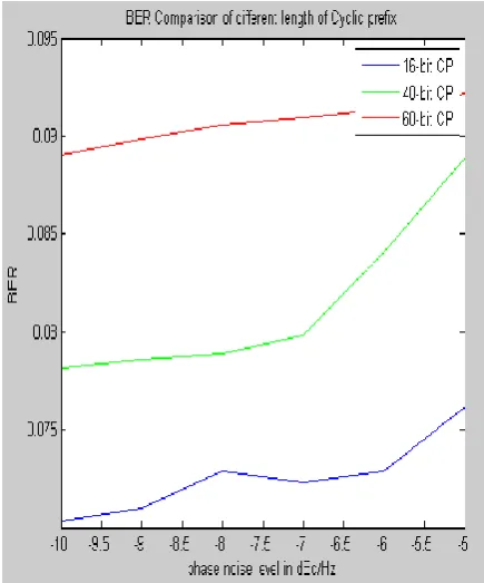
Table2: The BER comparison of different length of cyclic prefix addition.
Phase
Noise
level
Cyclic
prefix
Cyclic
Suffix
-5
0.07617
0.4336
-6
0.07292
0.4336
-7
0.07227
0.4297
-8
0.07292
0.4258
-9
0.07096
0.4258
-10
0.07031
0.4233
Table3: BER Performance Comparison of Cyclic prefix and Cyclic suffix addition.
Fig 6: BER Performance of Different Modulation Techniques
Fig7: BER Performance of Different
Fig8: BER Performance of cyclic prefix
and suffix
Fig9: Constellation Diagram of
input signal
Fig10: Constellation Diagram of output
signal
V. CONCLUSION
An OFDM system is simulated successfully for FFT-OFDM and DWT-FFT-OFDM using simulink models in MATLAB. It is observed that DWT-OFDM provides low BER compared to FFT-OFDM.
REFERENCES
[1] S.S.Ghorpade and S.V.Sankpal “Behaviour of OFDM System using MATLAB Simulation”,International Journal of Advanced Computer Research (ISSN (print), Volume-3 Number-2 Issue-10 June-2013.
[2] W. Saad, N. El-Fishawy, S. EL-Rabaie, and M. Shokair “An Efficient Technique for OFDM System Using Discrete Wavelet Transform”, Springer-Verlag Berlin Heidelberg 2010.
[3] Rohitbodhe, Rohitbodhe and Shirishjoshi “Design of simulink model for OFDM and comparison of FFT-OFDM and DWT-OFDM”, International Journal of Engineering Science and Technology (IJEST), Vol. 4 no. 05 May 2012. [4] D. Xiao, X. Liao, and P. Wei, “Analysis and improvement
of a chaosbased image encryption algorithm,” Chaos Solit. Fract., vol. 40, no. 5, pp. 2191–2199, 2009.
[5] C. K. Chan and L. M. Cheng, “Hiding data in images by simple LSB substitution,” Pattern Recognit.., vol. 37, pp. 469–474, Mar. 2004.
[6] Z. Ni, Y. Q. Shi, N. Ansari, and W. Su, “Reversible data hiding,” IEEE Trans. Circuits Syst. Video Technol., vol. 16, no. 3, pp. 354–362, Mar. 2006.
[7] J. Tian, “Reversible data embedding using a difference expansion,” IEEE Trans. Circuits Syst. Video Technol., vol. 13, no. 8, pp. 890–896, Aug. 2003.
![Figure 1(B) shows the subcarriers overlapping to save the bandwidth [1].](https://thumb-us.123doks.com/thumbv2/123dok_us/8590448.1721024/1.595.311.524.344.477/figure-b-shows-subcarriers-overlapping-save-bandwidth.webp)