Analysis, Design and Implementation of
Automotive Breaking System Based on Gold
Sequence with Correlation RADAR
Shrikant Kumar
1, Dr. Paresh Rawat
2Department of Electronics and Communication, TCST Bhopal RGPV India
Abstract: Automation technologies have provided us with various systems that reduce the time and human error. Particularly the heavy vehicles like aircraft and submarine are very difficult to operate manually in heavy traffic. As personally one is very careful about, otherwise damage being caused to the system. In view of this to provide a proper guidance to the system in heavy traffic, means are provided. We have enhanced the facility by using automatic breaking when an obstacle is close by. Therefore, in this paper we propose an “Automatic Breaking system” to prevent collision by using correlated sequences for correlation radar to detect obstacles. The “Automatic Breaking system” will process the signal activities and their echo’s and controls the system to prevent accidents caused by careless driving or difficulty in detecting objects in the path. In this controlling logic is implemented on VHDL using Xilinx software. The system designed by VHDL keeps a distance between the object and system to prevent accidents
.
Keywords: PN Sequence, Correlation Radar, Avoid collision, Doppler Effect.
1. INTRODUCTION
The basic principle of operation of primary radio detection and ranging is easy to know. The implementation and operation of primary radars systems involve a large vary of disciplines like building works, significant mechanical and technology, high power microwave engineering, and advanced high speed signal and processing techniques [5]. A {radar or microwave radio detection and ranging or radio detection and ranging or radiolocation or measuring instrument or measuring system or measuring device} system incorporates a transmitter that emits radio waves known as radar signals in planned directions [4]. Once these inherit contact with associate object they're typically mirrored and/or scattered in several directions. The (radar or microwave radio detection and ranging or radio detection and ranging or radiolocation or measuring instrument or measuring system or measuring device) signals that square
measure mirrored back towards the transmitter square measure the fascinating ones that create radar work. If the thing is moving either nearer or farther away, there's a small amendment within the frequency of the radio waves, thanks to the propagation.
This constant speed permits the determination of the gap between the reflective objects (airplanes, ships or cars) and therefore the radio detection and ranging web site by measurement the period of time of the transmitted pulse [1]. This energy usually travels through area during a line, and can vary solely slightly thanks to part and weather. By victimization of special radio detection and ranging antennas this energy may be targeted into a desired direction. So the direction (in angle and elevation) of the reflective objects may be measured. These principles will primarily be enforced during a radio detection and ranging system, and permit the determination of the gap, the direction and therefore the height of the reflective object.
One needs to resolve 2 issues with this principle: • prevent an immediate association of the transmitted energy into the receiver (feedback connection),
• Assign the received echoes to a time system to be able to do run time measure.
A direct association of the transmitted energy into the receiver may be prevented by:
• Spatial separation of the transmission antenna and therefore the receiving antenna, e.g. the aim is light by a robust transmitter and therefore the receiver is found within the missile flying direction towards the aim;
2. CORRELATION RADAR
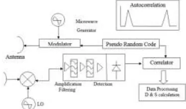
The most vital radio detection and ranging utilized in this project is correlation radio detection and ranging whose operate is to produce the matching between transmitted and received signal and therefore the matched signal is send to comparator for comparison the information Digital repose correlation operate is given higher than .The classical correlation is that the add of sample product X and Y, with Y being solely shifted in time. Zeros replace gaps within the shifted sequence.
Figure 1 Block Diagram of Correlation Radar We don’t used classical correlation operate however a cyclic one is employed. Rather than a straightforward time shift the cyclic correlation perform a circular permutation of the second sequence.
Pseudo random sequence may be unipolar or bipolar. For unipolar sequence, chips will take the worth zero and one once a bipolar sequence will have values -1 or one. We used unipolar sequences and this sequence is generated by victimization register. Pseudo random binary sequences square measure generated victimization some specific outputs of the register's flip flops square measure fed-back via a XOR circuit. This feedback is completed so the register plays its (2n-1) attainable states, like n is that the variety of flip-flops forming the register. Thus, we tend to get what's known as a most length sequence.
Where Cxy is the correlation, N is the number of samples and k is the time shift.
3. PAST WORK
The basic configuration or block diagrams of sensing approach for determination of obstacles in reverse direction. In this diagram Figure 2 showing that sensor senses the obstacles and send signal to the
FGPA controller, this controller circuit done the controlling process or the process done by this section according to the logic. Generally we already know that in digital world output comes out only in 0’s and 1’s. These kinds of outcomes logic go to the mechanical part of system than breaks will on and off according to them.
Figure 2 Block Diagram Sensing Circuit
Figure 3 Simulation Results of TSOP module interfaced with FPGA
4. PROPOSED WORK
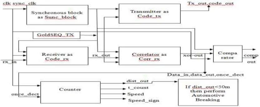
diagram of correlate measuring system is shown in Figure 4.
Figure 4 Block diagram of correlation radar used in anti-collision system
Figure 5 Block Diagram of Breaking Concept
Figure 6 Flow Chart for Automotive Breaking System
Equation and VHDL codes (Function) used for each block of flow chart is given below
1. Open New Project
2. Write Code for synchronous block, Transmitter, receiver, correlation, comparator, counter, automotive breaking modules
3. Link all the modules to create correlation RADAR modules.
4. Now create RTL for correlation RADAR. 5. Write Test bench for RADAR.
6. Simulate the RADAR to observe distance, relative speed and speed sign and perform automotive breaking system if obstacle is too near by the system to avoid collision between two obstacles.
7. If obstacle is too near by the system like aircraft, submarine’s and others perform automotive breaking operation and slow down the speed of the system like aircraft, submarine’s and others according to relative speed, direction or speed sign and avoid collision.
4.1 Proposed MATLAB Algorithm
1. To clear all variable and command content to close all previously opened windows following MATLAB function are used.
2. clc 3. Clear all, 4. Close all,
6. Plot PN seq 1 and PN seq 2 for PRBS and PN seq 1, PN seq 2, PN seq 3, PN seq 4 for GOLD sequence.
7. Add Noise to PRBS and GOLD sequence. 8. Correlate the PN seq 1 and PN seq 2 to get
xor_sum-pn.
9. And again correlate PN seq 1 and PN seq 2 to get gs_seq-out and PN seq 3 and PN seq 4 to get gs_seq_out_1.
10. Correlate the result of gs_seq _out and gs_seq_out_1 shows gold sequence is better than PN sequence.
5. RESULTS & THEIR DISCUSSION 5.1 Xilinx Simulation Results
Automotive breaking module basically based on correlation property of radar. Correlation radar consists of transmitter and receiver. This proposed methodology is a RTL and logical methodology which has implemented using VHDL code and Xilinxs 14.3 as a platform. In this proposal we
synthesized the RTL module and their logical module and also enhance the compatibility and reduce the complexity. Simulation results have generated using Xilinxs 14.3 in their we synthesized nine module and determine obstacles distance, relative motion, direction, automotive breaking modules
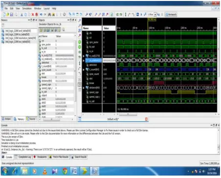
Figure 7 Shows the correlation between transmitted and received signal
As shown in Figure 7 show that the correlation between transmitted and received signal when clock =1, sync pulse
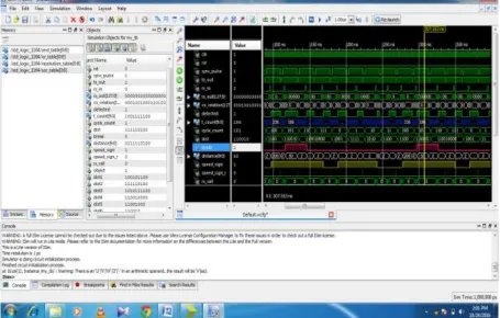
Figure 8 shows the breaking operation of the correlation radar
As shown in Figure 8 shows the output at clock =1, sync pulse =1, but receiver output is zero and correlation is obtained between transmitted and received pulse and distance is obtained at 50. Correlation is obtained between transmitted and received pulse at count 186, cycle count 101,tx_out =1, rx_in =0, and obstacles is detected and Obtained Output at correlation 307.553 ns with obstacle moving towards the system. Obstacle direction shows
by the help of speed sign and this time it is 1, this shows that the direction and relative motion of obstacle towards the system. There is also system performing breaking operation and it can be seen by the help of break option, this time it has indicated 1. The system will slowdown automatically and avoid collision.
5.2 Matlab Simulation Results:
Figure 10 output of correlation with xor_gs_seq. of gold sequence
The above simulation results as shown in Figure 9 and 10 are generated for 1024 bit long gold-sequence from the simulation results we can conclude that the gold-sequence codes shows better auto correlation value even in presence of more noise in comparison with m-sequences and also it shows no peaks with other gold-sequences which makes it better choice for automotive applications.
Some other important conclusions drawn by simulation are:
1 More number of sequences than m-sequences. 2 Good-sequence pairs have no peaks on cross- correlation values.
All the points mentioned above makes it a good choice for our system. Hence in MATLAB we can proof the mathematical concept of PRBS which is simulated by VHDL.
6. CONCLUSION
In this paper we observe that we need a solution for detection in presence of noise as well as present of other signals and according to analysis of the simulation results above the diagram shows that the gold codes gives better performance in presence of noise & other interfacing radar signals although it needs larger number of gates hence its implementation on VHDL could increase the cost slightly but considering overall performance its better choice.
After a short state of the art on previous works car anti-collision systems, we have described the principle of distance measurement with correlation radar and gave our contributions on real time implementation of this radar. Many improvements were performed on the correlation architecture. This concerns optimized multipliers and improvements on adder layers. A particular attention was paid to our correlation generator. The major interest of the latter is that it is able to generate the VHDL code of the correlation including all its components, in an automatic way.
The next points give some advantages of the correlation generator:
Fast synthesis: correlation synthesis becomes very fast and easy (the generator executes in less
Than a second),
A flexible tool: to generate a new correlation, we only need to enter the desired correlation parameters such as random sequence length or data bus width, etc.
Robustness: if an error occurs in the synthesis, it is much more efficient and easier to fix it once on the correlation generator than to do it in each file of the whole project.
The correlation was implemented on an RTL for real time application. Two tests were performed to check the good functioning of the VHDL code generator and the correlation itself. In the second test a distance measurement was performed. The results confirmed the good functioning of the correlation and the correlation generator.
7. REFERENCES
[1] Divya Thakur, Prof. A. P. Thakare, “Implementation of Automatic Reverse Braking System on FGPA” IETE 46th Mid Term Symposium “Impact of Technology on Skill Development” MTS 2015.
[2] Pravin P Ashtankar, Sanjay S .dorle ,“Design Apporch For Anti-Collision Mechanism between vechicle to vechicle for improving Safety operation in Intelligent transportation system in 2009
[3] Hung Youpeng, Zhang Haibo, ”Radar Infrared sensor Track Correlation Algorithm Using Gray Correlative Analysis” in 2009
[4] Obstacle detection, obstacle avoidance and anti-collision system using a COTS multi-beam forward looking sonar proposed by Ken Teo, Kai Wei Ong and Hoe Chee Lai.in 2009
[5] Neelappa, Dr. N. G. Kurahatti, “Novel Method for Design and Implementation of Low Power FPGA based RFID System” 978-1-4799-6085-9/15/$31.00 ©2015 IEEE.
[6] Chika Sugimoto, Yasuhisa Nakamura, Takuya Hashimoto, ”Development of pedestrian-to-vehicle communication system prototype for pedestrian safety using both wide-area and direct communication in 2008 [7] L. Sakkila , P. Deloof. Real time processing unit used
for an anti-collision road radar system in 2006 [8] C.Tatkeu, P.deloof, Y.Elhillai “A Cooperative radar
system for collision avoidance and communication between vehicles” in 2006
[9] Retro-directive Noise Correlation Radar with Extremely Low Acquisition Time Shalabh Gupta and E. R. Brown, Fellow, IEEE University of California at Los Angeles, CA 90095 in 2003.
[10] M.Lienard and P.Degauque “CORRELATION RADAR: An optimization of code generator architecture in 2003.