Improvement of Transmission Parameters in a
9-Bus System with Unified Power Flow Controller
Catherine T. J. Vinod Jacob Sam
Department of Electrical Engineering Department of Electrical Engineering
RMK College of Engineering and Technology BHEL
Abstract
Improvement in power flow by the deliberate placement of UPFC is demonstrated in this paper. The demonstration uses a nine bus system to show the effectiveness of UPFC when a high higher load impacts the system. The circuit is first simulated first without a UPFC and the power flow studied. Simulation with the help of MATLAB software amply demonstrates the controllability of transmission parameters with the introduction of UPFC. Dynamic performance is also seen to be improving by introduction of UPFC at a strategic location in the system.
Keywords: UPFC, VSC, Compensation, Phase Regulation, Power flow, Voltage Regulation
________________________________________________________________________________________________________
I.
INTRODUCTION
Power demand is always on the rise due to the economic growth in India. While load demand is rising, generation from existing power stations or renovated stations are not increasing in the same proportion with the demand. As the installation of new power plants are getting entangled with several roadblocks, be it environmental clearance, coal linkage or financial tie ups, need of the hour is enhancement of capabilities of the existing transmission lines. Until recently, with the exception of SVC, all plant components used in high voltage transmission to provide voltage and power flow control, were equipment based on electro-mechanical topology, which severely impaired the effectiveness of the intended control actions, particularly during fast changing operating conditions. This situation has begun to change, building on the operational experience afforded by many SVC installations. Due to the tremendous growth in power electronics valves and their control a vast array of new power electronic based controllers has been developed. FACTS devices have been extensively used for the improvement in the power transmission capability of a transmission line[1]. FACTS devices made their debut in 1980s and have grown with the introduction of Voltage Source Converters in 1990s. The most versatile of this group is the Unified Power Flow Controller (UPFC). The UPFC allows simultaneous control of active and reactive power flows and voltage magnitude at the UPFC terminals. Thus we can say that it provides three degrees of freedom, voltage regulation, series compensation along with phase shifting [2][3]. The UPFC helps to regulate the power flow, thus allowing the loading of transmission lines near to their thermal limits.[5]. In addition to these, UPFC has the capabilities of mitigating system oscillations, improving transient stability and providing voltage support [7] [8]. Many studies and analysis have been carried about the performance of UPFC since its introduction [10]-[15]. The studies indicate that UPFC can be used for controlling the real and reactive power flows.
II.
UNIFIED POWER FLOW CONTROLLER
Construction of UPFC is achieved with two voltage source converters (VSC), one series and other one shunt, connected to the transmission line through a shunt transformer and a series transformer. The basic VSC consists of six switches made up of six IGBTs with antiparallel diodes across them. The two converters share a common DC link by means of a capacitor. The schematic of a UPFC is depicted below.
III.
OPERATION OF UPFC
When we consider each converter separately, it is seen that the shunt converter working alone can be considered as the Static Synchronous Compensator (STATCOM). This is capable of supplying or absorbing real power to the transmission line by adjusting the phase shift between the converter output voltage and the voltage at the point of connection of the shunt converter the to the transmission line. By adjusting the amplitude of the output of the converter to be above or below of that of the bus, the current can be made to flow from the converter to the bus or from the bus to the converter indicating reactive power generation or absorption. Thus the shunt converter is capable of exchanging the real power as well as the reactive power with the transmission line.
Static Synchronous Series Compensator (SSSC) when acting alone becomes the series converter of the UPFC. As the name indicates, it is connected in series with the transmission line through the series transformer. The output of the converter is a voltage of variable magnitude and phase angle. Thus the series converter can vary the effective impedance of the transmission line by injecting a voltage of appropriate magnitude and phase angle with reference to the line current. Thus it is capable of exchange of real as well as reactive power with the transmission line.
When these two converters are made to share the same DC source, we get the F TS UPF I VS 3 real and reactive power with the lines. There cannot be any exchange of reactive power between the converters due to the DC link. The role of shunt converter is mainly to meet the real power requirement of the series converter.
The placement of UPFC is to be carefully decided to give optimum improvement if the transmission parameters
Operating Modes of UPFC: A.
How a UPFC connected in a system can provide voltage regulation as well as control of and reactive power flow was explained above. The series and shunt regulators are responsible for this achievement. Depending upon which converter is utilised, we can have different modes of operation for the UPFC.
Shunt Converter: 1)
The shunt converter injects a variable shunt voltage with the transmission line such that the current flow to the shunt converter has a real component which can produce the real power. This real power meets the power loss in the series converter. The reactive power exchange between the shunt converter and transmission line can independently provide the shunt compensation and hence maintain the voltage constant, thereby providing voltage regulation. The shunt reactive current can be made leading or lagging to meet the required capacitive or inductive Var request. Thus we can see that the shunt converter can be operated either in Automatic voltage regulation mode or Var control mode.
Series Converter: 2)
The series converter is controlled to inject a voltage of variable magnitude as well as phase angle. Depending on the phase angle values we can realise different modes of operation for the UPFC. If the injected voltage is in phase with the sending end voltage, we can achieve voltage regulation. By injecting a voltage orthogonal to the line current, the net voltage drop across the line impedance can be controlled thereby achieving reactive compensation. By injecting a voltage V3 of desired magnitude, we can cause a shift in the phase angle of the sending end voltage Vs.[3][4]
By controlling the terminal voltage, phase angle and line impedance simultaneously, the UPFC can be made to perform power flow control.
Thus there can be four modes of operation for the series converter as follows: Direct voltage injection mode
Line impedance compensation mode Phase angle regulation mode Automatic power flow control
IV.
P
OWER FLOW EQUATIONSThe UPFC is connected at the sending end of a bus whose voltage has to be regulated. The converter can be shown by a variable voltage source representing the voltage injection.
If VS represents the sending end voltage, VR the receiving end voltage and Vse the voltage injected by the UPFC , then we can find the power flows in the transmission line as follows.
Without UPFC,
Fig. 2: Power Flow
Though the UPFC can be connected anywhere in the line, strategic placement improves power flow. Here it is connected at the sending end bus to regulate the power flow. The series converter injects a voltage VSE to make the voltage at the receiving end regulated also. The shunt converter has a voltage Vsh at its ac terminals.
Fig. 3: UPFC in a transmission line.
When the UPFC is connected in the bus where it is required to improve the power flows, the equations get modified as written below.
)
'
Where Pupfc and Qupfc are the additional power flows due to the insertion of UPFC in the line.
This is the most simplified form of representing the UPFC[7]. This is an effective model, but it lacks control flexibility. Flexibility of the model can be improved by considering the two converters as two coordinated voltage sources. The active power demand by the series converter is met by the shunt converter. If the converter switches are assumed to be lossless, the injected active and reactive powers can be written individually for shunt and series converters separately.
V.
SIMULATION RESULTS
It can be seen that in the absence of UPFC with the loads of 600MW and 1000MVAR are connected to the system, the voltage of bus3 suddenly dips to 477.3KV. If the UPFC is connected to the bus3, then we can see that by injecting a voltage of 1pu, the bus 3 voltage can be regulated at 494.3KV. Even the power flow is found to be improved from a low value of 82.9MW to 121.6MW thus proving the usefulness of UPFC in improving the performance of transmission lines.
Table -I: System Details
Sl. No Test System Details
1 Generators Plant1
Plant2
1000MW 1200MW
2 Line inductance
L1 L2 L3-L6
66.95mH 46.685mH 46.685mH
3 Transformers 1000MVA
800MVA
4 Load Load1
Load2
200MW 600MW, 600MVar
5 UPFC
Series Converter
Shunt Converter
10% injection (100MW)
1pu
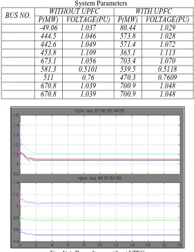
Table II represents the effectiveness of UPFC in a transmission system. On comparison of the simulation results, we can see that there is considerable improvement in the voltage levels and power flow when the UPFC is connected in the system. Figure 4(a) represents the voltage levels of the nine buses without any compensation.
Table -II: System Parameters
BUS NO. WITHOUT UPFC WITH UPFC
P(MW) VOLTAGE(PU) P(MW) VOLTAGE(PU)
-49.06 1.037 80.44 1.029
444.5 1.046 573.8 1.028
442.6 1.049 571.4 1.072
453.8 1.109 365.1 1.113
673.1 1.056 703.4 1.070
581.3 0.5101 539.5 0.5118
511 0.76 470.3 0.7609
670.8 1.039 700.9 1.048
670.8 1.039 700.9 1.048
Fig. 4(b): Power flows in Buses 1-9 without UPFC
Fig. 5(a): Bus voltages with UPFC
VI.
CONCLUSIONS
MATLAB software is made use of to simulate the UPFC model connected to the bus-3 in a 9-bus transmission system. The system is simulated to prove the effectiveness of UPFC in regulating the voltage as well as improving the power flow through the transmission line where sudden switching of highly reactive load is found to be deteriorating the quality of ower transmission. The experimental results can be validated for different positioning of UPFC in other lines.
REFERENCES
[1] N G H L G L “U F TS ” IEEE P 2
[2] L D T R R E “ T U f P f : N P T ”IEEE
transactions on Power Delivery, Vol 10, No.2,pp.1085- 1097, April1995.
[3] H k F Y W bb H f k “ f U f P f ” IEEE Transactions on Power
Electronics, vol. 14, No. 6 pp. 1021–1026, Nov. 1999.
[4] K R P M K k “ D S f U f P F ” IEEE T P r Delivery., vol. 13, pp.
1348–1354, Oct. 1998
[5] O H b M E G z L f N H ”S b f U f P F ” 13 I national Middle East
Power System Conference (MEPCON 2009), Assiut University, Assiut, Egypt, 20-23 December 2009. (2009): 593-597.
[6] S T K G T D “S f R R P F UPF T L ” J f
Theoretical and Applied Information Technology, 2008.
[7] Nabavi Niaki, S.A., Iravani, M.R, "Steady-S D M f U f P F UPF f P S ” IEEE Trans. Power System, pp.1937-1943, Nov. 1996.
[8] D L Y Z L ” f f f ” P E S y Winter Meeting, 2002, IEEE.
[9] Q Y S D R L E N T M U “D f U f P F ” IEEE T P Delivery., vol. 9,
No.2, pp. 508–514, April1996.
[10] N F M S M B “S P U f P F UPF : S ” E J f S f R
vol.30,No.4, pp. 677-684,2009.
[11] Edris, A. Mehraban, A.S., Rahman, M., Gyugyi, L., Arabi, S., Rietman, T.,'Cotnrolling the Flow of Real and Reactive Power', IEEE Computer Application
in Power, January 1998, p. 20-25
[12] Noroozian, M., Angquist, L., Ghandhari, M., Andersson, G., 'Use of UPFC for Optimal Power Flow Control, IEEE Transactions on Power Delivery, Vol.
12, No. 4, October 1997, p. 1629-1634
[13] L. Dong, M. L. Crow, Z. Yang, C. Shen L Z S “ f b F TS f b ” IEEE T P S