How To Generate Distributed Software
Components From Centralized Ones?
Abdelhak Seriai*, Gautier Bastide* and Mourad Oussalah**
* Ecole des Mines de Douai, 941 rue Charles Bourseul, 59508 Douai, FranceEmail: {seriai, bastide}@ensm-douai.fr
** LINA, universite´de Nantes, 2 rue de la Houssini`ere, 44322 Nantes, France Email: [email protected]
Abstract— Adapting software components to be used in a particular application is a crucial issue in software compo-nent based technology. In fact, software compocompo-nents can be used in contexts with characteristics different from those envisaged when designing the component. Centralized or distributed deployment infrastructure can be one of these assumptions. Thus, a component can be designed as a mono-lithic unit to be deployed on a centralized infrastructure, nevertheless the used infrastructure needs the component to be distributed. In this paper, we propose an approach allowing us to transform a centralized software component into a distributed one. Our technique is based on refactoring and fragmentation of component source-code.
Index Terms— Software component, adaptation, restructura-tion, distriburestructura-tion, refactoring.
I. INTRODUCTION
Component-based software engineering (CBSE) [1], [2] focuses on reducing application development costs by assembling reusable components like COTS [3] (Commercial-Off-The-Shelf). However, in many cases, existing components can not be used in an ad-hoc way. In fact, using a software component in a different manner than for which it was designed is a challenge because the new use-context may be inconsistent with assumptions made by the component. Deployment infrastructure may be one of these assumptions. For example, a software component may be designed as a monolithic unit to be deployed on a centralized infrastructure and, due to load balancing performance, security policy or other motiva-tions, this component has to be distributed. The solution consists in adapting this component to its distributed use context.
Therefore, in this paper, we propose an approach aim-ing at transformaim-ing an object-oriented monolithic and cen-tralized software component by integrating distribution fa-cilities [4]. Our approach is based on two transformations. The first one consists in refactoring component structure in order to create a composite-component (i.e. fragmented structure), while preserving component’s behavior [5].
This paper is based on “Transformation of centralized software components into distributed ones by code refactoring,” by A. Seriai, G. Bastide and M. Oussalah, which appeared in the Proceedings of the International Conference on Distributed Applications and Interoperable Systems (DAIS 2006), Bologna, Italy, June 2006. c2006 LNCS.
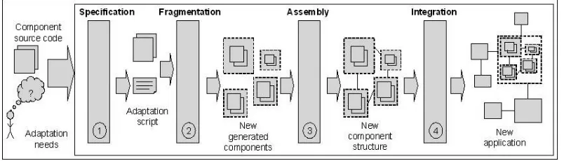
This transformation is achieved through a process com-posed of four stages. First, following the available infras-tructure, the needed distribution configuration is expressed in a declarative style. Next, the monolithic component is fragmented to fulfill the distribution specification given during the first stage. After, components generated as fragmentation result are assembled. Finally, the compo-nent assembly is wrapped into a composite-compocompo-nent which is integrated into the application.
The second transformation makes the generated composite-component distributed. In fact, the refactoring process applied to a monolithic centralized component generates a composite one but still with centralized con-stituents. So, in order to create a distributed composite-component, we need to transform local composition links between its constituents into remote ones. Remote links reflect the distributed configuration specified for the adapted component services.
We discuss the proposed approach in the rest of this paper as follows. Section II presents an example of ex-perimentation that illustrates our approach. Section III and IV detail respectively, the refactoring process allowing us to fragment a component and next, the integration of the distribution mechanisms. Section V gives details on source-code instrumentation. In section VI, we present Scorpio, a prototype which implements our approach. Section VII reviews related work. Conclusion and future works are provided in section VIII.
II. EXAMPLE OF ILLUSTRATION:A SHARED-DIARY COMPONENT
In order to illustrate our purpose, we use throughout this paper an example of a software component providing services of a shared-diary system which can be accessible to multiple users. It allows users to store and consult the personal diaries of each member of a group and coordinates dependent events, stored or generated by these diaries. The shared-diary component provides the following services:
1) Managing personal diary. This includes authen-tication, consulting events (e.g. meeting, activity, project), querying the diary, etc. These services are provided through the Diary interface.
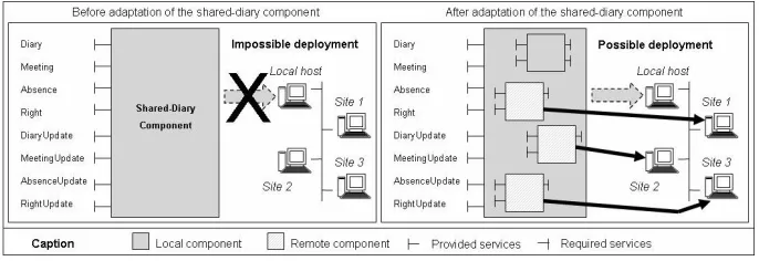
Figure 1. Transformation of the shared-diary component into a distributed one
meeting where the date and the list of the concerned persons are given as parameters, services returning possible dates to organize a meeting of some peo-ple, etc. These services are provided through the
Meeting interface.
3) Managing absence. This includes services permit-ting users to verify the possibility to add an absence event, to consult all the absence dates of one or some persons, etc. These services are provided through the Absence interface.
4) Right management. This includes services concern-ing absence right attribution, service related to di-aries initialization, etc. These services are provided through the Right interface.
5) Updating diary, meeting dates, absence dates and absence rights of a person. These services are provided, respectively, through DiaryUpdate,
MeetingUpdate, AbsenceUpdate and RightUpdate
interfaces.
We consider that this component is a monolithic and centralized one. Also, we assume that, due to the con-sidered load balancing policy, defined for the available deployment infrastructure, this component cannot be de-ployed on only one host. So, our goal is to transform this component for deploying it on a distributed infrastructure (Fig. 1). This result may be obtained by the fragmentation of the shared-diary component into four new components: 1) Diary-Manager component which provides Diary
and DiaryUpdate interfaces,
2) DataBase-Manager component which provides
Right and RightUpdate interfaces,
3) Absence-Manager component which provides
Ab-sence and AbAb-senceUpdate interfaces,
4) Meeting-Manager component which provides
Meet-ing and MeetMeet-ingUpdate interfaces.
In order to take into account deployment context, the
Diary-Manager component will be deployed on the local
host whereas the DataBase-Manager, Absence-Manager and Meeting-Manager components will be deployed re-spectively on site1, site2 and site3 (remote hosts).
III. FROM A MONOLITHIC COMPONENT TO A
COMPOSITE-COMPONENT
The first transformation to obtain a distributed com-ponent from a monolithic centralized one consists in
refactoring component source-code through the fragmen-tation of its structure. As we mentioned it previously, the component refactoring process (Fig. 2) is based on four stages which are detailed below.
A. Specification of the transformation result
The first stage of the transformation process is the specification of the needed results. This specification consists in the generation of a script which we call "adaptation script". In fact, every generated-component is specified by indicating its provided interfaces and its de-ployment host. The script syntax is given below. Symbols "+", "∗" indicate respectively one or more and zero or more elements. "{}" symbolizes a set of elements. When an interface is defined in several generated-components, symbol "||" associated with the interface name indicates that this interface must be that which is used by the rest of the application. To guaranty the correctness of this specification, we define some control operations in order to check that each new sub-component provides a set of interfaces which must be included in the interface set of the component to be adapted. Moreover, the union of these subsets must be equal to the set of interfaces provided by the initial component.
S t r u c t u A d a p t ( CompToAdapt ,
{CompDef = < { P o r t D e f = { [ | | ] I n t e r f a c e D e f } + } + ? > , < h o s t ? > }∗)
To illustrate this stage, let us reconsider our example of the shared-diary application. The goal of this com-ponent transformation is to reorganize services provided by this one in four new generated-components (e.g.
Diary-Manager, DataBase-Manager, Absence-Manager, Meeting-Manager) which are deployed on distinguished
hosts. The script allowing the application administrator to specify the needed structure is given below.
S t r u c t u A d a p t ( S h a r e d−D i a r y ,
{ D i a r y−Manager=<{P−D i a r y = D i a r y , D i a r y U p d a t e } >} { D a t a B a s e−Manager=<{P−DB= R i g h t , R i g h t U p d a t e } > ,
< s i t e 1 >}
{ Absence−Manager=<{P−Abs=Absence , A b s e n c e U p d a t e } > , < s i t e 2 >}
{ M e e t i n g−Manager=<{P−Meet= M e e t i n g , M e e t i n g U p d a t e} > , < s i t e 3 >}
Figure 2. Software component refactoring process
B. Component fragmentation
Specification done during the previous stage is used to refactor component structure. Component refactoring consists in fragmenting this component into a set of new generated-components, while guaranteeing the component integrity and coherence. This stage is based on component source-code analysis.
1) Fragmentation control: Component source-code refactoring must be realized without any change on this component’s behavior. Thus, two criteria must be checked: integrity of generated-components and coher-ence of their respective states.
• Generated-component integrity. The implementation
of each generated-component must be guaranteed to be sound. The soundness of this code1 implies
that it must be syntactically and semantically correct (i.e. code must be conformed to the corresponding object-oriented grammatical and semantic language rules), complete (i.e. dependent code elements must be accessible one to the others) and coherent (i.e. the behavior corresponding to a generated-component must be conformed to the matching local behavior in the monolithic component).
• Generated-component coherence. The outside
behav-ior made by the generated-components must be the same as the monolithic component’s behavior. That implies that local behaviors of generated-components must be coherent, the ones compared to the oth-ers. This requires that local behaviors corresponding respectively to the generated-components which are semantically related to other behaviors in other com-ponents must be identified to ensure their correlation.
2) Code analysis and fragmentation: The
fragmen-tation which aims at generating new software compo-nents is realized by analyzing the monolithic component source-code, determining for each new component to be generated its corresponding code, separating these codes, one from the others, and determining existing dependencies between them. These steps are mainly based on building, for each component to generate, its SBDG (i.e. Structural and Behavioral Dependency Graph). A SBDG is a graph where nodes are structural elements
1Proof of the satisfaction of this soundness criteria by the proposed
refactoring approach is out of this paper scope.
and arcs are the different forms of dependencies ex-isting between these elements. Structural elements may be external (e.g. ports, interfaces, implementation class and methods matched with services provided by these interfaces) or internal (e.g. internal methods and inner classes) ones. Dependencies between structural elements are of two types: structural and behavioral dependencies. Structural dependencies correspond to composition rela-tionships between structural elements. Thus, a software component is structurally dependent of its ports; a port is structurally dependent of its interfaces, etc. Behavioral dependencies represent method calls defined in a method code. It should be noted that the polymorphism property related to an object-oriented code does not allow us to identify, by a static analysis and in a deterministic way, all existing behavioral links between methods. Thus, we insert in a SBDG all possible behavioral links existing between these structural elements (i.e. methods).
Once, the SBDG corresponding to a component to be generated is built, the code of each one of its struc-tural elements is generated. These codes are connected between them in order to reflect the existing structural links between their corresponding structural elements. All the generated code represents the first version of a new component source-code. The next version of the generated-component source-code transforms behavioral links existing between methods defined respectively by two different SBDG on composition links between the corresponding components (see Sect. III-C).
For example, considering our Shared-diary component, figure 3 shows a part of the SBDG corresponding to the
Meeting-Manager and Absence-Manager components. As
the checking_meeting method is linked to the is_absent method (i.e. the checking_meeting method of the
Meet-ing interface calls the is_absent method of the Absence
interface) which is contained in another interface, it is needed to create a behavioral link between the Meeting and Absence interfaces.
C. Assembly of the new generated-components
Figure 3. A part of the Shared-diary component SBDG
linked through behavioral or resource sharing dependen-cies which are materialized through connections between generated-components.
1) Connecting components via behavioral-dependency interfaces: Components generated by fragmentation are
connected using behavioral-dependency interfaces. These interfaces are used to materialize behavioral-dependencies between generated-components according to the SBDG graph. Behavioral-dependency interfaces defined by a generated-component are:
• Interfaces defining required behavioral-dependency services. These interfaces allow a component service to access all needed elements (i.e. methods) which are contained in other generated-component imple-mentations.
• Interfaces defining provided behavioral-dependency services. These services are those provided by this component and which are required by other compo-nents to assuring some of their services.
2) Connecting components via resource-sharing de-pendency interfaces: Components are also connected via
interfaces used to manage resource sharing. We consider as resource every structural entity defined in the compo-nent code with an associate state. For example, instance and class attributes are considered as resources. Shared resources are those defined and used in two or more component implementations. So, we need to preserve a coherent state of these resources in all components sharing them (i.e. to ensure that the same resource has the same state on all components). Coherence is ensured through two types of interfaces: communication interfaces and synchronization-access interfaces.
Communications interfaces aim at permitting them to communicate, between components, updates occurred on shared resources. These are:
1) An interface defining required services permitting the component to notify shared-resource state up-dates. These services are defined as synchronous (i.e. every time when a shared resource is updated by a component, its execution can continue only after its state is updated by the other components
sharing this resource). Component implementation is instrumented by adding notification code every time the shared resources updated.
2) An interface defining provided services allowing the component to update shared resource states every time when this resource is updated by an-other component. Thus, component implementation is instrumented by adding code permitting it to read new resource values and update the local resource copy.
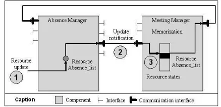
When considering the Shared-diary component, figure 4 shows an example of communication interfaces which are used in order to manage the Absence_list resource. This resource is an instance attribute whose value repre-sents day of absence for a given person. It is shared by the Absence-Manager and Meeting-Manager generated-components. When the Absence_list resource is updated by the Absence-Manager component (1), a notification is send to the Meeting-Manager component (2). Next, the
Meeting-Manager component memorizes the new value
(3).
Figure 4. Example of communication interfaces
The second type of interfaces (i.e. synchronization-access interfaces) allows the component to synchronize access to a shared resource. These are:
1) An interface defining required services permitting the component to acquire, from components sharing a resource, an authorization to update this one. 2) An interface defining provided services allowing the
component to release rights to update a shared re-source. These services are requested by components sharing a resource with the component providing this interface.
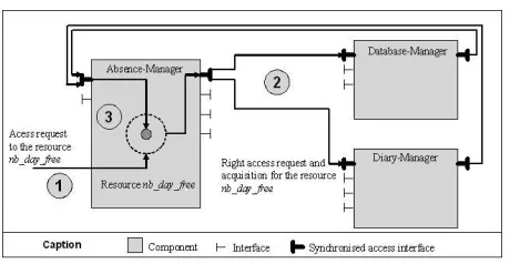
Figure 5 shows an example of synchronization-access interface which is used to manage the nb_day_free re-source, related to the Shared-Diary component. This resource is an instance attribute whose value represents the number of free days for a given person. It is shared by the Absence-Manager, Database-Manager and
Diary-Manager components. First, Absence-Diary-Manager
compo-nent which needs to update the nb_day_free resource (1) asks a right-access to the other component which shared this resource (e.g. DataBase-Manager and
Diary-Manager) (2). When Absence-Manager component
Figure 5. Example of synchronized access interfaces
The implementation of the communication and synchronization-access interfaces is realized through the instrumentation of the generated-component object-oriented source-code (See Sect. V).
D. Integration of the transformation result
The last step of our process is the integration, in the subjacent application, of the component restructuring result obtained during the previous stages. It consists in connecting the new generated-components with the other application components while ensuring that the com-ponent transformation is achieved in a transparent way compared to the application components. So, integration requires to satisfy the following properties:
• Security feature: the application components should not be able to access, after the component trans-formation, to other services than those provided by the component before its transformation. In fact, all new interfaces (i.e. created by our process) must not be accessed by application components, except those created by transformation. For example, all compo-nents must not access to services allowing to modify a shared resource state (i.e. only components which share this resource can access to related services). • Distribution feature: the new generated-components
can be accessed and handled as separate entities. For example, it would be possible to specify a deployment configuration by a direct designation of the generated-components.
Our solution to guarantee these properties consists in wrapping components generated by fragmentation into a new composite-component (see Fig. 6). This new compo-nent allows us to mask services created by the process. Moreover, it provides additional interfaces allowing it to manipulate its sub-components. For example, these interfaces aim at realizing independent deployment of each sub-component.
Furthermore, we define a composite-component as pro-viding facilities for possible functional adaptations. This is done via a second non-functional interface integrated to the composite-component interface set. This interface allows the administrator to set a collection of configurable properties. For example, the two following properties al-low the administrator to customize sub-component access:
• Sub-component encapsulation: This property refers to the visibility and the accessibility of sub-components considering other application compo-nents. A generated composite-component can be specified as (1) "white-box", which means that com-posite structure is visible and sub-components are directly accessible, (2) "black-box", which imposes sub-components to be neither visibles nor accessibles by other application components or (3) "mix-box", which means that some sub-components, not all, can be accessibles directly by the other application components.
• Internal access: This property permits us to specify how a component can be accessed by other sub-components. This can be configured either via the composite-component or via a direct reference to a sub-component.
Access through the composite allows us to pre-pare a future functional adaptation. In fact, as all service-invokes exchanged between sub-components are analysed by the composite, post or pre-conditions may be set up easily.
IV. FROM A CENTRALIZED COMPOSITE-COMPONENT
TO A DISTRIBUTED COMPOSITE-COMPONENT
The fragmentation process realized during the first phase of our approach allows us to generate a new composite-component. However, this result cannot be dis-tributed on several hosts because all sub-components use local binding. As many resources or services cannot be accessed using direct references because they are provided by remote components (i.e. sub-components are intercon-nected through bindings which can be local or remote references between provided and required interfaces), we need to ensure communications between local and remote components. In order to create distributed components, first, we need to specify the new component distribution (i.e. to specify sites for each component). This speci-fication is realized through ADL generation (see Sect. III-A). Then, the component structure is automatically updated (i.e. creation of new interfaces and components dedicated to the distribution management) and component code is instrumented in order to ensure coherence (i.e. a component may access to all resources or services needed during its execution).
Figure 7. Component distribution model
A. Distributed composite-component
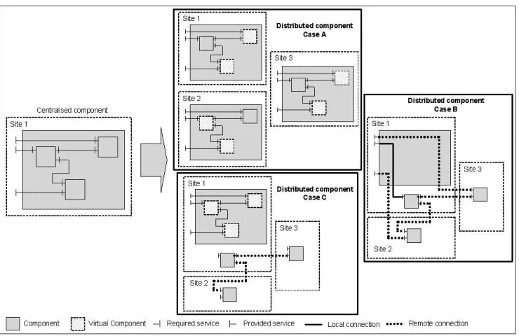
A distributed component is a component whose sub-components may be deployed on different hosts. We tinguish three solutions which can be used to create a dis-tributed component. The first one (see Fig. 8 Case B) con-sists in deploying sub-components on different hosts and the composite on only one. In this case, the composite-component instance contains only connectors which are used to transfer messages from provided composite ports (or interfaces) to sub-component ports (or interfaces) which may be provided by a local or a remote host (i.e. export binding). Moreover, sub-components are connected together through direct binding which may be local or remote ones. This strategy implies that sub-components may be accessible by a direct way. Moreover, the visibility of the internal composite structure is blurred. The second solution (see Fig. 8 Case C) consists in the use of virtual components within the composite. Virtual components are used in order to access a remote component (see below). This strategy allows us to improve composite structure visibility. The last solution (see Fig. 8 Case A) consists in the creation of a composite-component into every host on which a part of the component is deployed. This solution allows us to preserve a strong encapsulation of the created components. A composite-component instance is loaded on each host which contains a part of this component (i.e. at least one sub-component). Nevertheless, the entire composite-component is not instancied on each host. In fact, different copies of the composite-component are instancied. Each instance is composed of a set of local components and a set of virtual components.
1) Local components: Local component means real
component (i.e. sub-component) of the composite-component. They are generated during the fragmentation step of the first transformation. Each component is instan-cied in only one host (i.e. those which are specified by the administrator during the specification step).
2) Virtual components:
a) Virtual component structure: A virtual
compo-nent provides the same interfaces than those of the remote component, however implementation (i.e. service code) is different. In fact, functional code is replaced by controller code which allows it to invoke remote services. Two
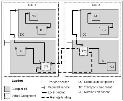
interfaces are added to this virtual component (Fig. 9): one is required and allows the component to send messages to the remote component and the other one is provided and allows the component to receive messages from the remote component. These two interfaces ensure remote communications. Bindings between virtual components are created using architecture description analysis (i.e. ADL analysis). For example, when a local component C1 deployed on site 1 is bound to a remote compo-nent C2 deployed on site 2 (i.e. a required interface of the component C1 is linked to a provided interface of the component C2), we create two links: one from the provided interface of the component C’2 (i.e. virtual component of C2 on site 1) to the required interface of the component C’1 (i.e. virtual component of C1 on site 2) and the other one from the provided interface of the component C’1 to the required interface of the component C’2. Communications between C’1 and C’2 components are realized through these two new interfaces whose services use the distribution components (see Sect. IV-B).
Figure 9. Example of component distribution
b) Virtual component behavior: A virtual
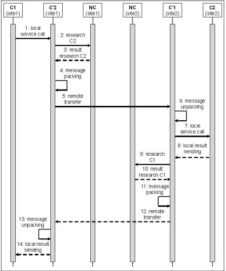
Figure 10. UML2 Sequence Diagram of the distribution process between two components
B. Distribution components
A new controller component called distribution com-ponent which allows generated-comcom-ponents to ensure remote communications is added to our model. It is composed of two sub-components:
• A transport component: it allows virtual components to realize remote communications (i.e. services pro-vided by the transport component allow the com-ponent to pack and unpack messages which are exchanged between local and remote components, and set up connections through network protocols). • A naming component: it allows the transport
nent to find the host address on which local compo-nent services are instancied (i.e. services provided by the naming component allow a component to search and locate remote components).
As we explained previously, different component in-stances are loaded on deployment hosts. As a copy of the composite-component is created on each site, non-functional services (i.e. service allowing the composite to manage its content, service allowing the composite to manage bindings between sub-components, service allowing the composite to manage component life cycle, etc.) are duplicated. So, we need to ensure communication and coherence between component instances at the control scale in order to preserve software component integrity. For example, when the composite-component starts, the other instances loaded on the remote hosts have to start their own component version.
V. SOURCE-CODE INSTRUMENTATION
In order to preserve coherence of the generated-components, we defined specific interfaces which aim at ensuring a coherent state among generated-components. The state of a component consists of the set of its resource values. As a resource can be duplicated in several component implementations, we need to preserve a co-herent state of these resources in all components sharing them. Thus, the coherence-interface role is to preserve the coherence of the shared-resource state. This is realized through source-code instrumentation permitting to imple-ment notification and synchronization mechanisms.
A. Source-code instrumentation for resource-update no-tification
After updating a resource in one generated-component, the new state of this resource must be communicated to the other generated-components. Thus, it is necessary to determine how and where this resource is updated within the component source-code and next, we need to instrument this code by adding notification instructions from one component to the others.
The first issue for the source-code notification in-strumentation is how a resource can be updated. This operation can be realized by using a direct or an indirect reference to this one and by using an update-instruction. For example, in the case of Java, where a resource can be an attribute, this last can be updated directly or using a reference to this one. The last case appears when an instance is used as a method argument2.
The second issue is how to distinguish update instructions from those which are not. In fact, primitive-resource updates are realized using affectation instructions whereas resources which are object instances, are updated using method calls. So, in order to detect resource-updates, we need to instrument source-code by saving the state-value of a resource before its manipulation. Then, this resource-state value is compared with that obtained after the instruction execution. If these two state-values (re-spectively before and after a resource-update instruction) are different, a notification to the other components which shared this resource, is needed.
The last issue consists in determining when we have to send a resource-update notification. In fact, the no-tification sending time depends on the moment when components which receive the message take into account this notification. As all resources update instructions are gathered in the same critical-section blocking for the other components (see V-B), it is useless to notify all resources updates because only the last one is taken into account by the other components. So, the resource update notification must be sent just before the critical-section end.
To illustrate these issues, reconsider the shared-diary example. The class implementing this component defines two attributes named absence_Dates_list and right_max
2In Java, primitive attributes (e.g. integer, real numbers, char, boolean
which represent respectively the absence dates for peo-ple considered by the shared-diary and the number of absence days which a person still has right. These attributes are considered as shared-resources. In fact, the add_new_absence_day and consult_remaining_days methods use both these attributes. In fact, after the structure transformation of the Shared-Diary compo-nent, these methods are defined respectively in two separate generated-components: Absence-Manager and
Right-Manager. So, when a service provided by one
of these two components starts a critical-section, the
absence_Dates_list and right_max state-values are saved.
Next, just before the critical-section stop, the new values are compared with the saved ones. When a modification is detected, an update-notification related to the resource whose state-value has changed, must be sent to the other components which shared this resource.
B. Source-code instrumentation for resource-access syn-chronization
Resource-access synchronization is the second condi-tion to ensure the generated-component coherence and thus, to guaranty the correctness of the results which are returned by concurrent service executions. In fact, the resource-access synchronization consists in the ban of all simultaneous accesses to a same resource. The solution lies on the placement of resource-access instructions inside critical-sections implemented using semaphores.
1) Criticsection setting: Criticsections which
al-low components to ban concurrent access are setting up through locks within an entire service. So, we define a service critical-section as the code-fraction which includes all write or read resource-instructions. In fact, locks are setting up between the first and the last resource-access instructions with regard to the entire service.
In order to determine the possible critical-section starts and ends, we use static code-analysis. However, in order to favor parallelism, the critical-section size has to be the shortest as possible. So, the effective set-up of a critical-section is realized dynamically (i.e. during the service runtime). Indeed, the critical-section set-up requires two steps (see Fig. 11):
• Critical-section entry-point
In order to set up critical-section, first, we search all the possible entry-points. For that purpose, it is necessary to parse the method source-code in order to detect resource-access points (i.e. instructions). Then, code is instrumented before each resource-access to allow service to put a lock dynamically. In fact, critical-sections have to be started just before the first resource-access inside a service. So, when a critical-section entry-point is dynamically detected, the service checks the lock state-value. If the lock is not activated, then the service has to start a critical-section. In this case, the service has to request an authorization to start a critical-section. When it ob-tain this authorization, it can start its critical-section by locking resource-access for the other services.
In the case of the lock is yet activated, the service is inside a critical-section. So, it can continue its execution because all resources are locked for the other services.
• Critical-section exit-point
The second operation which we have to realize in order to set up critical-section, consists in detecting all the possible critical-section exit-points. For that purpose, it is necessary to determine all resource-update instructions. Then, we build the execution stream-graph of the entire service. We extract a sub-graph whose nodes represent the resource-update in-structions or the first inin-structions which are executed just after a fork within the stream-graph. Finally, we analyze it in order to determine the critical-section exit-points. Our algorithm is presented below.
For each path For every node N
P = {path p / p starts from this node, its end is an exit-point and it contains a resource-access point} If P=Then
add(N,List of possible critical-section exit points);
EndIf EndFor EndFor
add(N,L): add the node N inside the list L.
2) Authorization-acquisition for critical-section start-ing: As we explained previously, critical-section starting
is managed through the acquisition of an authorization by the service. In fact, this authorization is materialized by the acquisition of what we call "token". Our approach requires the use of a stack for every component and a sequencer 3. Each element of the stack contains an
identifier of the service which asks a token and the set of resources concerned. The stack elements are ordered according to their identifier.
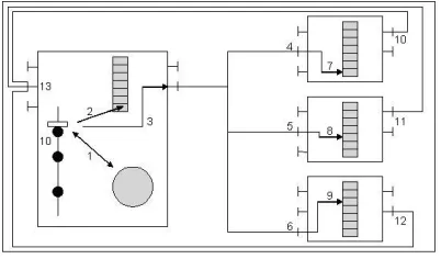
The process for getting a token is described in figure 12: when a service wants to start a critical-section, it asks the sequencer for an identifier which allows it to order requests (1). Then, it puts this identifier and the set of needed resources into its stack (2). So, it sends its request to the other components by supplying these data (e.g. identifier and set of needed resources) (3). When a component receives its request (4/5/6), it puts that in its stack according to the number which was supplied by the sequencer (7/8/9). Then, it sends back a delivery notification (10/11/12). A component gets the token only when there is no element of the stack before it which contains a resource included in its set and when it receives a delivery notification from all other components sharing the resource (13). When the service which has the token aborts a critical-section, this last one is deleted from the stack.
3) Critical-section authorization transfer: When a
ser-vice calls another one, the critical-section authorization must be transfered to the called service. So, a service needs to send the token from a method to the other one.
3Software entity used to deliver identifiers which aim at ordering
Figure 6. Integration of component transformation result
Figure 8. Transformation from a centralized component to a distributed one
Figure 12. Right-access acquisition mechanisms
As two different methods can have the same signature, every method (i.e. service) has to know in which context they are called. Thus, methods have to send an identifier of their entire service.
For example, if there are two components C1 and C2 which provide respectively the services A and B, service A of the component C1 calls the service B of the component C2, it is necessary that the service B knows that it is called within the context of service A. Indeed, if service A locks the needed resources before calling the service B, when the service B is running, it must know that it has the token (i.e. in order to release the lock) because the service B is included in service A.
In order to ensure the token transfer, we introduce a new optional parameter for each method (i.e. service). Thus, it allows services to determine in which context they are called. When this parameter is indicated, the service is called within the context of a specified service. Otherwise, if this parameter is not indicated, the method is the first which is called inside the entire service. However, one of the adaptation constraints is that we cannot modify component interfaces because they can be used by other application components. Thus, new interfaces which contain the internal method signatures (i.e. signatures of services which are called by another) should be created.
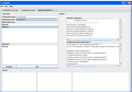
VI. SCORPIO:A SOFTWARE COMPONENT ADAPTATION TOOL
We implemented our transformation process through a tool called SCORPIO (Software COmponent stRuctural adaPtatIOn). Scorpio is an tool which allows the appli-cation administrator to transform a monolithic central-ized component into a distributed composite-component, taking into account execution context. The tool requires source-code availability of the initial component and the result is the component source-code of the transformation result.
Scorpio has been implemented using the Fractal com-ponent model [6] and its Java implementation called Julia [7] developed by the INRIA4. Many deciding factors have
motivated the choice of Fractal. In fact, this model is
4The French National Institute for Research in Computer Science and
Control. http://www.inria.fr/
a hierarchical component model quite close to UML2 model [8] with the only difference that port concept is not defined. In this model, provided and required services are structured in interfaces which are used by components when they communicate with each other. Each server in-terface gives access to a set of operations. And, each client interface defines a set of operations that the component may invoke. To create a Fractal component, using the Java implementation, it is necessary to specify a single class which implements all services (i.e. methods) specified by the corresponding component interfaces. Only primitive components can be implemented.
SCORPIO provides the software component structural adaptation service. In fact, this service allows the ap-plication administrator to realize the transformation of a monolithic centralized component into a distributed composite-one. First, the administrator has to specify the directory path where component source-code is available and the architecture description file. Then, he has to realize the specification stage of the component transfor-mation (see Fig. 13). This operation is directed by the tool which propose to create new sub-components according to the available services (i.e. interfaces) and execution context. In fact, the new component must be specified through their name, their provided services and their deployment hosts. Source-code corresponding to the new created entities is automatically generated, then source-code files are compiled using the compilation environment and finally the new obtained component is deployed on the available infrastructure according to the specification. In fact, each binary code is moved to the corresponding host mentioned in the specification script. The remote deployment is realized by deployment machines installed on every node of the distributed infrastructure. When a deployment machine receives the binary code correspond-ing to a component, it has to deploy it. So, when all remote generated sub-components are deployed on their corresponding host, the distributed composite-component generated through our transformation process can be started and its provided services can be invoked.
We note that we experimented our tool using the
shared-diary component described in this paper. In fact,
the shared-diary component, such as it was designed, cannot be deployed entirety in a constrain-resource device (e.g. PDA). This is due to its memory size which appears insufficient. So, we have to adapt the component structure in order to deploy it on this device. Using Scorpio, allow-ing us to realize the structural adaptation, we created a component-composite starting from the initial monolithic component. This component-composite was automatically deployed on several accessible sites through a wireless network.
VII. RELATED WORK
Figure 13. SCORPIO: a software component adaptation tool (screenshot)
focuses on works which topic is restructuring program codes and more particular object-oriented ones.
A. Approach goal: software component adaptation
Many approaches have been proposed in the literature in order to adapt software component-based applications. These ones can be classified according to different criteria as it is described bellow5:
Adaptation needs: Software component-based appli-cation can be adapted in order to improve performances (e.g. [9]), design or implementation (e.g. [10], [11]) (i.e. perfective adaptation). Also, these applications can be adapted to better taking into account of the deployment environment (e.g. [12]) (i.e. adaptive adaptation). Another adaptation need is the evolution of the application func-tionalities [13] (i.e. adding new services).
Concerning our approach, it can be classified as adaptive adaptation. In fact, it aims, for example, at taking into account component deployment environment and conse-quently to adapt this one by restructuring it.
Adaptation actors: An adaptation actor is a physical
or software entity which is able to start, to stop, to modify, to cancel or to supervise an adaptation phase. We distinguish four adaptation actors: the programmers (e.g. [14]) (i.e. which defines rules and mechanisms allowing the adaptation of the application), the administrator (e.g. [13]) (i.e. he can start an adaptation phase), the adapter
5List of works cited in this section is not exhaustive. Works referenced
here are given as examples among existing ones.
(e.g. [13]) (i.e. tool which realizes all tasks contained in an adaptation process), the software (e.g. [15]) (i.e. it undergoes an adaptation process, however, it can start and realize itself its adaptation).
Concerning our approach, adaptation actors is an admin-istrator which specifies and starts the structural adaptation process.
Adaptation target: Adaptation can concern components
(e.g. [16]), elements which compose them (e.g. [17]) (e.g. interfaces, ports) or the application configuration (e.g. [18], [16]) (e.g. connectors).
Our approach focuses on software component adaptation.
Adaptation moment: An adaptation process can be
acti-vated either before the considered application deployment (e.g. [13]), during its deployment (e.g. [12]) or during its execution (e.g. [9]).
According to the activation moments, adaptation can be realized in a static way (e.g. [13]) or in dynamic one (e.g. [9]).
Our approach may be realized before application deploy-ment. Also, it can be used when a component is loaded. Actually, our approach is realized in a static way.
Superimposi-tion (e.g. [20]) is an alternative technique where the idea behind is that the entire functionality of a component should be superimposed by certain behavior. For more details about adaptation techniques see [21].
Our adaptation approach can be considered as "black-box" considering adaptation administrator which does not need to manipulate component source-code. But it can be considered, also, as "white-box" when considering the adaptation process which needs component source-code.
Adaptation facet: Adaptation approach can be clas-sified as service-focus or structure-focus. To our knowl-edge, all existing approaches are service focus, except perfective adaptation approaches (e.g. [10], [11]). These lasts propose to replace a component implementation with another. Considering this criterion, our approach is structure-focus.
B. Used technique: software component refactoring
Our approach is based on component decomposition and refactoring. Refactoring is a technique used for re-structuring an existing body of code, altering its internal structure without changing its external behavior [22]. Generally, refactoring is used to make the code simpler in order to include or understand it more easily [23]. It is also used to find potential bugs or errors more quickly. It makes it possible to eliminate duplicated code. The goal of this technique is to reorganize classes, variables and methods in a new hierarchy in order to facilitate its future adaptation or extension [10]. Its use increases the program quality (e.g. reusability). However, concerning our approach, we do not aim at improving quality of the component source-code but rather at modifying their structure, without changing their behavior, in order to adapt them to their execution context (e.g. adaptation for flexible component deployment). Other approaches, close to our, propose the concept of breakable objects as building blocks for flexible application architectures (e.g. [24]) or they introduce distribution mechanisms into centralized applications (e.g. [25]). For more details about adaptation techniques see [21].
VIII. CONCLUSION AND FUTURE WORKS
We presented in this article an approach allowing us to create distributed components from monolithic ones. Our proposal is based on a new adaptation technique which aims at reorganizing the software component structure us-ing code refactorus-ing. In fact, as we explained, component deployment and execution are linked to its structure. So, we propose to use this approach in order to fragment existent components and generate new components which can be distributed on several hosts. This approach is implemented and a prototype has been developed using the Julia [7] software component framework which is the Java implementation of the Fractal component model [6]. Our approach needs source code analysis and instrumen-tation. It does not consider run-time adaptation problems. However, it is generic enough to be applied to dynamic
adaptation. Nevertheless, concerning this possibility, it is necessary to define, in addition to the presented process, mechanisms for the dynamicity management (e.g. dis-connection, dis-connection, interception of the invocations of services, service recovery, etc). Thus, this way constitutes one direction of our future work.
As we noted it before, the main application of our approach consist in realizing a flexible deployment of software components. A future work may consist in the deployment process automation according to the execu-tion context.
REFERENCES
[1] G. T. Heineman and W. T. Councill, Eds., Component-based software engineering: putting the pieces together. Boston, MA, USA: Addison-Wesley Longman Publishing Co., Inc., 2001.
[2] C. Szyperski, Component software: beyond object-oriented programming. New York, NY, USA: ACM Press/Addison-Wesley Publishing Co., 1998.
[3] S. A. Hissam, R. C. Seacord, and G. A. Lewis, “Building systems from commercial components,” in ICSE ’02: Pro-ceedings of the 24th International Conference on Software Engineering. New York, NY, USA: ACM Press, 2002, pp. 679–680.
[4] A.-D. Seriai, G. Bastide, and M. Oussalah, “Transforma-tion of centralized software components into distributed ones by code refactoring,” in Proc. of the 6th International Conference on Distributed Applications and Interoperable Systems, Bologna, Italy, June 2006.
[5] G. Bastide, A.-D. Seriai, and M. Oussalah, “Adapting soft-ware components by structure fragmentation,” in Proc. of the 21st Annual ACM Symposium on Applied Computing, Dijon, France, April 2006.
[6] E. Bruneton, T. Coupaye, M. Leclercq, V. Quéma, and J.-B. Stefani, “An open component model and its support in java,” in Proceedings of the International Symposium on Component-based Software Engineering (CBSE’2003), Edinburgh, Scotland, May 2004.
[7] E. Bruneton, “Julia tutorial:
http://fractal.objectweb.org/tutorials/julia/,” 2003. [Online]. Available: http://fractal.objectweb.org/tutorials/julia/ [8] H.-E. Eriksson, UML 2 Toolkit. Wiley edition, 2003. [9] A. Ketfi, N. Belkhatir, and P. Cunin, “Automatic adaptation
of component-based software: Issues and experiences,” in PDPTA’02, 2002.
[10] B. Foote and W. F. Opdyke, “Lifecycle and Refactoring Patterns That Supports Evolution and Reuse,” 1995, pp. 239–258. [Online]. Available: citeseer.ist.psu.edu/foote95life.html
[11] E. Gamma, R. Helm, R. Johnson, and J. Vlissides, Design Patterns: Elements of Reusable Object-Oriented Software. Addison-Wesley Professional, 1995.
[12] N. L. Sommer and F. Guidec, “A contract-based approach of resource-constrained software deployment,” in CD ’02: Proceedings of the IFIP/ACM Working Conference on Component Deployment. London, UK: Springer-Verlag, 2002, pp. 15–30.
[13] R. Keller and U. Hölzle, “Binary component adaptation,” Lecture Notes in Computer Science, vol. 1445, pp. 307–329, 1998. [Online]. Available: citeseer.ist.psu.edu/keller98binary.html
[15] S. A. Dobson, “Component-oriented approaches to context-aware computing.” in ECOOP Workshops, 2004, pp. 84–93.
[16] E. P. A. Brogi, C. Canal, “Behavioural types and com-ponent adaptation,” in 10th International Conference on Algebraic Methodology and Software Technology, 2004, pp. 42–56.
[17] D. Balek, “Connectors in software architec-tures,” Ph.D. dissertation, Charles University, Czech Republic, 2002. [Online]. Available: cite-seer.ist.psu.edu/balek02connectors.html
[18] T. Batista and N. Rodriguez, “Dynamic reconfiguration of component-based applications,” in PDSE ’00: Proceedings of the International Symposium on Software Engineering for Parallel and Distributed Systems. Washington, DC, USA: IEEE Computer Society, 2000, p. 32.
[19] B. Kucuk, M. Alpdemir, and R. Zobel, “Customizable adapters for blackbox components,” 1998. [Online]. Avail-able: citeseer.ist.psu.edu/article/kucuk98customizable.html [20] J. Bosch, “Superimposition: A component adaptation technique,” Information and Software Technology, vol. 41, no. 5, pp. 257–273, 25 March 1999. [Online]. Available: citeseer.ist.psu.edu/281749.html
[21] G. Heineman and H. Ohlenbusch, “An evaluation of component adaptation techniques,” Department of Com-puter Science, Worcester Polytechnic Institute, Tech. Rep. WPI-CS-TR-98-20, February 1999. [Online]. Available: citeseer.ist.psu.edu/article/heineman99evaluation.html [22] T. Mens and T. Tourwe, “A survey of software refactoring,”
in IEEE Transactions on Software Engineering, ser. 2, vol. V. 30, 2004, pp. 126–139.
[23] M. Fowler, K. Beck, J. Brant, W. Opdyke, and D. Roberts, Refactoring: Improving the Design of Existing Code. Addison-Wesley Object Technology Series, 1999. [24] V. Jamwal and S. Iyer, “Bobs: breakable objects,” in
OOP-SLA ’05: Companion to the 20th annual ACM SIGPLAN conference on Object-oriented programming, systems, lan-guages, and applications. New York, NY, USA: ACM Press, 2005, pp. 98–99.
[25] E. Tilevich and Y. Smaragdakis, “Nrmi: Natural and efficient middleware,” 2003. [Online]. Available: citeseer.ist.psu.edu/tilevich03nrmi.html
Abdelhak Seriai is currently an assistant professor in the computer science department of the Ecole des Mines de Douai (France). He obtained an engineering degree in computer sci-ence in 1994 from Annaba university (Algeria) and a PhD in computer science in 2001 from Nantes university (France). His research interests concern object-oriented and software component technologies.
Gautier Bastide is a PhD student at the department of Computer Science of the Ecole des Mines de Douai. His research interests are in component-based software engineering. The topic of his PhD thesis is software component adaptation in ubiquitous and mobile environments.