Shivalinga et al. World Journal of Engineering Research and Technology
TRIBOLOGICAL BEHAVIOR OF AL-MG ALLOY REINFORCED
WITH MICRO TITANIUM AND BORON CARBIDE PARTICULATE
HYBRID METAL MATRIX COMPOSITES
Madegowda B.1, Shivalinga S.*2, Dr. Vidyasagar. H. N.3 Dr. H. K. Shivanand4, Bylappa B. K.5 and Janardhan C. V.6
3,4
Associate Professor, Department of Mechanical Engineering, UVCE, Bangalore 560001.
2,5
ME Scholar, Department of Mechanical Engineering, UVCE, Bangalore 560001.
1
Ph. D. Scholar, Department of Mechanical Engineering, UVCE, Bangalore 560001.
6
BE Scholar. Department of Mechanical Engineering, EWIT, Bangalore 560091.
Article Received on 20/09/2017 Article Revised on 11/10/2017 Article Accepted on 01/11/2017
ABSTRACT
In the present investigation on tribological behavior of Al-Mg alloy
reinforced with micro Ti and B4C particulates hybrid metal matrix.
The composites were fabricated by using the stir casting technics by
varying weight percentage of reinforcements i.e. [for sample 1 (A-Mg
100%), sample 2 (Al-Mg 94%+Ti 5%+B4C 1%), sample 3 (Al-Mg 93% + Ti 5%+B4C 2%),
Sample 4 (Al-Mg 92%+Ti 5%+B4C 3%)] the dry sliding wear test carried out of pin on disc
wear testing machine. Aluminium matrix composites are widely used in Engineering
applications due to their good physical and mechanical properties such as high strength to
weight ratio, good ductility, corrosion resistance, availability and low cost. The application of
aluminium alloys have been restricted because of soft and for their poor wear resistance. This
problem is overcome by addition of reinforcements into the metallic matrix. After
reinforcement metal matrix composites have the enhanced properties such as stiffness,
specific strength, wear, creep and fatigue properties compared to unreinforced alloys.
Aluminium matrix composites are used in engineering applications such as aircraft,
aerospace, automobiles and various other fields. In the automobile sector aluminium based
metal matrix composites are used for making of automotive Engine components such as
World Journal of Engineering Research and Technology
WJERT
www.wjert.org
SJIF Impact Factor: 4.326*Corresponding Author
Shivalinga S.
ME Scholar, Department of
Mechanical Engineering,
vehicles bodies, cylinder blocks, pistons, pistons rings, cylinder blocks, cylinder liners and
brake drum. Wear is one of the serious problems which need further scrupulous solutions.
KEYWORDS: Al-Mg, B4C, Ti, stir casting, tribological, dry sliding wear, pin on disc machine.
INTRODUCTION
Discontinuous reinforced aluminium metal matrix composites (DRAMMC’s) are a class of
composite materials which are having desirable properties, which include low density, high
specific stiffness, high specific strength, controlled co-efficient of thermal expansion,
increased fatigue resistance and superior dimensional stability at elevated temperatures
etc.[1,2,3] Aluminium matrix composites are fast emerging as engineering materials and
exhibits better mechanical and physical properties than common metals and alloys. They are
gaining significant acceptance because of higher specific strength, specific modulus and good
wear resistance as compared to ordinary unreinforced alloy. Lightweight aluminium metal
matrix composite materials hold potential requisite for modern tribological applications due
to its inherent and better wear resistant properties over monolithic metallic materials. Metal
matrix composites are advanced materials, which combine metallic matrix with a hard
ceramic reinforcement such as SiC, B4C, TiC, Al2O3 or soft reinforcement to produce
composite materials.[4] Aluminium alloy and its alloy elements such as Magnesium, Copper
etc. reinforced with ceramics due to their exponential combination properties. These are used
in ship and submarine building, transportation, heavy vehicles, pressure vessels, bridges,
buildings, automobile and aircraft parts and braking systems.[5] The
aluminium-magnesium-silicon carbide composites reduces the fuel consumption and improves the efficiency due
their light weight. The desire in the engineering community to develop a new material with
greater wear resistance and better mechanical properties, without much compromising on the
strength to weight ratio led to the development of metal matrix composites.[6-10] Aluminium is
one of the most commonly used metal matrixes for production of Metal matrix composites.
Metal matrix composites exhibits superior wear resistance owing tribological applications.
These include pistons and cylinder liners in automotive engines, brake discs/drums in railway
vehicles and in automobiles.[11-14] However, cost still remains a major barrier in designing
aluminium composite components for wider applications in automotive industries along with
MATERIALS AND EXPERIMENTEL DETAILS Material
The material used in this study is Aluminium- Magnesium alloy, having the chemical
composition as shown in Table-
Component Weight%
Silicon 0.4
Iron 0.4
Copper 0.1
Manganese 0.4-1.0 Magnesium 4.0-4.9
Zinc 0.25
Titanium 0.15 Chromium 0.05-0.25 Aluminium Balance
Boron Carbide (B4C)
Boron carbide, (B4C), crystalline compound of boron and carbon. It is an extremely hard,
synthetically produced material that is used in abrasive and wear-resistant products, in
lightweight composite materials, and in control rods for nuclear power generation. Boron
Carbide (B4C) particle of size 250 micron was used as the reinforcing material.
Boron carbide properties
Density 2.52gcc
Melting point 24450C
Young's Modulus 450-470GPa
Figure: Boron Carbide powder. Titanium Powder
Titanium powders vary in terms of size and purity and can alloyed with several other kinds of
other metal additives producing powders such as titanium iron alloy and titanium aluminium
machinery, and components are used extensively in the medical industry, being used in heart
pacemakers and cranial shells. More recently it has seen a rise in demand due to the rise in
popularity of 3D printing and the ideal properties of the material.
Properties of Titanium
Density- 4.506gcc
Melting point -16680C
Young's Modulus -116GPa
Color – Gray
Fabrications of Composites
Furnace and heated up to 650o .The metal was stirred with the help of mechanical stirrer to
form a fine vortex. The boron carbide powder (250 micron) along with Ti powder is
preheated at about 2500C and it is added with the molten metal. The molten mixture is then
stirred continuously at 320rev/min. The molten liquid metal is poured into the permanent
mould which has preheated at 250oC. By varying the weight percentage of the boron carbide
(1%, 2%, 3%,) the material has been fabricated.
Figure 3.1: Line diagram of stir casting.
Steps Involved in casting process
First of all, 1200gm of commercially available aluminium-magnesium was melted in a resistance heated muffle furnace and casted in a clay graphite crucible. For this the melt
temperature was raised to 7500C.
Before mixing Titanium and B4C particulate preheating at 5000c temperature
Titanium and Boron carbide powders were mixed in the red hot liquid Al-Mg kept in the
stirred such all the constituent material get mixed properly with the base metal that is
Al-Mg.
Later the red hot liquid mixture is poured in to ASTM casting dies and allowed it for
solidification for ½hour.
Figure a: The Electric furnace.
Figure b: The Graphite Crucible.
Figure d: The crucible inside metal.
Figure e: The crucible temperature sets.
Figure f: The pre heat die.
Figure h: Pouring of molten metal into mould box.
Figure i: opening die Removal of composite from mould box.
Figure 6.2: steps involved casting process. Experimental Procedure
Wear Test Procedure
Immediately prior to testing, and prior to measuring or weighing, clean and dry the
specimens. Take care to remove all dirt and foreign matter from the specimens. Use
non-chlorinated, non-film-forming cleaning agents and solvents. Dry materials with open
grains to remove all traces of the cleaning fluids that may be entrapped in the
material. Steel (ferromagnetic) specimens having residual magnetism should be
Measure appropriate specimen dimensions to the nearest 2.5μm or weigh the specimens
to the nearest 0.001g
Insert the disk securely in the holding device so that the disk is fixed perpendicular
(+/-1°) to the axis of the resolution.
Insert the pin specimen securely in its holder and, if necessary, adjust so that the
specimen is perpendicular (+/-1°) to the disk surface when in contact, in order to
maintain the necessary contact conditions.
Add the proper mass to the system lever or bale to develop the selected force
pressing the pin against the disk.[17]
Start the motor and adjust the speed to the desired value while holding the pin specimen
out of contact with the disk. Stop the motor.
Set the revolution counter (or equivalent) to the desired number of revolutions.
Begin the test with the specimens in contact under load. The test is stopped when the
desired number of revolutions is achieved. Tests should not be interrupted or restarted.
Remove the specimens and clean off any loose wear debris. Note the existence of features
on or near the wear scar such as: protrusions, displaced metal, discoloration, micro
cracking, or spotting.[18]
Remeasure the specimen dimensions to the nearest 2.5μm or reweigh the specimens to the
nearest 0.001g, as appropriate, spotting.
Repeat the test with additional specimens to obtain sufficient data for statistically
significant results.
The data of pin height loss was used to calculate the wear rates of the cast hybrid composites
given by the formula:
Where
R= crack radius of disc in m.
N= speed of disc plate in rev/min.
Figure 4.1: Wear Testing Equipment.
Figure 4.2: Wear Test Specimen. RESULTS AND DISCUSSIONS
The wear test was conducted using a pin on disc test machine in accordance with ASTM
standard G99-05.The following wear results are obtained for
Four different applied loads of 20N, 30N, 40N & 50N for a total sliding distance of
3000m at a constant sliding speed of 0.84 m/s.
Four different sliding velocities of 0.42 m/sec, 0.84 m/sec, 1.26 m/sec & 1.6 m/sec,
against normal loads of 20 N for constant 3000m sliding distance.
Four different sliding of 1000m, 2000m, 3000m & 4000m at constant sliding velocity
Co-efficient of Friction Effect of Load
Figure 5.1: Indicate Coefficient of Friction of Both A1-Mg alloy and its Composites Decreases with Increased Loads.
Friction coefficient is the ratio between the force developed and the applied force. Friction
values for matrix and composite material were in expected range for light metals in dry
sliding conditions, with remark that composite material, for the applied load range, showed
slightly higher values comparing to the matrix material.[21] Wear resistance of the composites
increases with increase in percentage of fly ash.[22] The friction coefficient of composites with
coarse fly ash particles is higher compared to those of fine particles. The friction coefficient
of fly ash particles exhibits increasing trend with increase in particle size. Higher coefficients
of friction in the case of composites containing hard particles may be due to the formation of
tribofilm at the interface between pin and disk. Composites decreases with increase in fly ash.
The Coefficient of Friction of unreinforced Al-Mg & reinforced Al-Mg composite were
studied for four applied loads 20N, 30N, 40N & 50 N and five different composite specimens
with varying weight percentage of particle reinforcement. It is found that the coefficient of
friction is maximum at a load of 20 N for both the matrix alloy Al-Mg and its composites.
However the boron carbide (3%) weight fraction reinforced composite possesses the lowest
coefficient of friction at this load and the friction coefficients are reduced by 30% in the
range of 0.3–0.42 it can be noticed in graph. The coefficient of friction of both Al-Mg alloy
Wear Rate Effect of Load
Applied load affects the wear rate of alloy and composites significantly and is the most
dominating factor controlling the wear behavior at constant speed, the wear rate of the Al-Mg
composites and the matrix increases with increase in load. Similar observations were reported
in the Influence of Particle Size on Dry Sliding Friction and Wear Behavior of Fly Ash
Particle – Reinforced A380 Al Matrix Composites.[23] The results indicate that the volume
Content of particulates boron carbide reinforcement has a marked effect on the wear rate. The
wear rate of the composite specimens decrease with increasing weight percentage of boron
carbide particulate reinforcement.
Figure 5.2(a) Indicate That the Wear Rate Increases with Increasing Applied Load for all the Composites.
Similar to the results were observed by Amro and. AI-Qutub et al[23] expected, the wear rate
of a Al-Mg Metal matrix composite specimen with a fixed four percentage of reinforcement
increases with Increasing applied load as shown in graph. Adhesive wear was a predominant
mechanism of wear followed by plastic deformation with increase of specific load.[24]
Effect of Sliding Velocity
The variation of wear rate as a function of load at different sliding velocity is shown in
figure-5.2(b) the composites and the base alloy for a constant applied load of 20 N and for a
constant sliding distance of 3000 m. The wear rate of Al-Mg alloy remains almost constant
0.42m/s and then increases linearly up to 1.5m/s. At speeds above 1.5m/s, the wear rate
slightly up to 1.6m/s and then increases. The wear rate is lowest for
Al-Mg93%+5%Ti+3%B4C composite.
Figure 5.2(b): Indicate That the Wear Rate increases with increasing velocity. Wear Volume
Effect of Sliding Distance
Figure 5.3(a) shows the variation of wear volume loss with sliding distance for both as cast
aluminum Magnesium alloy and Al-Mg/Ti/B4C composites with varying percentages of B4C
reinforcement. It can be seen that as the sliding distance increases, the wear of the both the
composites as well as the unreinforced alloy increases. The wear of the reinforced alloy is
more than that of the composite for all sliding distance. Further, as the percentage of
reinforcement increases, the wear composite decreases. There is not much change in wear
during the initial phase of the sliding distance for composite with different percentages. The
incorporation of boron carbide particles into Al-Mg alloy improves the sliding wear
resistance as compared to the unreinforced alloys.
The variation of sliding wear volume loss with sliding distance at an applied load of 20N and
for a sliding speed 0.84m/s. the volume loss the monolithic alloy and composites increases
with the increase in sliding distance. The base alloy, the wear volume loss increase linearly
with sliding distance For the composites, the rate of increase the sliding distance.
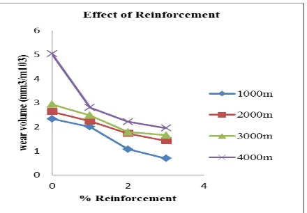
Effect of Reinforcement
Figure5.3 (b) shows the variation in volume loss versus different percentages of boron
carbide reinforcement at different sliding distance at a constant sliding speed of 0.84m/s and
for a 20N load for a fixed sliding distance of 4000 m. as the reinforcement content increase,
the wear resistance of the composite increases. A drastic decrease in wear volume was
observed for composites with 3 percent of boron carbide. As the amount of reinforcement
increases, the wear resistance increases for all sliding distances.
Figure 5.3(b): Variation of Wear Volume loss v/s different Reinforcement of B4C and constant Ti at variation sliding with sliding speed.
CONCLUSION
Stir casting process were used in the preparation of AL-Mg hybrid composites containing
varying % of Micro Ti and B4C particulates as reinforcement. And the test specimens were
prepared according to ASTM standards. The wear result of Al-Mg hybrid composites
increased with the increase in speeds hence wear is maximum for higher speed. The wear rate
for a particular speed was reduced as the percentage of the reinforcement was increased.
REFERENCES
1. Satyappa ISSN 1392–1320 MATERIALS SCIENCE (MEDŽIAGOTYRA). Vol. 11, No.
3. studies Dry Sliding Wear Behaviour of Hybrid Metal Matrix Composites, 2005.
2. Ibrahim, I. A., Mohamed, F. A., Lavernia, E. J. Metal Matrix Composites. A Review
Journal of Material Science, 1991;26: 1137 – 1157.
3. Sinclair, I., Gregson, P. J. Structural Performance of Discontinuous Metal Matrix
Composites Material Science and Technology, 1997;3: 709 – 725.
4. Ajitkuumar, Senapati, Saurabh, Srivastava, Atmanada Ghadai,Ranjith Kumar, Atul Kujur,
Effect of Reinforecement on Abrasive wear of Different Aluminium based Metal Matrix
Composite-A Review, IJETT, 2014; 8.
5. S. C. Mishra, Pratusa, Swayam, A. K. Mishra, S. C. Panigrachi, B. P. Samel, Studies on
Erosion wear behaviour of Aluminium-3Magnesium-10 silicon Carbide Composite,
ISSN:, 2231-3818.
6. K. Vijaya Bhaskar, B. Subba Rao, S. Sundarrajan, K. Ravindra, SSRG International
Journal of Mechanical Engineering – (ICEEMST’17) - Special Issue- March 2017, Wear
of Aluminium Metal Matrix Composites - A Review.
7. S. Basavarajappa, G. Chandramohan, K. Mukund, M. Ashwin, and M. Probes, Dry
sliding Wear behaviour of AA2219/Si Cp-Gr Hybrid metal Matrix Composites”, A
stattical Approach, JMEPEG, 2006; 15: 668-674.
8. S. Basavarajappa, G Chandramohan, K. “Dry sliding behaviour of Ametal Matrix Composites”, A stattical Approach, JMEPEG, 2006; 15: 656-660.
9. Siddesdh Kumar N G, Ravindranath V M,G S Shiva Shankar, Dry sliding wear behaviour
of hybrid metal matrix composites, International journal of Research in Engineering and
Technology eISSN, 2319-1163.
10.R. Balaji, Dr. S. V. Suresh Babu,, Dr. Channankaiah3, Wear Behaviour Of Sintered
Titanium-Diboride Reinforced Graphite Aluminium Composites, (IJERT), ISSN:
2278-0181 ,IJERTV3IS030395, 2014; 3(3).
11.Manoj singla1, et al., Study of wear properties of al-sic composites,Journal of minerals &
materials characterization & engineering, 2009.
12.Amardeep Singh, Ajay Singh Rana2 and Niraj Bala, Study on Wear Behaviour of
Aluminium based Composites fabricated by stircasting technique, Int. J. Mech. Eng. &
Rob. Res., 2015.
13.M. Manikandan and A. Karthikeyan, a Study on Wear Behaviour of Aluminium Matrix
14.Ramachandra, M.; Radhakrishna, K, Sliding wear, slurry erosive wear, and corrosive
wear of aluminium/SiC composite, Materials Science (0137-1339), 2006; 24(2): 333.
15.K. Siva Prasad, S. P. Kumaresh, babu, S. Natarajan, R. Narayanaswamy, Study on
abrasive and erosive wear behaviour of Al 6063/TiB2.
16.Chattopadhyay, R. Surface Wear - Analysis, Treatment, and Prevention. OH, USA:
ASM-International. ISBN 0-87170-702-0, 2001.
17.Jones, M., H., and D. Scott, Eds. Industrial Tribology: the practical aspects of friction,
lubrication, and wear. New York, Elsevier Scientific Publishing Company, 1983.
18.Williams, J. A. "Wear and wear particles - Some fundamentals." Tribology International,
2005; 38(10): 863-870.
19.A. Vencl, A. Rac, I. Bobic, Z. Iskovic, Tribological Properties of Al-Si Alloy A356
Reinforced With Al2O3 Particles; Tribology in industry, 2006; 28(1&2).
20.A. Baradeswaran, A. Elayaperumal; Effect of Graphite Content on Tribological behaviour
of Aluminium alloy - Graphite Composite ,European Journal of Scientific Research,
ISSN, 2011; 53(2): 1450-216.
21.K. Naplocha, K. Granat: Wear performance of aluminium / Al2O3/C hybrid composites.
22.Amro M. AI-Qutub Ibrahim M. Allam, M. A. Abdul Samad: Wear and friction of
Al-A1203 composites at various sliding speeds: Journal of Mater Science, 2008; 43:
5797-5803.
23.A. Vencl, A. Rac, I. Bobic, Z. Iskovic, Tribological Properties of Al-Si Alloy A356