Investigation of the propagation electromagnetic
wave with plasma layers and study of Switched
plasma half-space A and B Waves
Talebian Rizi Ahmadreza
1*, Hossini moradi Seyed Ali
2,
HassanzadehAtayi Ebrahim
31. Department of Physics, University of Khatamolanbiya, Tehran , Iran 2. Department of Physics, University of Khatamolanbiya, Tehran , Iran 3. Department photonic Graduate University of Advanced Technology iran
ABSTRACT: In this paper we used maxwell equation to solve the wave equations for plasma layer. transverse waves in cold, low-density and uniform non-magnetic plasma investigated. The plasma layer is steady state and non-steady state, cold. The resulting reflected and transmitted waves have an upshifted frequency and these will be labeled as B waves Step profiles that are mathematical approximations for fast profiles and provide insight into the physical processes as well as serve as reference solutions for a perturbation technique we will to consider next a problem that involves simultaneous consideration of the effects of a temporal discontinuity and a spatial discontinuity. also, with analysis of government equations, the results are obtained. finally, field amplitude of magnetic field for different states is studied and variations of them in term of different parameters are plotted also, results and optimum conditions are discussed and some suggestions are offered.
Keywords: maxwell equation, magnetic plasma , steady state
INTRODUCTION
Plasma is a mixture of charged particles and neutral particles. The mixture is quasi neutral. plasma is characterized by two independent parameters for each of the particle species. these are particle density (N( and temperature (T). Plasma physics deals with such mixtures. There exists a vast amount of literature on this topic. they deal with modeling magnetized plasma as an electromagnetic medium. the models are adequate in exploring some of the applications where the medium can be considered. There are some applications where the thermal effects are unimportant. Such plasma is called cold plasma lorentz plasma [1] is a further simplification of the medium. In this model, it is assumed that electrons interact with each other only through collective space charge forces and those heavy positive ions and neutral particles are at rest. Positive ions serve as a background that ensures overall charge neutrality of the mixture. In this paper, the lorentz plasma will be the dominant model used to explore the major effects of a no periodically time-varying electron density profile N(t). departure from the model will be made only when it is necessary to bring in other relevant effects.
1-waves in Magnetic cold plasma
If we apply an external magnetic field in a cold plasma, anisotropy in the plasma is created. the dispersion relation of the following equation (1) is obtained:
2 2
4
2
2
2
sin cos cos 1 cos 0
S
P
n RL
SP
n PRL 97 ( 2 ) 4 2 2 2 2 4 2 2 2 2 2 2 2
1 i
2 1
i
4 1
i
1
b b b p p pSin
Sin
Cos
that in the above equation,
is the angle between the external magnetic field and the plasmaenvironment. b eb
mc
is the magnetic frequency and2
p
ne mc
is plasma frequency. therelationship between permittivity and refractive index of plasma factor is calculated by the following equation.
coefficients are calculated using the following formula
the real and imaginary coefficients are calculated using the following formula
2- Steady-State Solution
Figure 1 shows the electron density N(t) of a typical transient plasma and its approximation by a step profile. Figure 2 shows the geometry of the problem. a plane wave of frequency (ω) is traveling in free space in the z-direction when, at t=0 a semi-infinite plasma of electron density N0 is created in the upper half of the plane z >0. The reflected wave will have two components denoted by subscripts A and B. There is no special significance to the choice of these letters for the subscripts. The A component is due to reflection at the spatial discontinuity at z= 0. Subscript S will be used to indicate scattering at a spatial boundary
Figure1-electron density N(t)versus time of a typical transient plasma.
corresponding reflection coefficient is where: 2 0 0 0 0 P A S P
n
n
R
R
n
n
(6)( 3 ) ( 4 ) ( 5 )
2 22 2 2 1
2
2 2 2 2 2 2
1 1
( 1 1 )
2 2
p b p b p
b b b
c
n
98
0
0 2
2 0
1
P
p
n
n
(7)2
p
ne mc
(8)here, n0 is the characteristic impedance of free space
n
p0is the characteristic impedance of the plasma medium, and the other symbols have the usual meanings [5]Figure2-geometry of the steady-state problem
The B component arises due to the wave reflected by the temporal discontinuity at t=0 and say z=z1. Jiang [3] showed that this wave is of a new frequency ω
and has a relative amplitude (relative to the incident wave amplitude)
the subscript t indicates scattering due to the temporal discontinuity. the wave will travel along the negative z-axis. When it reaches the spatial boundary at z=0, a part of it will be transmitted into free space. The corresponding transmission coefficient is
Where
the B component of the reflected waves in free space has a relative amplitude
(9)
2 2
0 p
(10) 0
2
t
R
(11) 0
0 0
2
/
S
T
(12) 0
2 2 1 p
p
(13) B t S
99
In considering the steady-state values (t→∞), the B component can be ignored since this component will be damped out in the traveling from z=z1= ∞ to z=0, even if the plasma is only slightly loss y. a quantitative idea of the damping of the B wave will now be given by calculating the damping constants for a low-loss plasma. let ν be the collision frequency, and let (ν/ωp)<<1. The attenuation constant α of the B wave of frequency ω is given by equation 14 .
after simplifying the algebra,
equation 15 shows that αis large for small values of ω0. when the incident wave frequency ω0 is low, the frequency ω of the B wave is only slightly larger than the plasma frequency ωp, and the B wave is heavily attenuated due to attenuation, RB is now modified as
a damping distance constant
z
p can now be defined:In traveling this distance
z
p the B wave attenuates to e−1 of its original value. The attenuation can be expressed in terms of time rather than distance by noting thatwhere tp is the damping time constant of the B wave and vg is the group velocity of propagation of the B wave given by
from equations 18 and 19 through 20
(14) 2
3 2 2 0
2
1
,
p
p
p
c
(15) 2
0
2
,
p
p c
(16) 1
z
B t S
R
RT e
(17) 1
p
z
(18) p
p g
z
t
(19) 2
0 2
0
1
pg
v
c
(20) 2
2
2
,
p p
p
100
the amplitude of the B wave reduces to e−1 of its original value in time tp. numerical results are discussed in terms of normalized values. let
In terms of these variables, from equations 20, 21, 22 , equations 23 through 24 are obtained: 2
2 1
12 21 2
n
n
R
R
n
n
(22)2
12 2
cos
Sin
R
cos
Sin
(23)2
12 12
2 2
12
1 2 1
1
[ s( )]
s d
d
R e R
R
R e (24)
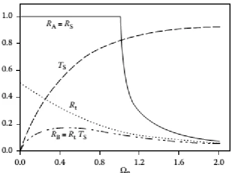
where λp is the free-space wavelength corresponding to the plasma frequency the amplitude of the reflected wave generated in the plasma by the temporal discontinuity decreases as the incident wave frequency ω0 increases (plasma frequency ωp being kept constant). This is to be expected since the plasma behaves like free space when ω0 ωp. on the other hand, the transmission coefficient TS at the spatial discontinuity increases with ω0. Thus, the reflection coefficient of the B wave increases, attains a maximum, and then decreases as ω0 is increased. The variation of the two reflection coefficients (RA and RB is shown in Figure 3 and is discussed next.
Figure 3 damping time constant tp versus Ω0.
For Ω0<1,|RA| is 1 and RB reaches a peak value of about 17% at about Ω0=0.5. For Ω0>1,RA falls quickly and RB falls slowly, both reaching about 5% at Ω0=2. for Ω0>2, RB/RA≈1.when the incident wave frequency is large compared to the plasma frequency, the total reflection coefficient is low, but each component contributes significantly to this low value. figure 3 shows the damping time constant tp for Ωc=0.
Log–log ale is used here. from this graph it is evident that for large ω0, the B component persists for a long time in low-loss plasma. for small ω0, this component is damped out rather quickly. figure 4 shows the damping distance constant zp.
(21)
,
,
pb
b c p
101
figure 4 transient Solution
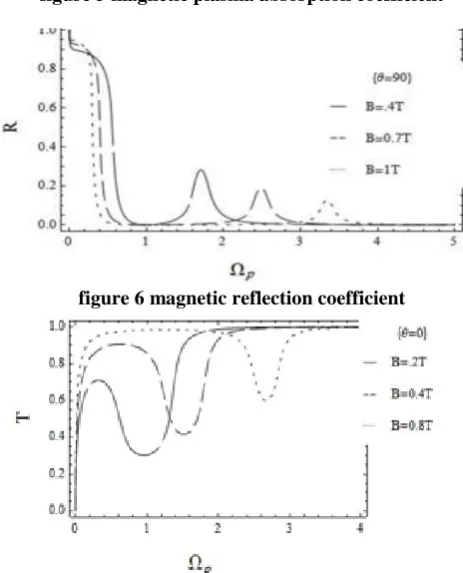
figure 5 magnetic plasma absorption coefficient
figure 6 magnetic reflection coefficient
102 3 -Transient response
A perpendicularly polarized plane wave is propagating in the z-direction when, at t=0, a semi-infinite plasma of particle density N0 is created in the upper half of the z plane. Let the electric field of the incident wave be aAnd k0=ω0/c. the equations satisfied by Ey are
Figure8:effect of switching an isotropic plasma slab. Reflected and transmitted waves are sketched in the time domain to show the frequency changes.
To solve the partial differential equations, due to the initial conditions can always use the laplace transform with ordinary derivatives conversion, then the solution of ordinary differential equation which is far easier to deal with. Therefore by applying Laplace transform if:
equation 29 is transformed into (here, =∂/∂t)
from the initial conditions,
If we assume that
and
(25)
2 2
1 1
2 2 2
( , ) 1 ( , )
0 0, 0
E z t E z t
z t
z c t
(26)
( , ) ( , )
i i
E z s L E z t
(27)
( , ) ( , )
i i
E z s L E z t
(28)
(0)L f s L f f
(29)
2
0 2
1
1 1 0 0
2 2
( , )
( , ) s j exp
d E z s
q E z s E jk z
dz c
(30)
2
0 2
2
2 2 0 0
2 2
( , )
( , ) s j exp
d E z s
q E z s E jk z
dz c
(31)
2
0 2
3
1 3 0 0
2 2
( , )
( , ) s j exp
d E z s
q E z s E jk z
dz c
(32) 1
s
q
103
field components in three regions:
the boundary conditions are
field components in three regions:
1 0 ( ) ( ) ( ) R A B A
s R s R s
E (40)
2 2 2 2 2 0exp(
) exp(
)
( )
pA
q d
q d
s
R
s
DR
s
(41)0 0 0
4
0 2 2
0 0
cos( ) sin( ) ( ) ( ) ( )
R
A B
s k d k d
A
s T s T s E
E s
(42)
In the above equations, it is assumed that at t=0 the newly created electrons and ions of the plasma are stationary so that the tangential components of the electric and magnetic fields are the same at t=0 as at t=0 [3]. from equations 40 through 41,
2 2
0 0
1 2
2 2 2 2 2 2
0 0
sin(
)
( )
p( )
( )
B B B
p p
s
k d
T
s
T
s
T
s
s
s
(44)The solution of this ordinary differential equation is given by
(33)
2 2
2 p
s
q
c
(34)
0
1 1 1 2 2 0
0
( , )
exp
s
j
exp
0
E z s
A
q z
E
jkz
z
s
(35)
0
2 2 1 3 2 2 2 2 0
0
( , ) exp exp exp 0
p
s j
E z s A q z A q z E jkz z d
s
(36)
0
3 4 1 2 2 0
0
( , )
exp
s
j
exp
E z s
A
q z
E
jkz
z
d
s
(37)1
(0, )
2(0, )
E
s
E
s
(38)
0 0 0
1 1 1 0 2 2
0
cos(
)
sin(
)
( , )
Rexp
s
k z
k z
0
E z s
A
q z
E
z
s
(39)
0 0 0
3 4 1 0 2 2
0
cos(
)
sin(
)
( , )
Rexp
s
k z
k z
E z s
A
q z
d
E
z
d
s
(43)
2 2 2
2 2
0
4
( )
pA
s
s
T
s
DR s
(45)
2 2
1
2
( )
p104
Which
DR
is calculated from the following equation
Figure9:electric field of reflected waves versust for the case of switching a lossless plasma half-space
.
Figure10:electric field of transmited waves versust for the case of switching a lossless plasma half-space
The numerical results are considered for p 1. p 1 (free-space wavelength corresponding to plasma frequency). the electric fields of the reflected and transmitted waves are normalized with respect to the strength of the electric field (E0) of the incident wave. Figure 5.2 presents reflection coefficients at z=0 versus for the semi-infinite problem. the results are obtained by performing numerical Laplace inversion of Equations 5.32 and 5.33 shows a frequency of shows a frequency of ω1 as it approaches infinity. the parameter ω0is chosen as 0.4 since it is known from previous work [2] that RB will have maximum amplitude at about this value ofω0. In this idealized model of lossless plasma, RB will persist forever and its amplitude has a nonzero steady-state value. this phenomena can be physically explained in the following way one of the B waves generated at t=0 and z=∞propagates in the negative z-direction and emerges into medium 1 at t=∞
REFERENCES
[1] Paul, M. Bellan, Fundamentals of plasma physics, Springer, New York, 2004 [2] Alexander Fridman, Plasma chemistry, Cambridge University Press, New York, 2008. [3] Kostaya Ostrikov, Plasma mnanoscience, Wily- vct, 2008
[4]Takashi Fujimato, Atsushi Iwamae, Plasma Polarization spectoroscopy, Springer, London, 2008.
(46)
2 2
2 2 2 2
2 2
2 0 0
exp( ) exp( )
( ) cos( ) p cos( ) p
B
s s q d s s q d
T s k d k d
DR DR
(47)
2
22 2 2 2
2 2
exp( ) exp( )
p p
105
[6] J. P. Royner, A. P. Whichello, Physical charactristics pf plsma antennas, IEEE Transaction Plasma science, 32, 269-281, 2004.
[7] Stutzman, L. Warran, Garry. A. Thiele, Antennas Theory and design, USA, J Wiley, 1998. [8] C.P. Narayan, Antennas and propagation, Techical publication, 159, 2007.
[9] Fujimoto, K., Mobile Antenna Systems Handbook, Artech House, June, 2008.
[10] Rayner, J. P., Wichello, A. P. and Cheetham, A. D.,“Physical Characteristics of Plasma Antennas,” IEEETransaction on Plasma Science, Vol. 32, No. 1, Februery,
2004, pp. 269-281.
[11] Kumar, R. and Bora, D., “A Reconfigurable PlasmaAntenna,” Journal of Applied Physics, Vol. 107, No.5,2010, pp. 053303-1–053303-9.
[12] Kumar, R. and Bora, D. “Wireless Communication Capability of a Reconfigurable Plasma Antenna,” Journalof Applied Physics, Vol. 109, No.6, 2011, pp. 063303-1 -
063303-9.
[13] Sadeghikia, F., Hodjat-Kashani, F., Rashed-Mohassel, J.,and Ghayoomeh Bozorgi, J., “Characterization of a Surface Wave Driven Plasma Monopole Antenna,” Journal of Electromagnetic Waves and Applications, Vol. 26, No. 2-3, 2012, pp. 239-250.
[14] Cerri, G., Leo, R. D., Primiani, V. M., and Russo, P., “Measurement of The Properties of a Plasma Column Used as a Radiating Element,” IEEE Transaction on Instrumentation and Measurement, Vol. 57, No. 2, 2008, pp. 242-247. [15] Cerri G., Leo R. D., Primiani V. M., and Russo P., “Measurement of The Properties of a Plasma Column Used as a
Radiating Element,” IEEE Transaction on Instrumentation and Measurement, Vol. 57, No. 2, 2008, pp. 242-247. [16] J.A . Bittencourt. ( Fundamental of Plasma Phys).
[17] M. Moisan, A. Shivariva and A. W. Rrivelpiece, Plasma Phys, Vol.24, No.11, P.1331, 1982 .
[18] Zhoaxian Zhou, ( Application of Plasma Columns to RF Antennas), Submitted to EECE 555 Gaseous Elextronics, Spr.2000.
[19] G. G. Borg, I. V. Kamenski., J. H. Harris, D. G. Miljak, and N. M. Martin, Defense Science and Technology Organisation P. O . Bax 1500, Salisbury, South Australia, 5108.
[20] W. Manheimer , Plasma reflector for electronic Beam steering in Radar system, IEEE Transmissions on plasma science, Vol. 19, No. 6, P. 1228, 1993.
[21] J Mathew, et al, Electronically steerable plasma mirror for radar applications, IEEE International Radar Conference, P. 742, 1995.
[22] US Patriot Scientific Corporation, U. S. Patent Application Number 5594456 J. D. [23] Timothy . Etc, IEEE. Trans. Antena, Vol. AP-32. No. 2, P. 141, 1984.
[24] L. Dlandau, E. M. Lifshiftz. Electrodynamics of Continuous Media. Oxford, 1976.
[25] A. W. Trivelplece, and R. W. Gould, Journal of Applied physic, Vol. 30, No. 11, P. 1784, Nov 1959. [26] ASI Technology Corporation web page "http//www.asiplasma.com.
[27] G. G. Borg, J. H. Harris, N. M. Martin, D. Thorncraft, R . Milliken, D. G. Miljak, B. Kwan, Phys of Plasma , Vol. 7, No. 5, P. 2198, May 2000.
[28] F. Chen, Plasma Phys and Controlled Fusion, Vol. 33. No. 4, P 339, 1991. [29] H. Blevin, and P. Christiansen. Australian Journal of Phys, Vol. 19, P. 501, 1966.
[30] V. V. Sinkov, V. A. Soshenkov, Plasma Antena, e-mail :vas @ nord.vostok. net. National Academy of Siences of Ukrain, 2003.
[31] J. R. Vail, Laser beam techniques, U. S. PATENT. 3-719-829, 1973..
[32] L. M. Vallese, A. Shostak, Laser beam antenna, Patent, No. 3, 404, 403, Oct, 1968.
[33] Anderson et al, Laser Driven Plasma Antenna Utilizing Laser Modifies Maxwellian Relaxation, US PATENT. No. US6-650-297-B2-, Nov 2003.
[34] S. Tzortzakis, S. D. Moustaizis, B. Lamouroux, A. Chiron, M. A. Franco, and A. Mysyrowicz, Subpicosecond UV Laser pulse Filamentation in Atmosphere, To Apear.
[35] S. Tzortzakis, M. A. Franco, B. Lamouroux, B. S. Prade, Physical Rev E. Vol. 60, No. 4, p. 3505. 1999.
[36] X. M. Zhao, J. C. Diel, C. Y. Wang, and J. M. Elizondo, IEEE Journal of Quantum Electronics, Vol. 31, No. 3, p.599, 1995.
[37] Dr. Kendall, L. Read, Included Local EMP and second THZ radiation in sensor window materials from intense femtosecond pulses at long range. Defense Air-force research project agency (DARPA), 77 phase 1 selection from the 0.2 solicitation 2004.
[38] N. A. Krall, A. W. Trivelpiece. MacGraw-Hill. NeW York, 1973.
[39] C. L. Jiang, Wave propagation and dipole radiation in a suddenly created plasma, IEEE Trans, Atennas Propag, 83, 23-51, 1975.
[40] D. K. Kalluri, On reflection from a suddenly created plasma half-space: transient solution, IEEE Trans, Plasma Sci., 16, 11, 1988.
[41] D. K. Kalluri, Effect of switching a magnetoplasma medium on a traveling wave: longitudinal propagation, IEEE Trans. Atenna propag, Ap-37, 1638, 1989.
[42] E.S . Weibel, On the confinement of a plasma by magnetostatic fields, Physics of Fluids 52–56, 1959.
[43] V.S. Markin., A.A. Chernenko, Y.A. Chizmadehev, Y.G V. Chirkov, Aspects of the theory of gas porous electrodes, in: V.S. Bagotskii, Y.B. Vasilev (Eds.), Fuel Cells: Their Electrochemical Kinetics, Consultants Bureau, New York, PP: 21–33, 1959.