www.ijaera.org 2016, IJA-ERA - All Rights Reserved 223
Influence of Gas Flow and Heat Input on Weld
Bead Width at Mag Welding
Gurkirat Singh, Avtar Singh & Parveen Kumar Saini*
Assistant Professor, Mechanical Engineering Department. CEC, Landran, Mohali
Abstract: At Metal active gas welding process, the selection of main welding parameters has great influence on welding joints properties but the selection itself depends of numbers of influences, like type and thickness of base metal, groove type, welding position etc., but the proper selection of welding parameters is also very important. Due to that, the analysis of weld bead geometry at MAG welding process with regard to weld current, voltage and weld speed (heat input) and the type and shielding gas flow is analyzed in this paper. The assumption that the proper selection of gas flow and heat input will reflect trough weld joint with satisfactory geometrical characteristics will be researched in this paper. Keywords:MAG Process, Welding Parameters, Weld Bead Width
I. INTRODUCTION
Metal active gas welding (MAG) is, due to its good characteristics (above all flexibility and low price), one of the frequently used welding processes; in welding and surfacing in production, but also at reparation welding of most metal materials. Besides its other advantages, like, wide range of weldable materials and filler metals, the possibility of welding in all welding positions, good quality and mechanical properties of weld joint, it is necessary to mention the possibility of automation and robotization. At MAG welding process, the selection of main welding parameters (welding current and voltage, filler wire diameter, welding speed, shielding gas composition and flow rate, wire stick out etc.) has great influence on weld joint properties, but the selection itself depends of type and material thickness, joint geometry and welding position. Also, the correct choice of filler material, shielding gas and welding parameters will result with stabile welding process without appearance of welded joint failures and quality deviations.
www.ijaera.org 2016, IJA-ERA - All Rights Reserved 224 voltage, Tip distance and decrease with Arc Travel Speed and remains constant with welding current [10].
The goal of this investigation was to confirm the assumption that the proper selection of gas flow and welding speed (heat input) will reflect trough weld joint with satisfactory geometrical characteristics, therefore, the hypothesis of this paper is: there is the influence (connection) between heat input (weld speed) and gas flow on the weld bead width at MAG welding process.
Experimental research of MAG welding process with two types of filler material and two types of gas shielding composition are provided in this paper.
II.EXPERIMENTALPROCEDURE
Since the dimensions of the bead on plate at MAG welding process is influenced by number of factors, in this investigation the two of them are selected: gas flow (l/min) and heat input (kJ/mm). The type, filer metal marks and diameter of welding wire used in experiment are shown in table 1. With cited filler materials, the experimental welding was performed: using shielding gas – carbon dioxide (C1 according to EN 439) as well as mixture of 18 % carbon dioxide and 82 % argon, called Krysal 18 (M21 according to EN 439).
Table 1. Filler Materials Used In Experimental Welding
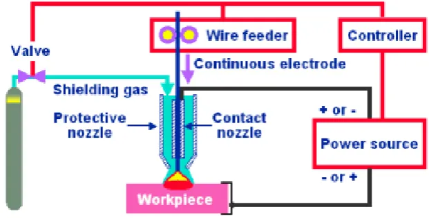
Measurement of welding parameters and monitoring of electric arc stability was performed by acquisition of welding current and voltage with on-line monitoring system. Figure 1 shows block diagram of experimental setup. Surfacing was performed by automatic MAG welding process with TPS 4000 power source (Fronius International GmbH, A). Tracking Vehicle FTV 4 connected to Control Unit FCU – 4 – RC remote control (both made by Fronius International GmbH, A) was used for the welding speed setup.
Figure 1. Block Diagram of the experiments
Filler metal type
Filler metal mark according to standard
Wire diameter, ø
mm Producer mark Producer
Solid wire G Mo Si (EN 12070) 1,2 DMO-IG Böhler, D
Rutile flux cored wire
T MoL P M 1 H5 (DIN
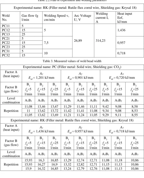
www.ijaera.org 2016, IJA-ERA - All Rights Reserved 225 Welding was performed on horizontal position on 16 Mo 3 steel plates (according to DIN standards, EN 10028 -2 according to EN). In this paper the influence of the selected welding parameters on the weld bead width was analysed on two examples: welding wit solid wire with shielding gas CO2 and with rutile flux cored wire with shielding gas Krysal 18 (table 2). The selected factors are varied on three levels so for every combination of the filler metal and shielding gas there are 9 experiment levels. The scheme of experimental investigation plan and the values of welding parameters for individual experiment levels are shown in table 2.1 and 2.2. Since full factorial designs in three levels 32 with 3 replication were used to obtain the required information, there was totally 2×27 specimens with different heat input and gas flow welded and the bead width was measured for all cases.
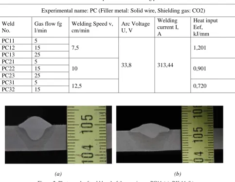
After finishing the welding processes, the specimens were cut in order to measure the bead width b, mm. The macro-structure photos were taken from the etched surfaces, and the bead width measurements were done by using a UTHSCSA Image Tool (IT); Department of Dental Diagnostic Science at The University of Texas Health Science Center, Texas USA [6]; program. A schematic illustration of bead penetration measurement is shown on figure 2. The results of measurements and welding parameters are shown in table 3. The factors (A – heat input and B – gas flow) and their levels are defined. The values of the welding current and voltage are specified as the mean values of the measurement obtained by on-line monitoring system (sampling frequency was 10 kHz.
Table 2.1 Plan of experiment 6and welding parameters
Experimental name: PC (Filler metal: Solid wire, Shielding gas: CO2)
Weld No.
Gas flow fg l/min
Welding Speed v, cm/min
Arc Voltage U, V
Welding current I, A
Heat input Eef, kJ/mm PC11 5
7,5
33,8 313,44
1,201 PC12 15
PC13 25 PC21 5
10 0,901
PC22 15 PC23 25 PC31 5
12,5 0,720
PC32 15
(a) (b)
www.ijaera.org 2016, IJA-ERA - All Rights Reserved 226
Table 2.2 Plan of experiment and welding parameters
Experimental name: RK (Filler metal: Rutile flux cored wire, Shielding gas: Krysal 18)
Weld No.
Gas flow fg l/min
Welding Speed v, cm/min Arc Voltage U, V Welding current I, A Heat input Eef, kJ/mm PC11 5
5
26,89 314,23
1,436 PC12 15
PC13 25 PC21 5
7,5 0,957
PC22 15 PC23 25 PC31 5
10 0,718
PC32 15
Table 3. Measured values of weld bead width
Experimental name: PC (Filler metal: Solid wire, Shielding gas: CO2) Factor A
(heat input) E A1
ef = 1,201 kJ/mm
A2
Eef = 0,901 kJ/mm
A3
Eef = 0,720 kJ/mm
Factor B (gas flow)
B1 fg=5 l/min
B2 fg=15 l/min
B3 fg=25 l/min
B1 fg=5 l/min
B2 fg=15 l/min
B3 fg=25 l/min
B1 fg=5 l/min
B2 fg=15 l/min
B3 fg=25 l/min Level
combination A1B1 A1B2 A1B3 A2B1 A2B2 A2B3 A3B1 A3B2 A3B3
Repetition
11,08 13,46 13,67 11,29 11,46 11,11 9,42 9,08 8,58 11 13,62 13,72 11,42 11,41 11,08 9,34 9,08 8,53 11,05 13,62 13,69 11,21 11,24 11,05 9,29 9,11 8,55 Experimental name: RK (Filler metal: Rutile flux cored wire, Shielding gas: Krysal 18) Factor A
(heat input) E A1
ef = 1,436 kJ/mm
A2
Eef = 0,957 kJ/mm
A3
Eef = 0,718 kJ/mm
Factor B (gas flow)
B1 fg=5 l/min
B2 fg=15 l/min
B3 fg=25 l/min
B1 fg=5 l/min
B2 fg=15 l/min
B3 fg=25 l/min
B1 fg=5 l/min
B2 fg=15 l/min
B3 fg=25 l/min Level
combination A1B1 A1B2 A1B3 A2B1 A2B2 A2B3 A3B1 A3B2 A3B3
Repetition
www.ijaera.org 2016, IJA-ERA - All Rights Reserved 227
III. ANALYSIS OF EXPERIMENTAL RESULTS
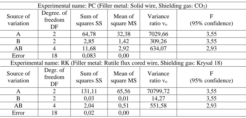
Analysis of the values of the weld bead width at this experiment is conducted by Analysis of Variance [9, 10] (since the information on significance of effects can be gained by this analysis) and the results are shown in table 4.
Table 4. Analysis of variance
Experimental name: PC (Filler metal: Solid wire, Shielding gas: CO2)
Source of variation
Degree. of freedom
DF
Sum of squares SS
Mean of square MS
Variance ratio vo
F
(95% confidence)
A 2 64,78 32,38 7029,66 3,55
B 2 2,85 1,42 309,26 3,55
AB 4 11,68 2,92 634,07 2,93
Error 18 0,083 0,00
Experimental name: RK (Filler metal: Rutile flux cored wire, Shielding gas: Krysal 18)
Source of variation
Degr. of freedom
DF
Sum of squares SS
Mean of square MS
Variance ratio vo
F
(95% confidence)
A 2 131,11 65,56 70799,72 3,55
B 2 0,03 0,01 14,27 3,55
AB 4 2,04 0,51 551,58 2,93
Error 18 0,02 0,00
From the comparison of the calculated variance ratio vo with the value F for 95% confidence it is visible
that factors A (heat input) and B (gas flow) are meeting criteria v0 >F. The interaction of these two factors also meets this criterion for 95% confidence.
IV.CONCLUSIONS
After conducted experimental welding and preparation of the specimens for macrograph analysis the bead on plate dimensions are measured (table 3, figure 2). The influence of the two effects: heat input (welding speed) and gas flow on the values of the bead on the plate width are investigated by analysis of variance for two cases: (a) welding with solid wire with gas shielding CO2 and (b) welding with flux cored wire with gas shielding Krysal 18.
The results of mentioned analysis have shown that in both cases (welding with solid wire with gas shielding CO2 and welding with flux cored wire with gas shielding Krysal 18) there is a significant influence of heat input and of mutual effect of heat input and gas flow. So in the following analysis, which would include the regression analysis, both of the researched effects should be taken in consideration.
Also, in a case of further investigation of the mutual effect of heat input and gas flow on the weld geometry at MAG welding process, the plan of experiment should be redefined and more researches conducted. Also, the attention should be given to porosity and other types of defects that appear on the weldments due to deficient or oversize quantity of the gas flow.
Conflict of Interest: The authors declare that they have no conflict of interest.
www.ijaera.org 2016, IJA-ERA - All Rights Reserved 228
REFERENCES
[1] Suban, M.; Tušek, J.: Dependence of melting rate in MIG/MAG welding on the type of shielding gas used, Journal of Materials Processing Technology, 119, 2003, 185-192.
[2] Kralj, S.; Andrić, Š.: Osnove zavarivačkih postupaka, Zagreb, Sveučilište u Zagrebu, Fakultet strojarstva i brodogradnje, 1992.
[3] Lyttle, K.; Garth Stapon W.F.: Choosing the right consumables to reduce welding costs, Danbury, SAD,
Praxair, Inc., 1997.
[4] Grbin, M.; Kovačević, B.; Živčić, M.: Elektrolučno zavarivanje u zaštiti plinova, Zagreb, UNIMEX, 1996. [5] Department of Dental Diagnostic Science at the University of Texas Health Science Center, San Antonio, Texas. (The program developed by C. Donald Wilcox, S. Brent Dove, W. Doss Mcdavid and David B. Greer), http://ddsdx.uthscsa.edu/dig/itdesc.html, 20.11.2007.
[6] Lukačević, Z.: Zavarivanje, Slavonski Brod, Sveučilište J.J Strossmayera u Osijeku, Strojarski fakultet u Slavonskom Brodu, 1998.
[7] Grbin, M.; Kovačević, B.; Živčić, M.: Elektrolučno zavarivanje u zaštiti plinova, Zagreb, UNIMEX, 1996. [8] N. Šakić: Planiranje i analiza pokusa u istraživačkom radu, FSB, Zagreb 2002.
[9] Pantelić, I.: Uvod u teoriju inženjerskog eksperimenta, Novi Sad, Radnički univerzitet "Radivoj Ćirapanov", 1976.