RESEARCH ARTICLE
A Delay and Spectrum Aware Fuzzy Logic Based
Routing Protocol for CRN
Poonam
Department of Computer Engineering, YMCA University of Science and Technology, Faridabad, India.
[email protected]
Chander Kumar Nagpal
Department of Computer Engineering, YMCA University of Science and Technology, Faridabad, India.
[email protected]
Shailender Gupta
Department of Electronics and Communication, YMCA University of Science and Technology, Faridabad, India.
[email protected]
Abstract – Cognitive Radio (CR) is an intelligent technology used to sense the spectrum in order to make efficient use of limited spectrum available. The use of such radios in ad hoc network not only increases the probability of reach ability but also provides a reliable path between a pair of nodes. Networks that employ CR technology are termed as Cognitive Radio Ad Hoc Networks (CRAHN). Quality of route depends upon several parameters but it is highly influenced by end to end delay encountered by a packet to reach from source to destination. More is the end to end delay; lesser will be the efficiency of the network. End to end delay is directly concerned with the reliability of data transfer. Therefore this paper proposes a routing scheme that obtains a most reliable route with minimum end to end delay using fuzzy logic theory. The proposed strategy is implemented in MATLAB-7.0 and the simulation results show that our proposed routing scheme outperforms the traditional Shortest Spectrum Aware routing scheme available in literature.
Index Terms – Delay, Cognitive Radio Networks, Channel Assignment, Fuzzy Expert System.
1. INTRODUCTION
In recent years, the use of Cognitive Radios in Ad Hoc Networks (CRAHN) [1-4] has gained popularity due to its capability to sense channel intelligently [5]. CRAHN basically employs two types of nodes: Primary Users (PUs) and Secondary Users (SUs). PU nodes are allocated a licensed band and can use at its own will while SUs are the ones that depends upon PUs for their communication. In order to provide an efficient and reliable communication between a pair of distant nodes a routing protocol has to deal with following limitations [6]:
Limited Bandwidth Transmission Range Limited Battery power Mobility of Nodes
PU Activities
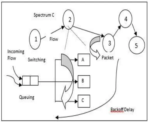
In such scenario a routing protocol should also ensure faster packet delivery. Otherwise it is assumed as packet drop and affects the overall performance of the network. Hence end to end delay is an important routing metric which is important for routing decisions. End to end delay is a path delay from source to destination. Path delay is a summation of intermediate CR node delay. Delay components of a CR node are shown in the Figure 1.
Figure 1 Delay components of a CR node
Main components of End to End delay are as under:-
RESEARCH ARTICLE
as store-and-forward delay. In other words, this is the delay caused by the data rate of the link. This delay is proportional to the packet’s length in bits.
d =N/R (1)
Where N is the number of bits and R is the rate of transmission
d =S/N (2)
Where S is the size of data packet and N is the number of bits
Queuing Delay: It is the time for which a packet waits in a queue to get a particular frequency band. When the processing time of a packet is slower than the traffic arrival, the amount of delay a packet has to wait going through the queue increases. The average delay can be given by:-
Q =1/ (µ-ג) (3)
Where µ is the number of packets per second and ג is the
average rate of arrival of packets to be serviced.
(Queuing Delay At time t)Path i = Max (k= S to D) in path i [(Time
instant when node k will be available) k – Current time t] (4)
Switching Delay:This delay occurs when a node switches its frequency band either from higher to lower or lower to higher. Switching delay is significantly smaller delay and measured in micro second or nano seconds. High-speed packet-switched network technologies are used to minimize this delay.
Propagation Delay:It is the time required for a bit to traverse to the required path of the transmission medium. It is the longest delay because it takes much time for the data packets to reach to destination.
(Propagation Delay)Path i= (Total Distance) Path i/Speed of Light (5)
Back-Off delay:This delay occurs when there is a collision and station waits for a random time before retransmission. If all the stations wait for same interval before retransmission, then collision may occur again. This is avoided by multiplying the interval with a random number and station will wait for this calculated time period before testing the carrier. This time period is known as the back-off delay.
There are few routing protocols that are available in the literature which talks about delay awareness. Few of the routing schemes uses one or more above discussed delays as routing metrics.
These routing schemes are discussed as follows:
1.1.A Spectrum aware on-demand Routing Protocol (SORP)
It was the first routing protocol [7] in which Switching Delay (SD) and the Back-off Delay (BD) within channels was considered to select routes.
TTD = TSD + TBD (6)
The value of Total Delay (TTD) is considered as a performance metric for route selection. The protocol has a disadvantage that due to multiple channels and absence of scheduling mechanism, channels are not efficiently utilized.
1.2.Delay motivated on-demand Routing Protocol (DORP)
This protocol is delay based on-demand routing protocol [8], where routing and spectrum assignment was considered together. In this routing polling-based scheduling channel allocation is used. DORP reduces interference between data streams and spectrum switching delay because each node has spectrum transceiver and traditional wireless communication interface.
Queuing Delay (QD) plays an important role in end-to-end delay in CRN. Total cumulative delay can be further expressed as:
T Cumulative Delay = T SD + T BD + T QD (7)
Selection of optimal frequency band provides most efficient route using the joint approach of switch decisions.
1.3.Multi-hop Single-transceiver CRN Routing Protocol (MSCRP)
MSCRP is based only on switching delay where switching delay has two components hardware switching delay and software switching delay [9]. Due to the presence of Single-transceiver LEAVE/JOIN messages have to be sent as a switching node switches the channel. Switching between channels would bring switching delay.
Settling of desired frequency raises delay in channel switching called as Hardware Switch Delay (D Hard-Switch). The hardware switching delay depends on the relative positions of the two channels on the radio spectrum.
D Switching = D Hard-Switch + D Soft-Switch (8)
This switching delay is used as routing metric in MSCRN but here channel scheduling is not taken into consideration as well as the protocol is ignorant towards queuing delay and back-off delay.
1.4.Local coordination based routing and spectrum assignment in multi-hop CRN
Delay based routing mechanism which selects optimal route on the basis of generalized cost function [10]. The generalized cost function is defined as:
C Generalized= D Route,i +D Queuing (9)
Here D Route,i is cumulative delay [9] which includes node delay, path delay. D Route,i is calculated as:
RESEARCH ARTICLE
DPi takes into account the switching delay and backoff delay caused by the path. DPi is defined as:
DPi = DSwitching, i + Dbackoff, i (11)
Advantageous feature of this protocol is its consideration for back-off delay. Local coordination of the nodes helps to decide back-off delay.
1.5.Opportunistic Service Differentiation Routing Protocol (OSDRP) for CRN
Minimum delay-maximum stability is the key feature of OSDRP [11]. It discovers the route in CRNs dynamically by considering the availability of spectrum in addition to switching delay and queuing delay across primary user networks.
RREP packet reflects the sum of the delays caused by switching and queuing for each node along the route and is defined as:
Delay (n0, nh) = ∑ (d switch + d queue)h (12) Where h is the number of hops between nodes n0 and nh. OSDRP provides clear differentiation between different traffic flow and no consideration of back-off delay in case of link failure.
1.6.Delay and Energy based Spectrum Aware Routing protocol (DESAR) for CRN
Key features of DESAR [12] is handling of spectrum heterogeneity and route jointly.
Cumulative Metric = Delay Metric (DM) + Path Energy (Eij)
(13)
Efficient path is selected by considering delay and energy together. Route delay comprises of path delay and node delay whereas path delay contains switching delay and backoff delay.
Delay Metric (DM) =D Route, i +D Queue (14)
Here queuing delay is considered in 2 different scenarios- if the sender node queuing the data and another scenario is if it a relaying node.
1.7.Low Latency and Energy based Routing (L2ER) protocol for CRN
L2ER [13], a reactive on-demand routing protocol considers both delay and residual energy as a routing metric for routing decisions. Packets travelling from source to destination experience different types of delays such as switching, medium access and queuing. Path delay (𝐷path, 𝑖) is defined as:
𝐷Path, 𝑖= 𝑆Delay, 𝑖+ 𝐵Delay,+ 𝑄Delay,𝑖 (15)
Where, 𝑆delay, 𝑖 is hardware switching delay and 𝐵delay, 𝑖 represents backoff delay and Q delay,i represents queuing delay.
Key feature of L2ER is it selects channel and route jointly without using Common Control Channel (CCC).
1.8.Robustness Aware Cognitive Ad-hoc Routing protocol (RACARP)
Trademark of RACARP [14] is its fast route recovery and robust path in the presence of PU activities. Expected Path Delay (EPD) is used as routing metric in joint path and spectrum diversity. Path that has no PU activity is selected.The EPD (p) represents the expected time it takes a probe packet to travel along a path p from a node to another node which can be defined as:
EPD (p) =∑𝐿𝑖𝑛𝑘 𝑙∈𝑝𝐸𝐿𝐷(𝑙) (16)
Where pis a path which are composed of the set of links. The ELD (l) that denotes the Expected Link Delay of the link l can be calculated as:
ELD (L) =ETX (l)*{RTT (l) /2} (17)
Where ETX (l) is the Expected Transmission Count of the link l, representing the expected number retransmissions required to successfully transmitting an ETX probe packet over the link l and RTT represents the round trip time of RTT probe packet. Here EPD routing metric considers link delay and effect of packet loss on wireless links.
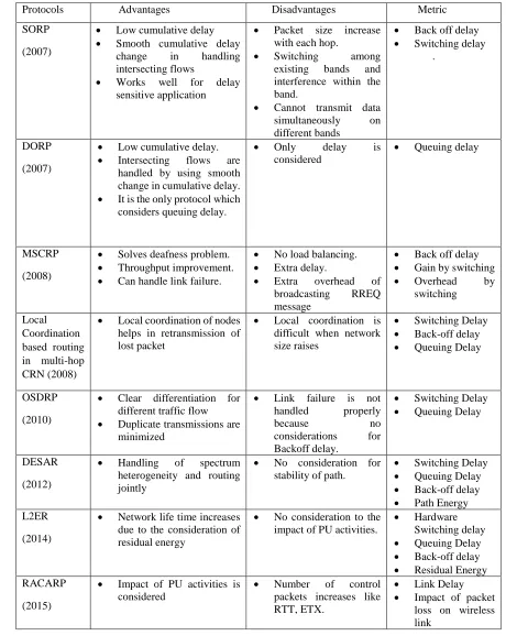
A comparative discussion of all the above presented routing techniques [7-14] is presented in the table 1.
All the presented routing techniques mainly focus on switching, back-off and queuing delay but none of them considered propagation and transmission delay. Impact of different delays is different and few may be ignorant in comparison of other. But the existing delay-aware routing techniques have same consideration to all delays. Therefore, this paper proposes a routing scheme that considers all these delay parameters to select optimal path. Role of these delay parameters is defined in the rule base using Fuzzy Logic [15-16] theory.
RESEARCH ARTICLE
Protocols Advantages Disadvantages Metric
SORP
(2007)
Low cumulative delay Smooth cumulative delay
change in handling intersecting flows
Works well for delay sensitive application
Packet size increase with each hop.
Switching among existing bands and interference within the band.
Cannot transmit data simultaneously on different bands
Back off delay Switching delay
.
DORP
(2007)
Low cumulative delay. Intersecting flows are
handled by using smooth change in cumulative delay. It is the only protocol which
considers queuing delay.
Only delay is considered
Queuing delay
MSCRP
(2008)
Solves deafness problem. Throughput improvement. Can handle link failure.
No load balancing. Extra delay.
Extra overhead of broadcasting RREQ message
Back off delay Gain by switching Overhead by
switching
Local Coordination based routing in multi-hop CRN (2008)
Local coordination of nodes helps in retransmission of lost packet
Local coordination is difficult when network size raises
Switching Delay Back-off delay Queuing Delay
OSDRP
(2010)
Clear differentiation for different traffic flow Duplicate transmissions are
minimized
Link failure is not handled properly because no considerations for Backoff delay.
Switching Delay Queuing Delay
DESAR
(2012)
Handling of spectrum heterogeneity and routing jointly
No consideration for stability of path.
Switching Delay Queuing Delay Back-off delay Path Energy L2ER
(2014)
Network life time increases due to the consideration of residual energy
No consideration to the impact of PU activities.
Hardware Switching delay Queuing Delay Back-off delay Residual Energy RACARP
(2015)
Impact of PU activities is considered
Number of control packets increases like RTT, ETX.
Link Delay Impact of packet
loss on wireless link
RESEARCH ARTICLE
2. PROPOSED DELAY AWARE ROUTING SCHEME
Before discussing, our proposed routing scheme, we would like to brief you about the fuzzy logic that we have used in our proposed so as to provide you with a better understanding of our proposed protocol.
2.1.Fuzzy Logic Controller
Fuzzy logic is a technology that deals with fuzzy data and helps in the development of intelligent control and information systems. It can model non-linear data and also helps in view and analyse the results of a complex system and provides the ease of describing human knowledge.
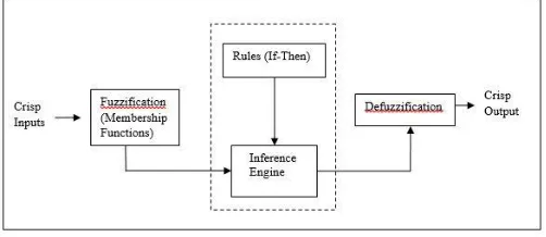
The basic blocks of Fuzzy logic controller (Figure 1) are described as below:-
Fuzzification Module:
This module takes each of the input value which is crisp (sharp) into a fuzzy set where fuzzy set is a set with smooth boundaries. The various types of membership functions defined in this are triangular, Gaussian etc.
Rule Base:
This can be defined as the set of rules based on conditions according to which certain actions are taken to perform a particular task. This module contains the conditional rules in the form of If-Then. This rule base is attached to the inference engine. The inference engine works on rule-base.
Inference Engine:
It can be defined as a computer program that tries to derive the answer from the rule base. It is attached to the rule base. It performs the functions based on the rule present in the rule base. It evaluates which control rules are relevant at execution time for current input and decides what to display as output.
Figure 2 Block diagram of Fuzzy Logic Controller
Defuzzification Module:
It is a module which converts the fuzzy outputs back into crisp (quantifiable) results. There are various defuzzification methods available like bisector, centre of area, centroid and
centre of gravity etc. But in our proposed method we used Centre of gravity (CoG) method of defuzzification.
2.2.FLC structure for Shortest Delay Aware Routing Protocol
Figure 3 indicates the block diagram of proposed routing scheme based on delay as input and optimal path is selected on the basis of output weights. The path with maximum output weight is given the highest priority.
Figure 3 FLC Structure for Proposed Routing Protocol
Steps involved in the working of FLC are as
follows:-1. The first step is that protocol computes the possible available routes and the value of delay for all these paths.
2. Next step is to apply the effect of delay to compute the best possible result using Mamdani FLC
3. Output of FLC is used to compute the crisp value of Optimality for the route. The route with greater output weight is considered as the best route.
The basic blocks of FLC are explained as below:-
Input to FLC-Delay: To compute the optimal route, the FLC uses Delay as input parameter. It can be defined as the time required for the data to reach from source to destination. The Total End to End Delay (TEED) is the sum of Transmission Delay (TD), Queuing Delay (QD), Switching Delay (SD) and the Propagation Delay (PD).The total end to end delay for any arbitrary path p can be calculated as:
(TEED) p= (TD+QD+SD+PD) p (18)
Fuzzification: Crisp value of delay is provided as input to the FLC. Then the Fuzzification process converts the crisp data into fuzzy set by using the membership functions as shown in the Figure 3.
Membership Function: A fuzzy set is defined by a function that maps objects in a domain of concern to their membership value in the set. Such a function is called membership function and is denoted by ‘µ’. Crisp values of input parameters are same but membership functions are different. The semantic variable for all input parameters is characterized as: {T (Input)} = {[Low, Medium, high]}
Input : Delay
Fuzzification Rule Base Defuzzification Output
RESEARCH ARTICLE
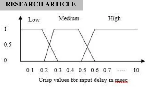
Figure 4 Membership Function for Delay
Equations for fuzzification:The equations which are used for fuzzification that defines the membership functions are as
follows:-FLC Input: Delay (D)
Low=1 if 0 ≤ D ≤ 0.2
= 3-10*D if 0.2 ≤ D ≤ 0.3
Medium= 10*D-2 if 0.2 ≤ D ≤ 0.3
=1 if 0.3 ≤ D ≤ 0.5
= 6-10*D if 0.5 ≤ D ≤ 0.6
High= 10*D-5 if 0.5 ≤ D ≤ 0.6
= 1 if 0.6 ≤ D ≤ 10
(19)
Rule Base:Rule base Table is used here by mamdani inference engine to infer the optimality of routes generated from multiple iterations performed by simulator.
1. If (Delay is low) then (Output is best)
2. If (Delay is medium) then (Output is moderate)
3. If (Delay is high) then (Output is poor)
Defuzzification: This module converts the data present in fuzzy set back to its crisp or sharp form. There are several methods for defuzzification like Centre of Gravity (CoG), bisector and mean of maxima etc. The output of FLC is the crisp value evaluated through membership function as shown in the figure 4. Method used for determining the defuzzified value is CoG method as shown in the
equation:-Output= (m1*A1+m2*A2) / (A1+A2) (20)
Where m1 and m2 are the membership functions determined through the Fuzzification process as {[Poor, Moderate, Best]} are selected on the basis of rules defined in rule base and A1, A2 are the areas in
the selected region. Output is the crisp value obtained by applying centre of gravity method on the obtained area A1 and A2.
Membership function for FLC output
The output variable of FLC is defined as optimality of the route. The semantic variable for output is characterized as {T (output)} = {[Poor, Moderate, Best]}. Figure 4 shows that optimality of a path lies between 0 to 1.
Figure 5 Membership Function for Output of FLC
Equations for defuzzification in FLC
The equations which are used for defuzzification that characterize the membership functions are as follows:-
FLC output: Optimality of Path (OP)
Poor= 1 if 0 ≤ OP ≤ 0.2
=2-5*OP if 0.2 ≤ OP ≤ 0.4
Moderate= 5*OP-0.5 if 0.1 ≤ OP ≤ 0.3
=1 if 0.3 ≤ OP ≤ 0.5
= 3.5-5*OP if 0.5 ≤ OP ≤ 0.7
Best= 10*OP-5 if 0.5 ≤ OP ≤ 0.6
= 1 if 0.6 ≤ OP ≤ 1
(21)
Obtained outputs are assigned some weights and the priority is given to route with maximum weight. The highest weight path is taken as the best path.
3. SIMULATION SET UP PARAMETER
RESEARCH ARTICLE
3.1. Performance Metrics used
Packet delivery ratio (PDR): It is the ratio of number of data packets delivered to a particular destination to the packets sent from source. Greater value of PDR indicates better performance of a protocol.
Transmission power: It is the total power consumed to forward data from source to destination. The path having minimum required transmission power indicates that nodes are less distant comparatively.
Delay: It is defined as the time needed to reach a data unit from source to destination. It has 4 constituents which are propagation delay, queuing delay, switching delay and transmission delay.
Hop Count: It is defined as the number of intermediate hops from source to destination in the selected path.
Throughput: It indicates the data rate or speed of the received data in bits per seconds or data packets per second. Data rate may differ in different nodes in a particular path.
Set-up Parameters Values
Area 1500*1500
Transmission Range 400
Nodes(SU) 24-36 (Step size 6)
Nodes (PU) 16
Position of SUs Random
Position of Pus Fixed
Max velocity 416 m/sec
Pause time 0 sec
Data rate (our-actual) 2 Mbps (PU), (0.5 – 1.5 Mbps)
No of iteration 25
Source Chosen randomly from SU
Destination Chosen randomly from SU
No of channels per
user/node 4
Simulation Time for 1
iteration 20 sec
Mobility Model Random walk
Table 2 Shows Set-Up Parameters Used in Our Experiment.
3.2.Snapshot
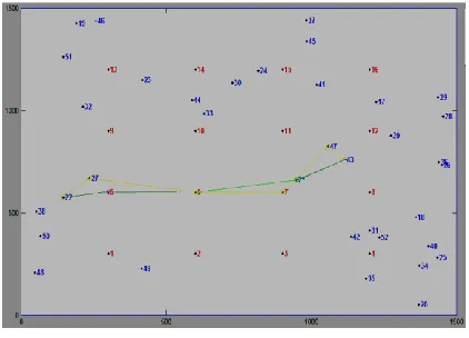
Snapshot of the simulation region is shown in the figure 6. Nodes in blue colour are SU nodes which are randomly placed and also move randomly in the region. Nodes in red colour are PU nodes which are fixed. Yellow line in the snapshot indicates shortest spectrum aware path from source to destination and green line indicate the path obtained from proposed QoS based protocol i.e. shortest delay and spectrum aware protocol. In the given snapshot, node 22 is the source and node 43 is the destination.
Figure 6 Snapshot of Simulation Process
3.3. Algorithm
The algorithm to evaluate the performance of the network in terms of performance metric is described as under. There are 16 nodes placed at fixed locations in the simulation region; each PU node has 4 channels. 25 iterations are performed by increasing the concentrations of SUs from 24 to 36 with a step size of 6. Multiple iterations execute on different source to destination pair to find the possible paths and all the QoS parameters are computed for every path and after many iterations average of all the iterations is computed for all QoS parameter. These crisp values of QoS parameters [12-18] are provided as input to FLC to find the optimal path.
Algorithm1. Pseudo-code description of QoS parameter calculation
P=16 //Deploy Primary Nodes P evenly where P is fix
Loop (Q=24 to 36) with a step size of 6 //Randomly deploy
secondary nodes Q varies from 24 to 36
Hop _count=0; //QoS -Hop count, Packet
Delivery Ratio (PDR), End to End Delay (EED) as 0
PDR=0;
EED=0;
Reach_ability=0; //Reach_ability indicates whether path exists between S and D
RESEARCH ARTICLE
Repeat while (Itr < 25) //Every scenario is iterated 25 times for random S and D
{
Randomly choose value of S and D from N=P+Q such that (S! = D)
If (path exists (S-D))
{
PDR= PDR + Send_ data ();
Hop _count = Hop _count + size (path);
EED = EED+ p_ delay () + s_ delay () + b_ delay ();
}
Reach_ability++;
Itr++;
}
PDR= (PDR)/Reach_ability; //PDR will be average of total PDR divide by total number of routes
Hop _Count =Hop_ count/ Reach_ability; // Average of hop count is the total hop count divide by reach ability
EED = EED/ Reach_ability; //Average of end to end delay is calculated
End loop;
4. RESULTS
4.1. Impact on PDR
Figure 7 Impact on PDR
Figure 7 shows the Average Packet Delivery Ratio (PDR) comparison of Shortest Spectrum Aware and Shortest Delay Aware Routing Protocol with varying number of secondary users. The result shows that PDR value is higher for our proposed routing scheme in comparison to the shortest spectrum aware routing protocol.
4.2. Impact on Throughput
Throughput indicates the rate at which data flows. Shortest Spectrum Aware considers only the path which is shortest and
Shortest Delay Aware selects a path which is shortest and has less delay. Figure 8 shows the comparison of Shortest Spectrum Aware and Shortest Delay Aware routing metric with varying number of Secondary nodes increasing from 24 to 36 at a step size of 6. Clearly, same throughput is obtained in both the cases.
Figure 8 Impact on Throughput 4.3. Impact on Hop Count
Figure 9 shows the comparison of Shortest Spectrum Aware and Shortest Delay Aware Routing protocol in terms of Hop Count with increasing Number of secondary users from 24 to 36 at an interval of 6. Shortest Spectrum Aware Protocol considers shortest path, hence minimum Hop Count while Shortest Delay Aware is based on minimizing delay, no matter what Hop Count is. Clearly, the same inference can be drawn from the below given graphs.
Figure 9 Impact on Hop Count
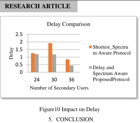
4.4. Impact on Delay
Figure 10 shows the comparison of Shortest Spectrum Aware and Shortest Delay Aware Routing Protocols in terms of Delay with increasing number of secondary users from 24 to 36 at a step size of 6. Shortest Delay aware is based on minimizing delay [21]. Figure 9 shows that for the first case, delay is lower or even constant but for the second case, it is decreasing gradually.
90 92 94 96 98 100
24 30 36
P
DR
Number of Secondary Users
Packet Delivery Ratio Comparison
Shortest_Spectrum Aware Protocol
Delay and Spectrum Aware
ProposedProtocol
0 200 400 600 800
24 30 36
T
h
ro
u
g
h
p
u
t
Number of Secondary Users
Throughput Comparison
Shortest_Spectrum Aware Protocol
Delay and Spectrum Aware ProposedProtocol
4.5 5 5.5 6 6.5
24 30 36
No
.
o
f
Ho
p
s
Number of secondary Users
Hopcount Comparison
Shortest_Spectrum Aware Protocol
RESEARCH ARTICLE
Figure10 Impact on Delay
5. CONCLUSION
This paper considers minimizing Delay keeping the shorter route and hence, presents a routing scheme that is efficient in terms of Delay. Table 3 shows the overall comparison and following important inferences can be drawn as follows:
The proposed protocol has high value of PDR in comparison to the shortest spectrum aware routing scheme.
The value of throughput and hop count is almost same in both of the schemes.
Value of delay is gradually decreasing in proposed delay aware routing but unpredictable in shortest spectrum aware routing.
Routing Scheme Metrics
Shortest Path Delay Aware Routing Scheme
Shortest Path Spectrum Aware Routing Schemes
PDR High Low
Throughput Same Same
Hop Count Same Same
Delay Low High
Table 3 Overall Comparison Table
REFERENCES
[1] Priya Goyal, Avtar Singh Bhuttar,” A study on 5G evolution and
revolution” published in International Journal of Computer Network and Applications, IJCNA-2015, Vol.-2(2), pp. 106-112.
[2] Akyildiz, W.-Y. Lee, and K. Chowdhury, "CRAHNs: cognitive radio
ad hoc networks," published in Ad Hoc Networks (Elsevier), 2009, vol.6, pp. 810-836.
[3] Mitola, J., Maguire, G.Q., “Cognitive radio: making software radios
more personal”, published in Personal Communications, 1999, vol. 6(4), pp.13–18.
[4] Ying–Chang Liang, Kwang Cheng Chen and Geoffrey, "Cognitive
Radio Networking and communications: An overview", published in IEEE Transactions on Vehicular Technology, 2011, vol. 60(7), pp.3386-3407.
[5] F. Akyildiz, B. F. Lo, and R. Balakrishnan, "Cooperative spectrum sensing in cognitive radio networks: A Survey," published in Journal of Physical Communication (Elsevier), PHYCOM-2011, Vol. 4(1), pp. 40-62.
[6] Pradeep Kyasanur and Nitin H. Vaidya, “Protocol Design Challenges
for Multi-hop Dynamic Spectrum Access Networks,” published in IEEE International Symposium on New Frontiers in Dynamic Spectrum Access Networks, 2005, pp.645-648.
[7] Cheng, W Liu, Y Li and W Cheng, “Spectrum aware on-demand routing
in cognitive radio networks”, published in 2nd IEEE International Symposium on New Frontiers in Dynamic Spectrum Access Networks, DySPAN-2007, pp. 571-574.
[8] G Cheng, W Liu, Y Li and W Cheng, “Joint on-demand routing and
spectrum assignment in cognitive radio networks”, published in the International Conference on Communications, ICC-2007, pp. 6499-6503.
[9] H Ma, L Zheng, X Ma and Y Luo, “Spectrum aware routing for
multi-hop cognitive radio networks with a single transceiver,” published in
the 3rd International Conference on Cognitive Radio Oriented Wireless
Networks and Communications, CrownCom-2008, pp. 1-6.
[10] Z. Yang, G. Cheng, W. Liu, W. Yuan, W. Cheng, “Local coordination
based routing and spectrum assignment in multi-hop cognitive radio networks”, Mobile Networks and Applications-2008, Vol-13(1-2), pp.67–81.doi: 10.1007/s11036-008-0025-9.
[11] Kiam Cheng How, Maode Ma, and Yang Qin,”An Opportunistic
Service Differentiation Routing Protocol for Cognitive Radio Networks”, published in the proceedings of IEEE Globecom-2010.
[12] Rana Asif Rehman, Muhammad Sher, Muhammad Khalil Afzal,”
Efficient Delay and Energy based Routing in Cognitive Radio Ad Hoc Networks”, published in the proceedings of IEEE conference-2012.
[13] Rana Asif Rehman and Byung-Seo Kim,”L2ER: Low-Latency and
Energy-Based Routing Protocol for Cognitive Radio Ad Hoc Networks”, International Journal of Distributed Sensor Networks, Vol.-2014.
[14] Zamree Che-Aron, Aisha Hassan Abdalla, Khaizuran Abdullah,Wan
Haslina Hassan, MD. Arafatur Rahman,” RACARP: A Robustness Aware routing protocol for cognitive radio ad hoc networks”, Journal of Theoretical and Applied Information Technology-2015, Vol.-76(2).
[15] El Masri, "A fuzzy-based routing strategy for multihop cognitive radio
networks", published in International Journal of Communication Networks and Information Security, IJCNIS-2011, Vol. 3(1), pp.74–82.
[16] Shailender Gupta, Bharat Bhushan and Vivek Kukreja, “A Fuzzy based
routing Protocol for Cognitive Radio Networks”, published in International Journal of Fuzzy Computation and Modelling (Inderscience-2014).
[17] Kamruzzaman, S.M., Kim, E. and Jeong, D.G., "An energy efficient QoS routing protocol for cognitive radio and ad hoc networks",
published in 13th International Conference on Advance
Communication Technology, ICACT – 2011, pp.344–349.
[18] F. Tang, L. Barolli, and J. Li, “A Joint Design for Distributed Stable
Routing and Channel Assignment Over Multi-Hop and Multi-Flow Mobile Ad Hoc Cognitive Networks”, IEEE Transactions Industrial Informatics, 2012, Vol. 10(2), pp. 1606-1615.
[19] Anitta Patience Namanya and Jules Pagna-Disso," Performance
Modelling and Analysis of the Delay Aware Routing Metric in Cognitive Radio Ad Hoc Networks", published in the proceedings of
6th joint IFIP Wireless and Mobile Networking Conference,
WMNC-2013, pp. 1-8.
[20] Vivek Kukreja, Shailender Gupta, Bharat Bhushan and Chander Kumar,
"Towards Performance Evaluation of Cognitive Radio Network in Realistic Environment", published in International journal of communication networks and information security, IJCNIS-2014, vol.6, no.1, pp.61-77.
[21] Poonam Mittal, Sanjay Batra and C.K. Nagpal,” Implementation of a
novel protocol for Coordination of nodes in Manet”, published in International Journal of Computer Network and Applications,
IJCNA-2015, Vol.-2(2),pp.99-105.
0 0.5 1 1.5 2 2.5
24 30 36
De
lay
Number of Secondary Users
Delay Comparison
Shortest_Spectru m Aware Protocol