Design of parallelized HDWT Hardware Architecture with
an Increased Throughput
James Ntaganda
Engineering Faculty Staff, University of Rwanda, College of Science and Technology Kigali, Rwanda PhD Candidate at Konkuk University, Electronic Engineering Department, Seoul-Korea
ABSTRACT
Discrete Wavelet Transform-based applications such as Multimedia CODECs require intensive computation. With modern technologies, Hardware-Software Co-designing has become a common practice. Such designs are regarded as SoC (System on Chip), where designers dedicate hardware modules for computational-intensive functions and are called routinely by the main program code, which is why they are called hardware accelerators. Comparatively, multiplication operation takes longer, consumes more processing power and utilizes more hardware resources. Keeping other factors constant, any technique that can reduce multiplication operations is considered a better approach in hardware designs. This paper is based on our previous published concept, where we exploited the simplicity of Haar function and proposed a recursive structure of a non normalized Haar Discreet Transform. We implemented it as a multiplier-less Haar DWT (HDWT) hardware module which can spatially transform 16x16 arrays. However, in our previous work, most of the processing nodes remained idle and exhibited less throughput. To increase parallelization and hence throughput, in this paper we propose “mirror-reflection” approach. This reduces the number of redundant and idle processing nodes in the circuit module and makes the circuitry scalable. With this approach, circuit redundancy was reduced and circuit utilization efficiency increased from 47% to 69%. The scalable hardware Module is implemented using FPGA.
General Terms
Signal processing, Hardware design, Multimedia compression
Keywords
Haar DWT, Image Compression, Hardware Implementation, Mirror-reflection, FPGA
1.
INTRODUCTION
Images and video clips are becoming our daily basis for information sharing and storage. Such growing demand, enormous binary information in multimedia content, scarcity of bandwidth and storage memory requirements dictate techniques for video compression [1]. Compression is done by means of trade-off. The video or image quality is traded-off to transmission and storage media gains. However, depending on applications, such a trade-off has to be done by preserving a considerable perceptual video quality for HVS (Human Visual Systems). In most of multimedia compression processes, CODECs will have to involve spatial/temporal Transformations, Quantization and information source coding from encoder side while the reverse is done in decoding process [1],[6], [9]. Discrete Wavelet Transforms have proved to be competitive in MJPEG2000 and its latest version such as MJPEG-XR and MJPEG-LS [6]. MJPEG2000 CODEC and
Cosine Transforms (DCTs), DWT features progressive image transmission by quality or resolution, lossy and lossless compressions, region of interest (ROI) encoding, and good error resilience [10]. Yusong Hu, Viktor K. Prasanna [14] emphasise that MJPEG latest standard series have chosen DWT instead of DCT due to its good energy compaction and inherent multi-resolution image presentation ability. Dragomir El Mezeni et al [6], describe JPEG-XR architecture in detail. Similarly, Christian Perra [7] suggested two architectures of MJPEG2000 and MPEG-XR, both of which deploy DWT at their transformation stage. Such Transformations require intensive computation, consume more power and occupy larger area on chip in hardware designs. In this paper we use the Haar DWT (HDWT) developed in our previous work [1] and design a “mirror-reflected” structure of non normalised Haar discreet transform. This is done with an aim of increasing the throughput as well as reducing circuitry redundancy and idleness. Thus, we increase circuit utilisation efficiency. The designed circuit structure can process arrays which may represent a video or an image frame micro block. Similar approach can be used in customizing designs to larger or smaller modules depending on the size candidate micro blocks to be processed. The rest of this paper is organized as follows: section two gives a brief review of Haar DWT. Section 3 shows circuitry design details, section four shows more analysis of the circuit and section five presents conclusion.
2.
DISCRETE WAVELET TRANSFORM
Wavelets are mathematical tools that can allow a function to be described in terms of a coarse overall shape, plus details that range from broad to narrow [2]. Regardless of whether the function of interest is an image, a curve, or a surface, Wavelets offer an elegant technique for representing the levels of detail present [2]. For any spatial data of NxN dimensions, each of its rows and columns can be represented as a linear combination of averaged and detailed coefficients (matrix entries) [4]. A. Jensen and A. la [4] presents a thorough reading on Ripples in Mathematics the Discrete Wavelet Transform and their hierarchical decompositions. For more topics about Discreet Wavelet Transform [4] avails a good reading.
2.1
Haar Function, its Scaling and Shifting
Nature
, 1,0 1 Equation(1) 0, i j x elsewhere
1,0 1 / 2 1
( ) 1, 1 / 2 Equation(2) 2 0, x x x elsewhere
Using equations (1) and (2), by scaling and shifting, in our previous work [1], we used MATLABTM simulation to
generate Haar wavelet MRA (Multi-resolution Analysis) graphical representation. These graphical representations made it easier to comprehend equations associated with this design.
2.2
Haar Wavelet Transforms Function
and its Basis
All Images or video frames can be spatially represented in form of array vectors to store respective rows and columns of an NxM resolution [1]. In arrays where N=M, the whole image is stored in a square matrix representation. In [1], vector,
I
R
16 was represented in its basis functions. We can represent I(x) in terms of Haar wavelet coefficients by equation (3) [1]i,j i,j
i,j Z
(3)
I(x)=
<I,ψ >ψ
By using equations (1) and (2),
I
R
16 can be represented by equation (4) [1]0 0,0 1 0,0 2 1,0 3 1,1 4 2,0
5 2,1 6 3,0 7 3,1 8 4,0 9 4,1
10 5,0 11 5,1 12 6,0 13 6,1 14 7,0
15 7,0
=I φ +I ψ +I ψ +I ψ +I ψ +
I ψ +I ψ +I ψ +I ψ +I ψ +
I ψ +I ψ +I ψ +I ψ +I ψ +
I ψ
(4)
I
Using the scaling functions and shifting operations [1], we can obtain the wavelet components of
I
R
16. It follows that each wavelet coefficient in MRA and orthogonal basis representation is given by equations (5) to (20) in [1], represented in as equations (5) and (6) in this paper. In theseequations, the scaled and shifted function
ψ
i j, denotes the unity shifted version of mother wavelet along the intervals. Because of limited space in this paper, only I0 and I15 arepresented for a quick understanding of the design. For details about derivation and representation of I0 to I15, our previous
work [1] reserves a better reading.
1/16 2/16 0 1/16 3/16 4/16 2/16 3/16 5/16 6/16 4/16 5/16 7/16 8/16 6/16 7/16 9/16 8/16 9/
0 0 0,0 1 0,0
2 0,0 3 0,0
5
4 0,0 0,0
7
6 0,0 0,0
8 0,0 9 0,0
I = s φ (x)dx+ s φ (x)dx
+ s φ (x)dx+ s φ (x)dx
+ s φ (x)dx+ s φ (x)dx
+ s φ (x)dx+ s φ (x)dx
+ s φ (x)dx+ s φ (x)
10/16 16 11/16 12/16 10/16 11/16 13/16 14/16 12/16 13/16 15/16 16/16 14/16 15/1610 0,0 11 0,0
12 0,0 13 0,0
14 0,0 15 0,0
5 7
1 2 3 4 6 8 9 10 11 12 13 1
dx
+ s φ (x)dx+ s φ (x)dx
+ s φ (x)dx+ s φ (x)dx
+ s φ (x)dx+ s φ (x)dx
s +s +s +s +s +s +s +s +s +s +s +s +s +s =
4+s +s15 16
16
(5)
15
1/16 2/16
0 4,0 1 4,0
0 1/16
3/16 4/16
2 4,0 3 4,0
2/16 3/16
5/16 6/16
5
4 4,0 4,0
4/16 5/16
7/16 8/16
7
6 4,0 4,0
6/16 7/16
9/16
8 4,0 9 4,0
8/16
=
s ψ
(x)dx+
s ψ (x)(x)dx
+
s ψ
(x)dx+
s ψ (x)dx
+
s ψ
(x)dx+
s ψ (x)dx
+
s ψ
(x)dx+
s ψ (x)dx
+
s ψ
(x)dx+
s ψ (
I
1/16 9/16 11/16 12/1610 4,0 11 4,0
10/16 11/16
13/16 14/16
12 4,0 13 4,0
12/16 13/16
15/16 16/16
14 4,0 15 4,0
14/16 15/16
15 16
x)dx+
s ψ
(x)dx+
s ψ (x)dx
+
s ψ
(x)dx+
s ψ (x)dx
s -s
+
s ψ
(x)dx+
s ψ (x)dx=
16
..(6)
2.3
Matrix Representation of Transform
Equations
Using I0 to I15 equivalencies, all equations can be represented
0 1 2 3 4 5 6 7 8 9 10 11 12 13 14 15
1 1 1 1 1 1 1 1 1 1 1 1 1 1 1 1
6 6 6 6 6 6 6 6 6 6 6 6 6 6 6 6
1 1 1 1 1 1 1 1 1 1 1 1 1 1 1 1
-( ) -( ) -() -() -( ) -() -() -()
6 6 6 6 6 6 6 6 6 6 6 6 6 6 6 6
1 1 1 1 -(1) -(1) -(1
6 6 6 6 6 6
I I I I I I I I = I I I I I I I I 1 1
) -() -( ) 0 0 0 0 0 0 0
6 6 6
1 1 1 1 1 1 1 1
0 0 0 0 0 0 0 0 -( ) -( ) -() -()
6 6 6 6 6 6 6 6
1 1 -(1) -(1) 0 0 0 0 0 0 0 0 0 0 0 0
6 6 6 6
1 1 1 1
0 0 0 0 -() -() 0 0 0 0 0 0 0 0
6 6 6 6
1 1 1 1
0 0 0 0 0 0 0 0 -() -() 0 0 0 0
6 6 6 6
1 1 1 1
0 0 0 0 0 0 0 0 0 0 0 0 -() -()
6 6 6 6
1 1
-( ) 0 0 0 0 0 0 0 0 0 0 0 0 0 0
6 6
1 1
0 0 -() 0 0 0 0 0 0 0 0 0 0 0
6 6 0
1 1
0 0 0 0 -( ) 0 0 0 0 0 0 0 0 0 0
6 6
1 1
0 0 0 0 0 0 -() 0 0 0 0 0 0 0 0
6 6
1 1
0 0 0 0 0 0 0 0 -( ) 0 0 0 0 0 0
6 6
1 1
0 0 0 0 0 0 0 0 0 0 -() 0 0 0 0
6 6
1 1
0 0 0 0 0 0 0 0 0 0 0 0 -( ) 0 0
6 6
1 1
0 0 0 0 0 0 0 0 0 0 0 0 0 0 -()
6 6 0 1 2 3 4 5 6 7 8 9 10 11 12 13 14 15 s s s s s s s s * 7 s s s s s s s s
3.
HARDWARE DESIGN
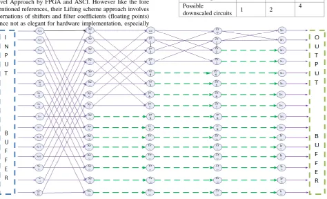
Yusong Hu and Viktor K. Prasanna [15], presented a good design for FPGA. However, in their design, they used two separate circuits to process rows and columns separately. Furthermore, they have used Parameterized Lifting-Based and involves multipliers. M. Nagabushanam [16] modified Distributive Arithmetic (DA) to avoid multipliers but their serialized shifters reduce the throughput of hardware modules which has to be used as hardware accelerator. Parvatham Vijay and Seetharaman Gopalakrishnan [17] presented a novel Approach by FPGA and ASCI. However like the fore mentioned references, their Lifting scheme approach involves alternations of shifters and filter coefficients (floating points) hence not as elegant for hardware implementation, especially
in digital circuit designs. Compared to other DWT, Haar is considered the more relaxed in terms of hardware design and exactly reversible without the edge effects faced with other wavelet transforms Khamees Khalaf Hasan [18]. Revisiting the conventional recursive architectures of FFT, DCT and DST, it was indeed possible to explore a better design for a Faster Discrete Wavelet Transform. By re-arranging 16 inputs elements of the candidate array, we were able to construct a recursive structure depicted in figure 1[1]. The major drawback of it is that the circuit processing nodes would remain redundant and hence hardware module remains underutilized. Contrary, by using “mirror- refection” approach, in this paper, hardware sharing and parallelization is possible, thus making our proposed structure better for multidimensional Image/video processing
3.1
Proposed Faster HDWT Structure
In this paper, we re-arrange the inputs starting with Sr for rowsof a matrix to be processed and Sc denoted re-arranged input
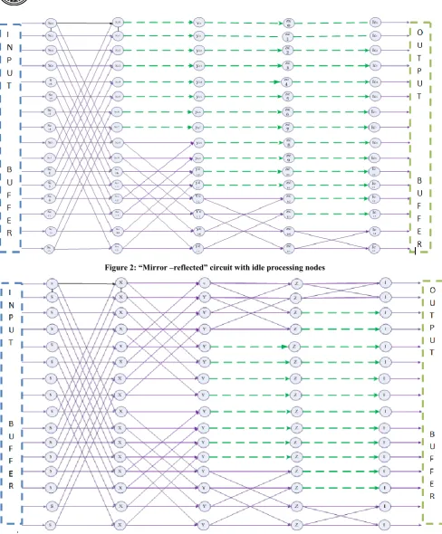
from columns of the same matrix. In both arrangements from the input buffer “n” ranges from 0 to 15 in a 16-array input. By imaginary (virtual) mirror reflection from the central axis of the circuit in figure1, futures 2 and 3 are re-drawn to represent reflected circuit and overall design respectively. This approach increased circuitry utilization efficiency Table 1. Possible downscaling circuitry combinations
Design 16x16 8x8 4x4
Possible
downscaled circuits 1 2
4
Figure 2: “Mirror –reflected” circuit with idle processing nodes
Figure 3: Overall circuit design with increased throughput and parallelization structure
buffer can be fed in to the input immediately. In so doing, the throughput can be increased. Contrary to our previous design, both columns and rows can be processed with only a time difference of one cycle. The only additional work in this design is pre and post re-arrangement of array elements to be processed. Judging from figures 1 and 3, it can be shown that the circuit utilization efficiency has increased from 47 % to 69%. This is depicted in table 2. It is worthy to mention in this section that circuit in figure 3 also allows the scalability of NxN arrays. For 16x16, there is only one possible
combination. On the other hand, if 8x8 array processing is required, there are two possible parallel circuits that can be found within figure 3. This can be done by bypassing S nodes and feeding the inputs to X nodes. Similarly, bypassing S and X nodes, 4 parallel circuitry can be achieved to process a 4x4 array. This is very important in video processing where different micro block sizes are processed separately based on region of interest and pixel homogeneity. These combinations are depicted in table 1.
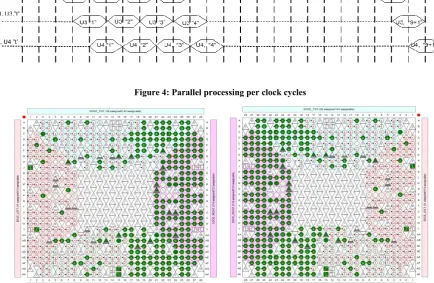
Figure 4: Parallel processing per clock cycles
(a) Tope view (b) Bottom view
Figure 5: Cyclone IV E-EPCE115F29C7 FPGA wire bonding
5.
CONCLUSION
In this paper, flexibility and simplicity of Haar Discreet Transform is Exploited to draw a recursive structure for a 16-element-array input. Due to redundancy of the processing nodes, a mirror-reflection approach is used. The hardware module is implemented Cyclone IV E-EPCE115F29C7 FPGA. Circuit Redundancy was reduced utilization efficiency increased from 47% to 69% compared to a “non-mirrored” module structure. The module can be used to Transform a
16x16 Micro block of a video frame with a high throughput by dual clock design. Furthermore where Scalable micro block processing is required, the input arrays can be down scaled from 16x16 down to 4x4. In the next work, we shall embed this hardware module into SoC systems for more advanced hardware-software co-design.
6.
REFERENCES
Relaxed Haar Discreet Wavelet Transform: Hardware module for Multimedia Compression. IOSR Journal of VLSI and Signal Processing (IOSR-JVSP)
[2] Chih-Hsien Hsia, et al. 2011 Memory-efficient architecture of 2-D lifting-based discrete wavelet transform, Journal of the Chinese Institute of Engineers [3] Eric J. Stollnitz, Tony D. DeRose, and David H. Salesin.
1995 Wavelets for computer graphics: A primer, part 1. IEEE Computer Graphics and Applications.
[4] A. Jensen and A. la Cour-Harbo. 2001 Ripples in Mathematics, the Discrete Wavelet Transform, Springer-Verlag.
[5] Jason Spielfogel, Why we like MJPEG compression, http://www.securityinfowatch.com/article/10561410/why -we-like-mjpeg-compression[Accessed on 4th may, 2015].
[6] Dragomir El Mezeni et el . 2010 JPEG-XR encoder implementation on a heterogeneous multiprocessor system, 5th European Conference on Circuits and Systems for Communications (ECCSC'10), Belgrade, Serbia.
[7] Cristian Perra .2013 Re-encoding JPEG images for smart phone applications, 21st Telecommunications forum TELFOR, IEE.
[8] Koichi Hattori, Hiroshi Tsutsui et al.2009. A High-Throughput Pipelined Architecture for JPEG XR Encoding, IEEE Conference Publications, IEEE Conference Publications.
[9] Harish Yagain, Srinivas Donapati.2011. Addressing the Interoperability Issues While Using JPEG-XR, International Symposium on Electronic System Design. [10]C. A. Christopoulos T. Ebrahimi and A. N. Skodras,
JPEG2000: The New Still Picture Compression Standard, Media Lab, Ericsson Research, Ericsson Radio Systems
AB, S-16480 Stockholm, Sweden.
[11]Saini, S. ; Mahajan, A. ; Mandalika, Implementation of Low Power FFT Structure using a Method Based on Conditionally Coded Blocks, IEEE Conference Publications 2010.
[12]]. JOHN E. SHORE. 1973. On the Application of Haar Functions , Concise Papers , IEEE TRANSACTIONS ON COMMUNICATIONS
[13]Iain Richardson, The new standard for video coding released by ISO MPEG and ITU-T VCEG http://www.vcodex.com/h265.html
[14]Zunera Idrees, Eliza Hashemiaghjekandi, Image Compression by Using Haar Wavelet Transform and Singular Value Decomposition, School of computer Science, Physics and mathematics Linnaeus University [15]Viktor K. Prasanna, Viktor K. Prasanna.2014 Energy-
and area-efficient parameterized lifting-based 2-D DWT architecture on FPGA, IEEE
[16]M. Nagabushanam P. Cyril Prasanna Raj, S. Ramachandran.2011. Design and FPGA implementation of modified Distributive Arithmetic based DWT-IDWT processor for image compression, Communications and Signal Processing (ICCSP), 2011 International Conference
[17]Parvatham vijay, Seetharaman Gopalakrishnan. 2013. Implementation of One Level 2D DWT Using Multiplier Less Modified Flipping Architecture, 2013 7th Asia Modelling Symposium , Hong Kong