130
Quadcopter Flight Dynamics
Mohd Khan
Abstract: Angular maneuvering scheme along with standard flight operations such as taking-off, landing and hovering is proposed for a quadcopter with indoor or outdoor flying capabilities. This is achieved by simultaneously controlling the speed of the four rotors in order for the quadcopter to attain the correct orientation. The total thrust is determined using the inputs of altitude, pitch and roll angles. Then the thrust that the rotors must generate independently is obtained from the ratio of the angles and the calculated thrust for maintaining the input altitude. Voltage supply that is needed to spin the rotors at a certain RPM (Rotations per minute) is obtained to produce the thrust computed in the previous step. Moreover, the procedure on varying the thrust direction of rotors is also illustrated to perform the standard flight operations.
Index Terms: Altitude, Quadcopter, Hover, Land, UAV, Orientation, Pitch, Roll, Rotor, RPM, Takeoff, Thrust, Velocity.
————————————————————
1 INTRODUCTION
A quadcopter is a popular form of UAV (Unmanned aerial vehicle). It is operated by varying the spin RPM of its four rotors to control lift and torque. The thrust from the rotors plays a key role in maneuvering and keeping the copter airborne. Its small size and swift maneuverability enables the user to perform flying routines that include complex aerial maneuvers. But for conducting such maneuvers, precise angle handling of the copter is required. The precise handling is fundamental to flying by following a user-defined complex trajectory-based path and also while performing any type of missions. This paper serves as a solution to handling the quadcopter with angular precision by illustrating how the spin of the four rotors should be varied simultaneously to achieve correct angular orientation along with standard flight operations such as taking-off, landing and hovering at an altitude.
2 PROCEDURE FOR PAPER SUBMISSION
2.1 Controlling a Quadcopter
A particular controller in the joystick is used to adjust the altitude. When the controller is moved up or down, the
propeller speed is adjusted causing the quadcopter to gain or lose altitude. This feature is used for taking-off/landing or fixing altitude while airborne. [2] Another controller is used to control the pitch/roll or angle of the quadcopter enabling it to move forward/back and left/right. Moving the controller to a certain direction increases the speed of the propellers in opposite relation to the direction the controller is pushed. [2] For instance, if the controller is pushed right, the left side propellers will speed up to tilt the quadcopter and cause it to move to the right. The words ‗quadcopter‘ and ‗copter‘ are used interchangeably throughout the paper. Sections 3.2, 3.3 and 5.1 give mathematical perspective of the aforementioned copter behaviors.
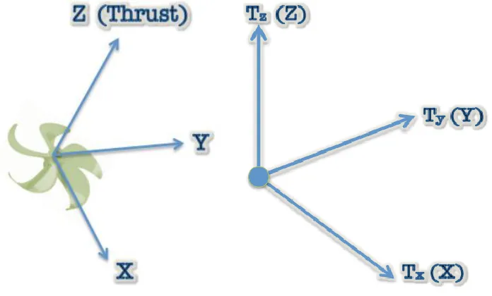
2.2 Inertial and Body frame
The inertial frame is defined with respect to the ground, with gravity pointing in the negative Z-axis. (Fig. 2) The body frame is defined by the orientation of the quadcopter, with the rotor pointing in the positive Z-axis and the arm-extensions pointing in the positive/negative X and Y axes. (Fig. 1) All metrics with respect to either the inertial or body frame are implied in braces. [4],[5]
3
THRUST
AND
STANDARD
FLIGHT
OPERATIONS
3.1 Thrust
Thrust is the force that is orthogonal to the propeller. [4],[5],[9] It is generated by rotor spin at a certain velocity (Eq. 1). Moreover, it accelerates the body in the direction of its force. In all the equations henceforth ‗i‘ refers to the particular rotor in Fig. 3
(Eq. 1)
In eq. 1, T is determined using the parameters v (velocity), ! (air-density) and A (cross-sectional area) of the propeller. A real-time air-density reading is necessary because the density of air is correlated to external environmental factors that are not always constant. As a result, the velocity of rotors required for the quadcopter to climb up or down, or hover a fixed altitude is also variable at external conditions. So, a constant air-density reading would dramatically compromise the performance of the rotors and therefore, the overall total thrust of the quadcopter. For the latter parameter, the crosssectional areas of all the propellers are constant during anystate of the flight. However, the area of the propellers could also contribute to the amount of total thrust generated.
3.2 Take-off and Land
In takeoff mode all the four rotors spin in CW direction. The CW direction contributes positive net thrust {Z-axis Body frame} on the quadcopter body, thereby enabling translational motion about positive Z-axis {Inertial frame}. [2],[4],[6] In landing mode all the four rotors spin in CCW direction. The CCW direction contributes negative net thrust {Z-axis Body frame} on the quadcopter body, thereby enabling translational motion about the negative Z-axis {Inertial frame}. [2],[6] Provided all the rotors are spinning in the same direction and velocity, Eq. 2 gives the net thrust on the body. [1],[6],[9]
(Eq. 2)
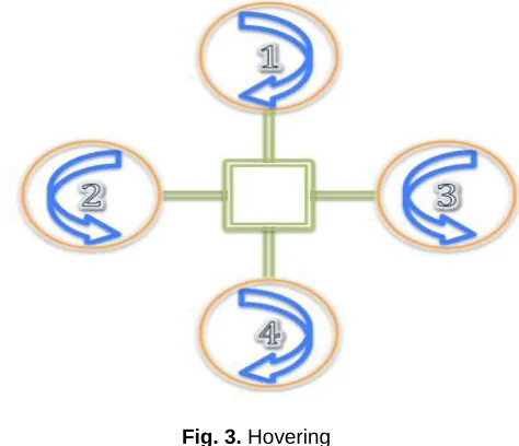
3.3 Hover
When the net thrust of all the rotors is equal to 0, the quadcopter maintains a state of constant altitude also known as hovering. The direction of rotation of a pair of rotors at each axis is always the same. For net thrust to equal 0, the spin direction of both rotors in X-axis {Body frame} must be opposite to the spin direction of rotors in Y-axis {Body frame}. [4] (Fig. 3) The speed of all four rotors during hovering is equal regardless of the propellers‘ direction of rotation. [1],[2],[6]
Fig. 3. Hovering
Eq. 3 shows the net thrust from the four rotors. [9] The arrows indicate the direction of thrust in the Z-axis {Body frame}.
(Eq. 3)
Furthermore, the net tangential acceleration is equal to 0 in sections 3.2 and 3.3. Therefore, translational motion is not observed in X and Y axes {inertial frame} during taking-off, landing or hovering.
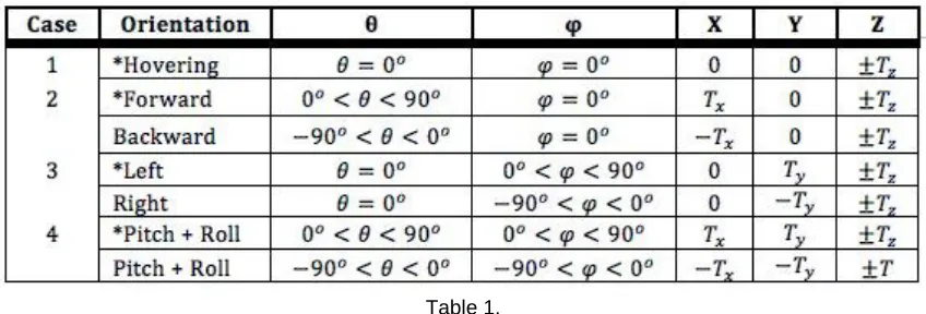
4 ORIENTATION
132 Table. 1 shows how the different orientations of the quadcopter are related to the range of angles for ! and !.
Table 1.
5
MATHEMATICALLY
DESCRIBING
THE
QUADCOPTER MOTION
5.1 Equations
From the law of conservation of energy we obtain Eq. 4, which is the velocity required for the quadcopter to climb from ho to any desired altitude of hf regardless of its angular orientation.
(Eq. 4)
Eq. 5 is the total thrust that is generated by the rotors in order to keep the quadcopter airborne at a certain desired altitude of hf given its total mass (m) and angular orientation (! and !).
(Eq. 5)
The magnitude of the total thrust from Eq. 6 is used to obtain the magnitude of the component vectors Tx, Ty, and Tz using Eq. 6, 7 and 8. The vector component magnitudes are with respect to the inertial frame.
(Eq. 6)
(Eq. 7)
A specific altitude can be maintained by total thrust from the rotors such that total Tz {Inertial frame} in Eq. 8 is constant.
(Eq. 8)
The thrust vector of the rotor can be obtained using Eq. 9 [5]
(Eq. 9)
The equations above are applicable only under the following circumstances: -
• The center----of----mass of the quadcopter is in the center of the body [5]
• Cross----sectional area of all the four propellers are equal
• The adjacent arm----extensions are perpendicular to one another [5]
• Angles ? and f should be less than 90o
5.2 Varying the speed of rotors
In section 4 we saw that a quadcopter must attain a certain angular orientation in order to be maneuvered. If the rotor speeds are variable, then such angular orientation is achieved where the speed of each rotor is independent. The ratio of thrust generated by the rotors is equal to the ratio of ! and !. (Eq. 10)
(Eq. 10)
Table 2.
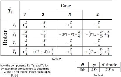
Table. 3 shows how the components Tx, Ty, and Tz for
thrust generated by each rotor are summed to determine the net vectors Tx, Ty, and Tz for the net thrust as in Eq. 9.
[1],[9]
Table 3.
The following sub-section demonstrates the use of equations in 5.1 and table. 2 and 3 in use for computing the required thrust of each rotor for arbitrary angle of ! and !.
5.3 Example
Arbitrary altitude of 2.5m and angles 30o, 25o for ! and ! respectively (Table. 4) are chosen for demonstration. Mass is assumed to be 1Kg and g = 9.8 m/s^2
Table 4.
Using the equations in section 5.1 the magnitude of component vectors Tx, Ty, and Tz and total thrust are calculated in Table. 5 The vectors are denoted as X, Y and Z. Product of air-density and propeller cross-sectional area is 1.
Table 5.
The thrust that each rotor must generate is calculated using the angle ratio (Eq. 10) to produce the correct orientation. Similar to Table. 3, the sums in Table. 6 show the magnitude of component vectors Tx, Ty, and Tz of thrust for individual rotor adds-up to the results in Table. 5 We also observe that 0.04m of altitude is lost during the defined state of copter position.
Table 6.
In order to validate the equations in section 5.1 we use the values of the vector components of thrust and calculate the pitch and roll angles using basic trigonometry (Fig 5). We use the information in Table. 6 to verify that the copter is
134 Fig. 5. Thrust vectors (Not to scale)
5.4 Evaluation
In Eq. 5 we saw that the total thrust is subject to change depending on ! and !. Fig. 6 is the graph of ! and ! vs. T. The graph illustrates that as the angles ! and ! increase the total thrust also increases. This is because more thrust {Z-axis body frame} is needed to keep the copter airborne.
Fig. 6. Graph 1
For the purposes of further evaluation we take samples of thrust for angles 30, 45, 60 and 75 (! and !) from Fig. 6. Fig. 7 is the graph of the mentioned angles vs. magnitude of Tx, Ty, and Tz. We observe that magnitude for the X and Y components increase as the angles increase. However, as expected the magnitude of the Z component of thrust is the same throughout.
Fig. 7. Graph 2
Table. 7 summarizes the graphs in Fig. 6 and Fig. 7. ‗c‘ is denoted as constant. The upward arrows denote ‗increase‘.
6 THRUST AND VOLTAGE
Brushless motors are often used in quadcopter due to their higher efficiency, reliability and lesser maintenance costs. These motors are rated in Kv (RPM/volt), also known as motor constant. We use the thrust needed from Table. 2 in
Eq. 12 gives the voltage needed for a motor to rotate at certain RPM equivalent to the linear velocity in Eq. 11. [4] ‗r‘ is the radius of the propeller.
(Eq. 12)
7 CONCLUSION
This paper presents a way to adjust thrust of the rotors via voltage supply to perform standard flight operations and to position the quadcopter into certain angular orientation depending on the circumstances of a particular flight routine. Moreover, it also illustrates the different behaviors of the copter mathematically that might be observed within a rangeset of angles. Total thrust is determined by the user-defined altitude and angles ! and !. Then the ratio of total thrust depending on the angle ratio is used to find the thrust for each independent rotor that is needed to calculate the voltage supply for the required RPM. The solution lays the foundation for further use in control scheme to develop a way to autonomously control the copter for flight stability and precision maneuvering when following a flight path.
8 REFERENCE
[1] Hoffmann, G.M.; Rajnarayan, D.G., Waslander, S.L., Dostal, D., Jang, J.S., And Tomlin, C.J. (November 2004). ""The Stanford Testbed Of Autonomous Rotorcraft For Multi Agent Control (Starmac)"". In The Proceedings Of The 23rd Digital Avionics System Conference. Salt Lake City, Ut. Pp. 12.E.4/1–10.
[2] Büchi, Roland (2011). Fascination Quadrocopter.
[3] ―Arducopter ---- Arduino----Based Autopilot For Mulirotor Craft, From Quadcopters To Traditional Helis ---- Google Project Hosting"". Code.Google.Com.
[4] Ashfaq Ahmad Mian, Wang Daobo (2007). ―Nonlinear Flight Control Strategy For An Underactuated Quadrotor Aerial Robot‖ Networking, Sensing And Control, 2008. Icnsc 2008. Ieee International Conference. Sanya, China
[5] Jun Li, Yuntang Li (2011). ―Dynamic Analysis And Pid Control For A Quadrotor‖ 2011 International Conference On Mechatronics And Automation.
[6] Matilde Santos, Victoria López, Franciso Morata (2010). ―Intelligent Fuzzy Controller Of A Quadrotor‖ 2010 Ieee Journal.
[7] Imu With Kalman Filter. Retrieved July 3, 2014, From Http://Cog.Yonsei.Ac.Kr/Quad/Quad.Htm.
[8] Mechanical Design. (2010, April 13) Http://Wyvernupenn.Blogspot.Ca/2010/04/Mechani cal-Design.Html.