Study Of Power Thermoelectric Generator By
Using Combustion Engine Heat Source
M.H. Muhammad Hafiz, M.H.Nuraida, O. Norzalina, A.B. Noorhelinahani, A.J.Julaida
Abstract: Energy harvesting has been surprisingly increased in the research and development until this day. The cause for the demand of renewable energy harvesting is rising due to the facts that fossil fuel is on the verge of being depleted. Currently, there are many ways to collect this infinite energy. One of the ways is by harvesting power thermoelectric generator by using combustion engine heat source. The main purpose of thermoelectric generator (TEG) is to provide the electricity supply to user by supplying the clean voltage in dc form without wasting the energy. There many applications of that can implement this method, for example the place that does not have main power supply. The (TEG) can use to support the electrical part for example to light up the lamp, to supply to battery charger for hand phone and many more. This project is very economical and low cost, which focuses to harvest heat source from combustion car engine which can reduce the usage of main battery of the vehicle and electricity.
Keywords: TEG concept, charger battery, engine car, produce electricity
————————————————————
1.
INTRODUCTION
A thermoelectric generator is a device that converts temperature differences into electrical energy called the Seebeck effect. In Seebeck effect theory, the electrons in the semiconductor act as transferring agent to transfer the heat from one medium to another medium according to the law of thermodynamics. By applying the Seebeck effect theory, this project had been proposed to design a device that generates electricity using combustion engine heat sources. The design of this project is to generate electricity which the heat source from combustion engine. In my project is to convert heat energy to electrical energy that can be used in battery. The heat energy that produce from engine and exhaust will be used to charge the battery (12V). The device that been used to make this generating system works is peltier TEG (Thermoelectric generator) device. In this project, it only covers on heat recovery system design, how to maximize the power generated from it and fabrication part of heat recovery system. The heat recovery system will be mount on the part of engine of Proton Wira and after data collection, there is some energy analysis regarding the power of electric generated from the heat recovery system.
1.1 Problem statement
The problem statement of this project how to develop energy generator that can be store in the battery and what effect the application of different size of peltier TEG and what good design for thermoelectric generator that give better efficiency.
1.2 Objective
A method has been proposed in order to overcome this problem. The objectives of these project is to design the thermoelectric generator charger to charge battery. Second objective to develop the thermal performance of thermoelectric effects using heat sources from combustion engine. Third to analyze the efficiency of generating electricity by using peltier.
1.3 Scope
The scope of this project is to study on the potential of peltier in generating electricity using heat resources. The project is to develop a generating system by using the best peltier in generating electricity. Data will be analysing in term of power, current and efficiency. The scopes of this
project is Focused how get voltage, current and power by using combustion engine heat sources and to analyse the Thermoelectric effect by Peltier module and do analysis.
2.0 LITERATURE REVIEW
This chapter explains about some of the literature reviews that are related to this project on the study of power thermoelectric generator by using combustion engine heat sources. This chapter also reviews the whole project for the purpose of gaining data, knowledge and skills required to complete this project. Different thesis sources are being used as guidelines for this project.
2.1 Thermoelectric generator
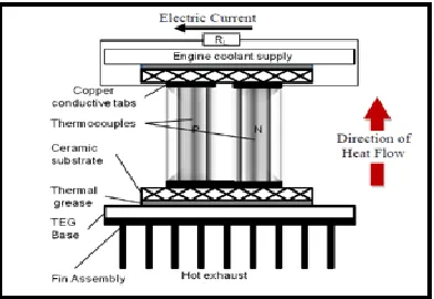
Thermoelectric generator is a device which converts available waste heat from an automobile exhaust into electricity using the Seebeck Effect as shown in Figure 1. The main components of these devices are a hot side heat exchanger, a coolant and cold side heat exchanger system, thermoelectric materials packaged as modules and a bypass system. The bypass system is required for scenarios when the exhaust gas exceeds the maximum allowable temperature for the safer operation of the thermoelectric modules. The hot side heat exchangers are either exhaust gas based or coolant based. The exhaust gas based TEGs convert the available waste heat from the exhaust gas of the internal combustion engine into usable electricity. Similarly, electricity.(Kumar, 2014)
92 2.2 Hot side heat exchanger
The hot exhaust gas from the automobile engine flows through the thermoelectric generator. The working fluid is a mixture of unburnt fuel, oxides of carbon, sulfur and remaining nitrogen. Here, the fluid can be modeled as a hot air without much loss in generality. The heat transfer through air poses a big constraint due to limitation of poor heat transfer coefficient. Desirable heat transfer is achieved by effective design of heat exchanger system. There could be several choices of commercial heat exchangers. However, plate fin based heat exchanger was preferred for the current design analysis due to its simplicity in design and modeling. In a plate fin heat exchanger, adding large number of fins could be helpful in augmenting high heat transfer rates but at the same time dangerously poses a risk of high back pressure rise which affects the fuel economy and engine performance. effectiveness.(Astrain & Martínez, 2012)
2.3 Thermoelectric generator working principles Thermo-electric generator (TEG) consists of thermo-electric module that functions to convert heat energy to electricity. This module has a flat surface and one side of this flat surface will act as heat source and the other side of surface is for heat sink. In this working principle, heat source is surface that function to absorb heat from system, for example in this case, exhausts system. Heat from exhaust pipe line will be absorbed by the Thermo-electric module through heat exchanger. Meanwhile at the heat sink, cooling system will creates at this flat surfaces thus down the temperature surface..(In & Lee, 2016)
2.4 Thermoelectric couple
Figure 2 depicts a schematic of a typical thermoelectric couple. The n-type and p-type thermoelectric legs are sandwiched between copper conductive tabs. These copper tabs complete the electric circuit when connected to an external electrical load resistance. These tabs are attached to ceramic substrates such as Alumina (Aluminium Nitride).Ceramic substrates are good heat conductor and excellent electrical insulators. Hence they facilitate heat transfer across the intermediate junctions and prevent any electrical current leakage. The hot side of the thermoelectric couple is kept in contact with the thermoelectric generator and heat exchanger assembly using commercial thermal grease to reduce thermal interface resistance. The cold side is in thermal contact with the engine coolant supply which is maintained at constant temperature of 100˚C. A plate fin type heat exchanger is integrated into the TEG to enhance heat transfer from the hot exhaust gas to hot side of Thermoelectric (TE) couples. The plate fin assembly contact resistance depends on integration and is not considered in current model.
Figure 2: Schematic of a thermoelectric couple
3.0 METHODOLOGY
3.1 Experiment setup
In this research, the research and idea to use the Peltier in to a Thermal Electric Generator (TEG). The main focus is peltier, by using Heat can create PE (Power Energy). In my project is to convert heat energy to electrical energy that can be used in battery. The heat energy that produce from engine and exhaust will be used to charge the battery (12V). The development of this project involve test the (TEG) concept into application. This project involve calculation and material selection. The methodology involve analyzing, designing, processing, block diagram, flow chart, other so that the methodology will understanding according following step given. This is to see the effect on all overall system application. Applying two different types of data for the overall efficiency, the temperature difference across the thermoelectric generator and the conversion efficiency. This to carry out an experimental study of a thermoelectric conversion unit consisting plate heat exchanger. In order to validate the results. This methodology to show of process from understanding to project completed.
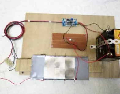
Figure 3: Experiment setup peltier for engine
3.2 Flowchart
Figure 4: Flowchart
3.3 Peltier teg
When DC voltage is applied to the module, the positive and the negative charge carriers in the pellet array absorb heat energy from one substrate surface and release it to the substrate at the opposite side. The surface where heat energy is absorbed becomes cold: the opposite surface where heat energy is released, become hot. Reversing the polarity will result in reversed hot and cold side. By applying the protection around peltier and cable so that the device be protected.
Figure 5: Peltier TEG
3.4 Proteus software
The Proteus Design Suite is a proprietary software tool suite used primarily for electronic design automation. The software is used mainly by electronic design engineers and technicians to create schematics
Figure 6: Schematic diagram for charging circuit
3.5 Fritzing software
Based on the Figure 7, Fritzing is an open-source hardware initiative that makes electronics accessible as a creative material for anyone. So, this software are using for design electronic part of this project.
Figure 7: Electronics circuit
3.6 Hardware development
This is the complete circuit that been done where the voltage regulator, circuit on PCB board, battery and output load been put together.
94
4.0 RESULTS & DISCUSSION
This chapter is implementation or testing phase which is the project or design shall to test. The project or design shall to test whether it you can energize as function as well or not. On this chapter also describe the complete prototype and compare with the initial propose. This project Implementation is consists of 2 which are Pre-Test Run and Result Test Run.Pre-Test Run its purpose to check the functionality of the peltier not connects the output. Just to test the ready of the peltier .While it on produce the output voltage is suitable value match with the output used.The measure that use volt meter for check the output add voltage/current during heating together with was attached. Test Run it purposes to check the finished desertion such over the connection, output and the others. The instrument used is Volt meter for checking all continuity in the circuit and make sure all the connection each terminal in the exact connection. List the project design was successful function as the planned. The result should be taken and analysis the voltage, temperature, current, watts. The result will show on tablet and graph.
3.7 Using 2 peltier
The table 1 show the result of performance for 2 plate peltier in terms of voltage, current and temperature difference. The maximum temperature is 430 Celsius and maximum voltage is 1.2v. Maximum current will get 0.9 ampere
Table 1: Result for using 2 peltier
3.8 Using 4 peltier
The table 2 show the result of performance for 4 plate peltier in terms of voltage, current and temperature difference. The maximum temperature is 420celcius and maximum voltage is 3.4v. Maximum current will get 1.7 ampere.
Table 2: Result using 4 peltier
3.9 Using 6 peltier
The table 3 show the result of performance for 6 plate peltier in terms of voltage, current and temperature difference. The maximum temperature is 440 celcius and maximum voltage is 5.2v. Maximum current will get 2.7 ampere.
Table 3: Result using 6 peltier
Calculation for power;
V = 5.2volt I = 2.7 ampere
Pw = V x I = 14.04 watts
According from figure 9 show the graph voltage vs time from method 1,2 and 3 will get increase voltage.
Figure 9: Graph of voltage vs time
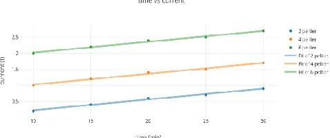
According from figure 10 show the graph time vs current from method 1,2 and 3 will get increase current.
Figure 10: Graph of time vs current
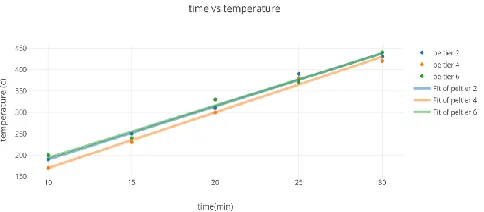
Figure 11: Graph of time vs temperature
Every peltier modules is designed to compromise several of performance objectives. Since TE modules operate through the interplay of electrical currents and thermal currents, the interaction with environment is as important as the electrical load. Therefore, the suggested experiments are carried out. An electrical power will be produced when the thermal reservoirs can achieve and maintain the maximum temperature. The large number of thermoelectric elements inside peltier will produce more electric. With relatively high voltage and low current. The relatively low current means that there are minimal internal losses due to Joule heating in the thermoelectric elements. The tall elements are desirable to maintain the temperature different due to relatively high internal thermal resistance between the hot sides. All method have been successfully tested. The data measurements have been collected every 10 minute using multimeter,voltage regulator and volt meter. The thermoelectric generator by studying all the required components for it along with their working. After doing experiments we can conclude here that such type of systems of waste heat recovery are feasible and can be applied on large scale. Temperature of engine increases. Output Seebeck voltage increases with increase in temperature difference across the Peltier plate. Output voltage and current are in linear relation means with increase in voltage; current also increases but not in exact proportion. Output power increases with increase in temperature difference across the Peltier plate. In this way by increasing power output we can increase the overall efficiency of the engine.
4.0 CONCLUSION
This project is purposely and supposedly to provide the new energy that suitable and available to produce the output voltage and can be apply to related output. The large number of thermo elements (n-type and p-type) in the peltier that are connected in electrical series thermal parallel, the high generated voltage will produce. The temperature different can generate voltage and when multiple the thermo elements the voltage can get higher using thermoelectric effect. The conclusion that see is thermal losses. The thermo losses between the hot on the peltier can make the current became low. The stable the current a good heat system needed in the Power Brick so that the output can produce higher power energy. The reason the application been make it because not many company or inventor try to develop the Thermoelectric generator (TEG) because they already other alternative way to generate voltage, but they didn’t know how use (TEG) affectively, all the finding and research been make
and hope that theory can success as practical after this. The reason this project to be develop, it’s because of using difference method especially using waste energy to get clean energy (voltage) Hopefully is expected to function so that it can be applied and added value for one of a renewable energy source. This project designed is the first model and still under research and needs to upgrade to applied. Hopefully this project also can be able and useful to applied everywhere such compact power energy and emergency energy actually for an electricity to ensure and encourage our electricity happy as the new system generate by purpose as new energy.
5.0 REFERENCES
[1]. Astrain, D., & Martínez, Á. (2012). Heat Exchangers for Thermoelectric Devices. Heat Exchangers - Basics Design Applications, (3), 289–308. https://doi.org/10.5772/33464
[2]. Gou, X., Yang, S., Xiao, H., & Ou, Q. (2013). A dynamic model for thermoelectric generator applied in waste heat recovery. Energy, 52, 201–209. https://doi.org/10.1016/j.energy.2013.01.040
[3]. In, B. D., & Lee, K. H. (2016). A study of a thermoelectric generator applied to a diesel engine. Proceedings of the Institution of Mechanical Engineers, Part D: Journal of Automobile Engineering, 230(1), 133–143. https://doi.org/10.1177/0954407015576440
[4]. Kumar, S. (2014). Thermoelectric waste heat recovery in automobile exhaust systems: topological studies and performance analysis, 1–48.
[5]. Rohini S. Mohite, Ansari nadir ajaz ahmed, & Khan Owais Ayyub. (2016). Thermoelectric Heat Recovery from Four Stroke Engine. Ijirct, 1(6), 511–515.