657 |
P a g e
A STUDY ON AIRFOIL CHRACTERISTICS OF A
ROTOR BLADE FOR WIND MILL
Dhatchanamurthy.P
1, Karthikeyan .L.M
2, Karthikeyan.R
3 1Department of Aeronautical Engineering, Kathir College of Engineering (India)
2
Department of Aeronautical Engineering, Techno Global University (India)
3
Department of Aeronautical Engineering, Er.Perumal Manimekalai College of Engineering, (India)
ABSTRACT
All over the world there is a substantial effort in design, development and installation of wind turbines for
renewable energy production. Aerodynamic design processes involved in the design of wind rotor for power
generation from wind. The design of airfoil shape of rotor blade is a most complex process for wind mill design.
This article aims to study on characteristics of an airfoil of a low power wind turbine blade for rural application in
domestic situation. As per the Betz,s theory, forces over a turbine segment has obtained and the airfoil
characteristics of a blade and it has analyzed using CFD software.
Keywords : Airfoil, CFD, Rotor Blade, Wind Mill
I. INTRODUCTION
The power from the wind is a natural source of renewable energy. In the present scenario, there is a perceived doom
arising from the complete utilization of non-renewable fossil fuels, the possibility of unlimited power hidden in the
natural wind provides a hope for the future. There are many efforts in design, development and erection of wind
turbine for generation of electrical power and connecting it to the local electric grid system. Design of large power
wind turbines for specific location assured of steady winds of high velocities, but the design of wind mills from the
range of 3 to 10 kilowatt (kW) for domestic and farms involves difficult processes. The effort in this study is for the
design of wind rotor of about 5 kW capacity of functioning in a wind of about 8 m/s. The emphasis here is in trying
to understand the main design issues and to design a rotor for the small-power turbine following the classical
method due to Betz.
II. GLOBAL THEORY OF WIND TURBINE DUE TO BETZ
The estimation of the wind power production capacity can complete using kinetics wind energy equation. Ali
Musyafa [1] explains a method to estimate the production capacity of wind turbines. The Rotor is used to extract the
power from wind. In practice the wind mill rotor will have certain number of blades placed equally around a hub.
Typically a high speed wind rotor will have three blades. Ali Musyafa and Ronny Dwi Noriyati [2] has indicated
658 |
P a g e
power obtained from wind can calculate from Betz’s law. Magdi Ragheb and Adam M. Ragheb [3] explain theglobal theory of wind turbine due to Betz. According to Betz’s simplified analysis, there is a limit to the maximum
value of power from a rotor and from oncoming wind. Fig 2 shows the wind turbine blade designed as per Betz’s
criterion.
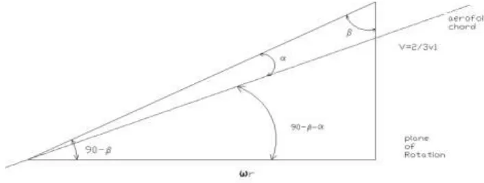
Fig 1: Velocity triangle at radius ‘R’ in relation to local airfoil
2.1 Design of a wind rotor: The design targets
In this study, a fast wind rotor for generating power of 5 KW has selected. For this high speed rotor we have three
blades. For such a wind turbine, based on Betz hypothesis that:
(1) Wind rotor is ideal, in the sense it has no hub and has an infinite number of blades which
offer no resistance or drag to the passage of air through it.
(2) The speed of air in front of it, at it and far behind is uniform across the cross sections.
(3) The velocity everywhere is purely axial, that is the component of swirl induced by the blades
is ignored.
(4) The individual blades, made of aerofoil sections, have no tip losses and no tip vertices are
shed.
Fig 2: Wind turbine blade designed as per Betz’s criterion; (a) Airfoil is NACA 23012, Design power = 5 kW, Tip speed ratio = 8, Wind speed= 7m/s, Blade diameter = 8.54 m; (b) 3 blade propeller with NACA 23012
659 |
P a g e
Under these assumptions, we can obtain the distribution of local chord of the blade aerofoil as a function of the localradius r, the number of blades n, and the rotor tip-speed-ratio λD
t (r)=2πR 1/n .8/9CL
Where CL is the lift coefficient corresponding to the max L/D for the aerofoil used.
2.2 Choice of The Aerofoil
There are many kinds of airfoils used for the design of wind-turbine rotor blades. Few examples are Gottingen 623,
NACA 4412, 4415, 4418, 23012, 23015 and 23018. Sandip. A. Kale and Ravindra N. Varma [4] has studied
aerodynamics design of a horizontal axis micro wind turbine blade using NACA 4412 profile.
Fig 3: NACA 23012 Airfoil
In this study we choose NACA 23012 airfoil for the rotor blade. In this case,
λD= /108.R/CL/ (r/R)2+1/154
λD=0.0291. R/CL/ (r/R)2+0.00649
For the NACA 23012 aero foil our CFD analysis shows a maximum L/D of about 53 corresponding to an incidence
of 8 degrees for which the lift coefficient is 0.96 using a value of CL=0.96, then the above equation becomes :
t (r) =0.0303./ (r/R)2+0.00649
Table 1: Distribution of t (r), β(r) and I as a function r/R
r/R t (r) meter β(r) degree (I) degree
0.0 1.54 0 82
0.1 0.9677 50.19 31.81
0.2 0.5763 67.38 14.62
0.3 0.4000 74.56 7.44
0.4 0.3046 78.23 3.77
0.5 0.2456 80.54 1.46
0.6 0.2057 82.09 -0.09
0.7 0.1762 83.21 -1.21
0.8 0.1545 84.05 -2.05
0.9 0.1375 84.71 -2.71
660 |
P a g e
2.3 Diameter ‘D’ of the rotor
This being the high speed rotor we use the thumb-rule P=0.20 D2 V3 to determine the diameter D for a given
wind speed V.
For our case P=5000 W,V=7m/s
i,e 5000=0.20 D2 73 or D=8.54m
For thin wind rotor t (r) is given by (for R=4.27m)
=0.1294/ (r/R)2+0.00649 (m)
From this we can compute t (r) as shown in the table 1.
Fig 4: (a) Aerofoil is placed between (0,0) and (1,0); 4 (b) Quadrilateral grids around the airfoil
with suitable clustering
2.4 Setting angle for the profiles
At any section r we have the velocity triangle shown in fig 1, under optimum or Betz,s condition.
= ωr/v =3/2 ωr/v1 =3/2 ωr/v1. (r/R)
=3/2 .λD (r/R)
Where by definition λD= ωR/v1, v1 being free stream velocity. For the present case λD=8 and we have
=12(r/R)
We can now compute β(r) as function of r/R as shown in the table 1.
Fig 5: (A) Close View Of The Grid Around Naca 23012 Aerfoil; (B) Close View Of The Grid At The
661 |
P a g e
As we can see from the velocity triangle β is the direction of the resultant velocity at the Plane of the rotor at aradius r. For its best performance the aero foil should take this free stream at an optimum incidence α, where L/D
is Maximum. We have chosen NACA 23012 as the aero foil and this aero foil has a maximum L/D of about 70
around an incidence of 8°, where the lift coefficient is 0.96. We choose the keep the incidence same for all the
sections although one may choose different incidence. With thin the following distribution of setting angles Z results
along the radius of the rotor blades. The table 1 shows the distribution of chord t (r), local flow angle with respect to
the flow direction β(r), setting angles (I) as a function r/R.
III. COMPUTATIONAL FLUID DYNAMICS
Thanks to the continuous developments in more and more powerful computers, with enormous speed and storage
capabilities, the field of Computational Fluid Dynamics (CFD) has now reached a stage of maturity where it is
claimed that it possible to do, routinely, computations to obtain simulation of complex flows over complex
geometries and for real-life flow situations -- very reliably and in a short time. Over the years the field of grid
generation has grown from simple rectangular body piercing grids to body conforming grids. There are also zonal
methods for grid generation for dealing with special set of geometry in given shape, overlapping grids and
unstructured grids. The field of grid generation has indeed grown into a fully mature field. We use in this study
FLUENT which is the flow code and the GAMBIT which is the grid generation code.
We have studied in this report the geometric parameters such as extent of domain for computations, the role of
relaxation parameters in the process of numerical convergence of numerical solution. Furat Abdal Rassul Abbas and
Mohammed Abdulla Abdulsada, [5] have studied the simulation of wind-turbine speed control using MATLAB. For
validation we have chosen baseline NACA 23012 aerofoil as a candidate since our study in this project concerns the
same aerofoil with split flap on it. This validation study contains comparison of basic aerofoil lift, drag vs. angle of
attack as a basis of validation. We have chosen standard experimental results available in literature. Based on this
study we fix up range of parameters for our investigation of flow over the split flap.
3.1 Characteristics of NACA 23012 as validation Exercise
Fig 3 shows NACA 23012 aerofoil and Table 1 contains standard coordinates. These coordinates are imported to
GAMBIT and quadrilateral grids are created over sub-domains into which the main domain of fluid flow hs divided.
The numerical flow domain taken for this study has shown in Fig.4 (a). The aerofoil is placed between (0,0) and
(1,0). The chord of the aerofoil is thus unity. Fig.4(b) shows the quadrilateral grids around the airfoil with suitable
clustering. Close view of the grid around NACA 23012 aerfoil as shown in fig 5(a). Fig 5(b) shows closely spaced
grid around leading edge close to the body in order to pick up rapid changes taking place in that region. In this
study, spalart allmaras one equation code has choose for model.
We have retained default options for parameters in the model and we have used second order upwind finite
differencing. In fluent for solving simultaneous equations, various iterative methods are available and that results
662 |
P a g e
that converging results are obtained with relaxation factor continuity x and y and turbulence viscosity has set as 0.3.We had chosen inherent choice as an available option in fluent. Fig 6 shows the lift and drag characteristics of basic
NACA 23012 aerofoil compared with Experimental values.
Fig 6: Lift and Drag characteristics of basic NACA 23012 aerofoil compared with experimental
values
3.2 Flow Simulation Versus Prediction Capabilities of CFD
Although considerable progress has been made in the field of computational fluid dynamics by the way of excellent
algorithms, of flow models for particularly turbulent flows as well as the equations of conservation laws of fluid
dynamics, very many software’s available in the literatures. In general fluid mechanics particularly that there is large
number of extraneous parameters peculiar to algorithm or to flow model, turbulent etc. one of the essential steps in
CFD namely the grid generation also would involve several parameters peculiar to geometry, some of these would
include the need for special grids around specific flow regions where flow gradients are high as well as peculiarity
of grids for capturing boundary layer. We would like to distinguish the simulation capabilities from predictive
capabilities of the given software. We mean by simulation capability the possibility of obtaining any experimental
results considered to be accurate but known as the time of computation.
In simulation, it may so turn out that on reasoning the code it’s just possible to mimic the experimental results. Often
663 |
P a g e
parameters space and after assessing that these will give the best results. One way use the code along with theparameter space for generating data for geometries quite close to the geometry use in simulation exercise to generate
useful practical results. In contrast to this if software were to have predictive capability, one should be able to obtain
good comparison with standard result with some default options for parameters in the code. While more and more
software achieving predictive capability there still some room for improving other codes in direction of CFD.
VI. CONCLUSION
The effort in this study is for the design of a low power wind turbine in the range of 3 to 10 kW. This contains the
CFD analysis of the aerofoil chosen for the blade and the procedure for the design of a wind turbine rotor. This is an
attempt to design a wind rotor of about 5 kilowatt capacity capable of functioning in a wind of about8m/s. This
study consists of Computerized Fluid Dynamics (CFD) analysis of the aerofoil chosen for the blade and the
procedure for the design of a wind turbine rotor. The procedure outlines the main issues involved in the
determination of the diameter and of the radial chord distribution for a three bladed horizontal axis wind turbine.
REFERENCES
[1] Ali Musyafa, Comparative Analysis of Small-Scale Wind Turbine Design for the Low Rate Wind Speed,
Asian Journal of Natural and Applied Sciences, 1(3), 2012.
[2] Ali Musyafa and Ronny Dwi Noriyati, Implementataion of Pitch Angle Wind Turbine Position for
Maximum Power Production, Academic Research International, 3(1), 2012.
[3] Magdi Ragheb and Adam M. Ragheb, Wind Turbines Theory - The Betz Equation and Optimal Rotor Tip
Speed Ratio, Fundamental and Advanced Topics in Wind Power, Intech Publication, 2011, 19-38.
[4] Sandip. A. Kale and Ravindra N. Varma, Aerodynamic Design of a Horizontal Axis Micro Wind Turbine
Blade Using NACA 4412 Profile, International Journal of Renewable Energy Research, 4(1), 2014.
[5] Furat Abdal Rassul Abbas and Mohammed Abdulla Abdulsada, Simulation of Wind-Turbine Speed
Control by MATLAB, International Journal of Computer and Electrical Engineering, 2(5), 2010,