Design and Analysis of Cylinder and
Cylinder head of 4-stroke SI Engine for
weight reduction
Ravindra R. Navthar 1
ravi_navthar@rediffmail.com Prashant A. Narwade 2
1 & 2 Asst. Prof. Dept. of Mechanical Engineering, P.D.V.V.P. College of Engineering Ahmednagar-414111, Maharashtra , India.
Abstract
The present paper deals with design of cylinder & cylinder head with air cooling system for 4 strokes 4 cylinder SI engine. The main objective of design is to reduce weight to power ratio & will result in producing high specific power. The authors have proposed preliminary design cylinder & cylinder head of a horizontally opposed SI engine, which develops 120 BHP and posses the maximum rotational speed of 6000rpm. Four stroke opposed engine is inherently well balanced due to opposite location of moving masses and also it provides efficient air cooling.
For the requirement of weight reduction the material selected for design of cylinder and cylinder head is Aluminum alloy that is LM-13. The cylinder bore coating using NIKASIL coating was done to improve strength of cylinder with minimum weight..
1.0 Introduction :
Horizontally opposed four stroke four cylinder si engine:-
A flat-4 or horizontally-opposed-4 is a flat engine with four cylinders arranged horizontally in two banks of two cylinders on each side of a central crankcase. The pistons are usually mounted on the crankshaft such that opposing pistons move back and forth in opposite directions at the same time. The general layout of this engine is shown in fig. 1
Fig 1. Layout of horizontally opposed 4 cylinders, 4 stroke SI Engine
design to manufacture, and somewhat too wide for compact automobile engine compartments, which makes it more suitable for cruising motorcycles and aircraft than ordinary passenger cars.
This is no longer a common configuration, but some brands of automobile use such engines and it is a common configuration for smaller aircraft engines such as made by Continental. Although they are somewhat superior to in-line 4stroke engines in terms of vibrations, they have largely fallen out of favour because they have two cylinder banks thus requiring twice as many camshafts as for in-line engines.
2.0 Material Selection
As means for reducing weight, there are several methods available substituting light weight materials for conventional materials, that is to decrease specific gravities, rationalization of structure (decrease the number of parts through integration), & downsizing (decrease the volume of each part).
In the past, the engine performance has been compromised in order to improve emission. The methods presented here, however are fundamentally different from the past one.
Fig 2. Material Composition of Weight-Reduced Engine & Base Engine [1]
The engine weight has reduced by 37 Kg from a base one of 162 Kg (excluding engine oil).This corresponds to 23% weight reduction. As shown in fig. 2 the component weight ratio of the materials are 53% steel for the weight-reduced engine (86% in the base engine), 33% (13%) Aluminum alloys, 7% (1%) plastics & elastomers, 6% (0%) other light weight materials such as titanium alloys & magnesium alloy, & 1% (0%) ceramics.
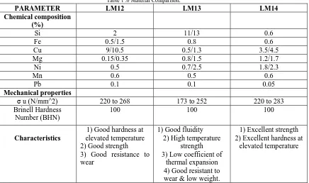
2.1. Material Comparison [1,4]
Table 1 .0 Material Comparison.
PARAMETER LM12 LM13 LM14 Chemical composition
(%)
Si 2 11/13 0.6
Fe 0.5/1.5 0.8 0.6
Cu 9/10.5 0.5/1.3 3.5/4.5
Mg 0.15/0.35 0.8/1.5 1.2/1.7
Ni 0.5 0.7/2.5 1.8/2.3
Mn 0.6 0.5 0.6 Pb 0.1 0.1 0.05
Mechanical properties
σ u (N/mm^2) 220 to 268 173 to 252 220 to 283
Brinell Hardness Number (BHN)
100 100 100
Characteristics
1) Good hardness at elevated temperature 2) Good strength
3) Good resistance to wear
1) Good fluidity 2) High temperature
strength 3) Low coefficient of
thermal expansion 4) Good resistant to wear & low weight.
1) Excellent strength 2) Excellent hardness at
elevated temperature
From above it is clear that, the material suitable for given application is LM-13. Because it has a low thermal coefficient also for further processing of coating on cylinder bore of this material is well suited.
2.2 Cylinder Bore Coating
The important parameters for light weight & high speed engine application are the selection of the material & the surface modification by hard coating on bore of cylinder block.
The strength to weight ratio has also become an important parameter for the design consideration as it has multiple advantages e.g. improved fuel efficiency, load carrying capacity etc. For the development of light weight cylinder block for air borne application, the use of cast iron liner has been replaced by hard coating technology on the cylinder wall surface. In INDIA the hard layer coating technology on Aluminum is found in application.
Following kinds of hard layer surface coating over Aluminum has been successfully achieved in foreign countries.
a) Nikasil (Ni + SiC composite coating) b) Hard chrome coating.
c) Apticoat 750 (Ni + Ceramic composite) developed by M/s SAT Poeton Ltd., UK for racing car.
a) Nikasil Coating [9]:-
TABLE 2. Improvement of engine performance by cylinder block material [9]
Material Sfc (gm/kw-hr) Thermal
conductivity (W/mk)
Weight (kg)
Cast iron 490 54 2.18
Aluminum barrel With cast iron sleeve
380 54-109 1.12
Aluminum barrel with NIKASIL plating
310 109 0.78
b) Hard Chrome Plating [9]:-
The hard chrome plating on cylinder block of Aluminum alloy is done through electroplating deposition. In this process cylinder blocks are made cathode & the anode, usually made of lead (Pb), acid solution. The dimension of the anode depends on the bore diameter & stroke length of cylinder block. The thickness of coating is controlled by knowing the total surface area of the cylinder bore & adjusting the current density. It has been reported that a coating thickness of 60-70 microns on bore surface of Aluminum cylinder block gives better fuel efficiency & thermal conductivity in comparison with Cast Iron cylinder blocks or Aluminum barrel fitted with Cast Iron liner.
Seleced Coating:-
NIKASIL coating is selected for coating of cylinder bore because it has got better performance compared to
hard chrome plating. Also NIKASIL coating has got hardness about 2500 VPN where as chrome plating has only 800-900 VPN.
3.0 Basic Engine Design 3.1- Design of Cylinder:
Table 3. Cylinder Dimensions
3.2 Cylinder Thickness Design
Thickness of Cylinder is 5 mm.
3.3 Cylinder Head Design:
Table 4.0 Cylinder Head Dimensions.
Deign Parameter Calculated values
Cylinder wall thickness t 5 mm Cylinder head thickness t’ 9 mm
3.4 Valve Spacing On Cylinder Head:-
Fig 3. Valve spacing diagram [2]
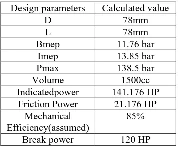
Design parameters Calculated value
D 78mm L 78mm
Bmep 11.76 bar
Imep 13.85 bar
Pmax 138.5 bar
Volume 1500cc
Indicatedpower 141.176 HP
Friction Power 21.176 HP
Mechanical Efficiency(assumed)
85%
Figure shows the empirical relation for inlet & exhaust valve spacing. Clearance between valve & bore = 2.3 mm
Space between valves (inlet & exhaust) = 9.36 mm
3.5 Inlet And Exhaust Manifold
Fig. 4. Inlet Manifold . Fig. 5. Exhaust Manifold .
3.6 Valve Seat:
Fig 6. Valve Seat design [6]
From figure we get the relation for valve seat outside diameter & height.
3.7.1 Inlet Valve Seat Design:-
Thickness of valve seat (t)i = 3.517 mm Height of valve seat (h)i 9.0558 mm 3.7.2 Exhaust Valve Seat Design:-
Diameter of valve seat (De):- 24.57 mm Thickness of valve seat (t)e = 3.003 mm Height of valve seat (h)e = 7.37 mm
Table 5. Dimensions of valve seats:-
PARAMETER
(mm)
INLET VALVE
SEAT
EXHAUST VALVE SEAT
D 30.186 24.57
t 3.517 3.003
h 9.0558 7.37
3.8 Design Of Cooling Fins
Material: - Aluminum alloy (Thermal conductivity =109 web/mK)
Table 6 Dimensions of cooling fins
Required parameter Calculated value
Root thickness of the fin, 3 mm
Space between two fins 3.96 mm
Number Of fins 24
4.0 Solid modeling of Cylinder
Fig . 7. Model of cylinder Fig. 8. Model of cylinder head
5.0 FEA ANALYSIS Of Cylinder And Cylinder Head
Table 7 Input parameters for analysis
PARAMETER VALUE
Maximum pressure 1.38e+007 N/m2
Maximum temperature 1032 K
Young’s modulus 7e+010 N/m2
Poisons ratio 0.34
Density 2700 Kg/m3
Thermal expansion 2.968 e-004 (1/K)
Yield strength 346e+008 N/m2
Fig. 10 Analysis of cylinder head
6.0 Conclusion
From the analytical solution & the analysis result we get the values of stresses produced in cylinder and cylinder head due to application of temperature and pressure are within permissible limit. Hence we concluded that the basic design of cylinder and cylinder head is safe with reference of pressure and temperature basis. Due to the use of light weight material i.e. LM-13 with NIKASIL cylinder bore coating, we can effectively reduce the weight of cylinder and cylinder head with improved strength. Also due to the use of air cooling system an efficient and faster cooling of engine achieved.
References
[1] Sae Paper ‘Weight Reduced Engine’(1992): Volume-101 “Journals Of Engine Section-3”
[2] Chrles Fayette Taylor- “The Internal Combustion Engine In Theory & Practice (Vol.2, Page No.- 425)”
[3] A Kolchin & V. Demidov – “Design Of Automotive Engines” (Page No.- 439)
[4] V.L.Maleev - “I.C.Engines” (Page No. – 310, 297)
[5] Colin R Ferguson - “The Internal Combustion Engine” (Page No. - 313)
[6] William H Crouse - “Automotive Engine Design” (Page No. - 218)
[7] Julius Mackerle - “Air Cooled Automotive Engines” (Page No. – 204)
[8] V.Ganesan - “I.C.Engines”, Second Edition, Pub: Tata Mcgraw Hill (Page No. 4-492)
[9] V.Ramanujachari - “Internal Combustion Engine & Combustion” (Page No. – 115,116)
[10] Sharma & Purohit - “Design Of Machine Element” (Page No. – 634,635)
[11] R.K. Jain - “Machine Design” (Page No.- 1214)

![Fig 2. Material Composition of Weight-Reduced Engine & Base Engine [1]](https://thumb-us.123doks.com/thumbv2/123dok_us/9642991.1492261/2.595.176.419.253.367/fig-material-composition-weight-reduced-engine-base-engine.webp)