CONICAL NETWORK RELATED
ISSUES IN VIRTUALLY MODIFIED
MULTI PROTOCOL LABEL
SWITCHING
SIDDHARTH SRIVASTAVA
M.Tech (Research Scholar) Department of Computer Science and Engineering, Madan Mohan Malviya Engineering College, Gorakhpur, Uttar Pradesh Technical University,
Lucknow, Uttar Pradesh, India
phone: 09455280244, email: [email protected] UMESH CHANDRA JAISWAL
(Associate Professor) Department of Computer Science and Engineering, Madan Mohan Malviya Engineering College, Gorakhpur, Uttar Pradesh Technical University,
Lucknow, Uttar Pradesh, India
phone: 0923550528, email: [email protected] MONIKA ARYA
(Head of Department) Department of Information Technology, Dr. M.C. Saxena College of Engineering and Technology, Lucknow, Uttar Pradesh Technical University,
Lucknow, Uttar Pradesh, India
phone: 09454517510, email: [email protected] Abstract:
This journal is based on conical network related issues which arises in virtually modified Multi Protocol Label Switching. Here in this journal first we will give an overview of protocol entitled Multi Protocol Label Switching. Then we discuss its virtually modified version which we have already fabricated. Finally we discuss the issues which came into light after the formation of conical network in virtually modified multi protocol label switching. In this journal we will take five important issues into account namely management, delay, communication, network distribution and overall performance. We discuss these issues with respect to conical network. The basic protocol of this research journal namely virtually modified multi protocol label switching (VMMPLS) is implemented in Dr. M.C. Saxena College of Engineering and Technology, Lucknow as live project. After reading this journal readers could understand that if size of conical network increases than performance of underline network decreases.
Keywords: conical network, data packet, control packet, virtually modified multi protocol label switching
1. Overview of Multi Protocol Label Switching (MPLS)
We are now going to discuss the basics of MPLS protocol. This protocol was designed by Internet Engineering Task Force (IETF) and its specifications were given in RFC 3031(Request for Comments). Now we are going to give the basics of this protocol next, in form of points.
b) Then whenever packet has to move inside the MPLS subnet then it enters from the ingress router and whenever any packet has to move out from the MPLS subnet then it moves out from the egress router (see figure 1).
c) Now whenever any packet has to move from source to destination through MPLS subnet then it is subjected to the ingress router first.
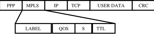
d) Then ingress router adds a tag or label which is known as MPLS label to it and switches it inside the MPLS subnet (See Figure 2).
e) Then using this MPLS label (Complete label format is shown in figure 3) this packed moves from one node to another within the MPLS network. Whenever this packet moves from one node to another then the node updates the MPLS header accordingly so it could easily be switched from one node to another until it don’t reaches the destination node or egress router. For example see figure 2 in this we have shown Label field of MPLS header according to it packet has to move from ingress router towards destination. Now when packet reaches to ingress router it adds an MPLS tag in it and switches it to node say A. Now this node A has a routing table in it whose partial version is shown in figure 2. Now from label field first digit is read which is index 1. This index is searched in the routing table of node A and packet is switched to node C which is correspondent node at index 1. Moreover MPLS header is also modified by node A as shown in figure 2.
A Ingress
Packet
Packet MPLS Header
1, 3, 5, 6, 7, DEST Label field of MPLS header
Partial Routing table of ‘A’ Packet is
switched at node ‘C’
3, 5, 6, 7, DEST Label field of MPLS header to ‘C’
Index Node Via
1 C -
2 B - … … …
Figure 2 showing that Ingress router adds MPLS header to incoming packet. It also shows Label field of MPLS header and how packet is moved from node ‘A’ to node ‘C’.
A
B
C
E
D
F Ingress
Egress Packet
Packet
f) If the destination node is present inside the MPLS network then ok. Packet is switched there.
g) But if destination node lies outside the MPLS network then packet reaches the egress router and there egress router removes the MPLS tag from it and routes the packet out of the MPLS network towards the destination.
This is basic working of MPLS protocol. Interested readers are suggested to read my research journal entitled “Virtually Modified Multi Protocol Label Switching” (See reference [1]) to get more details on basic idea of this protocol and its virtually modified versions. Here since our basic is to deal with conical network related issues so we are going to end the discussion of MPLS here.
2. Overview of Virtually Modified Multi Protocol Label Switching (VMMPLS) and Conical Network
We are now going to discuss our basic concept of Virtually Modified Multi Protocol Label Switching in short. Readers are requested to go through our research journal entitled Virtually Modified Multi Protocol Label Switching to get the depth of this topic (see reference [1]). This is because here we focus our discussion towards conical network related issues so we are not going to give the complete detail of the topic here. This is because if we do so then this journal will become the partial copy of our previous journal which we don’t want. But still here we give the ample of content by which readers could easily understand the concept in great detail.
In simple communication model it is observed that if we have to transfer data from one place to another then this communication takes place in three steps which are listed below.
Step 1: Establish communication or synchronization link between source and destination node. Step 2: Transfer the data from source to destination node.
Step 3: Transfer the acknowledgement from destination to source node.
Now in real world scenario what actually happens is that data transfer takes place in form of packets. Moreover synchronization is done in form of packets and acknowledgement is also transferred in form of packets. So the packets which are used for synchronization and acknowledgment purposes can be regarded as control packets and packets which contain data to be transmitted can be termed as data packets.
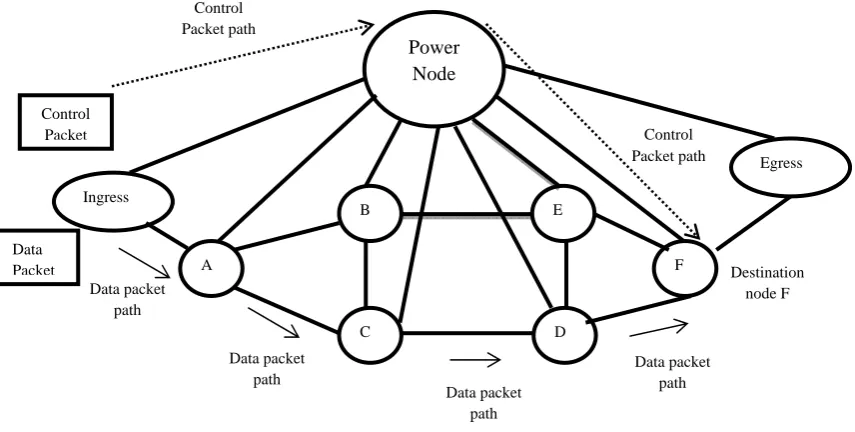
Now if one look these three steps which are given above then he could conclude that to transfer one data packet two control packets are used (one for synchronization and other for acknowledgement). Now if these packets (data packets and control packets) has to pass through MPLS subnet then although these packets are switched quickly using MPLS protocol in MPLS subnet but still MPLS subnet is having more control packets in comparison with data packets. Now one could easily see that these control packets produces more congestion in underline MPLS network in comparison with data packets. Now what we did is that we have added additional node namely power node in MPLS subnet which is having several properties as listed below. Using this power node we switch control packets and data packets are switched using MPLS network. Properties of Power Nodes are listed below.
(1) Power node is connected to each and every node present in the MPLS subnet which is allotted to it. (2) Power node provides communication between any two nodes of MPLS network just in one pass (i.e.
packets travels from source to power node to destination).
(3) Power node is imparted with high amount of bandwidth for proper communication. (4) Power node is imparted with very high speed processor for efficient communication.
PPP MPLS IP TCP USER DATA CRC
LABEL QOS S TTL
(5) Power node is imparted with other network resources like bandwidth, high speed processors, good network interfaces, etc. in order to eliminate congestion. In a nutshell it is good to say that no congestion (theoretically) occurs at power node.
(6) Power node monitor the underline MPLS subnet and take the routing decisions accordingly.
(7) If more than one power node is used in large MPLS network, then the network is divided into subnets and one power node is allocated to each subnet. If subnets are more in comparison to power nodes then these nodes may overlap to produce the desired effect.
(8) In case of more than one power node these nodes are connected with each other in order to provide communication among them. This interconnection among power nodes may be done in any way but we prefer the mess interconnection for efficient performance. In general topology of power nodes can be decided by network engineers.
(9) In case of multiple power nodes the policies of distributed system design must be implemented over power nodes for their efficient and effective working.
Now from this much discussion the scenario of virtually modified multi protocol label switching gets cleared. So its basic skeleton is given next in form of points.
Point 1: Take any MPLS subnet and add power node(s) to it without violating properties of power nodes given above.
Point 2: Now divide packets into two parts namely control packets and data packets.
Point 3: Now switch data packets through underline MPLS subnet using MPLS protocol and routes control packets using power node(s).
This is basic skeleton of VMMPLS (See figure 4).
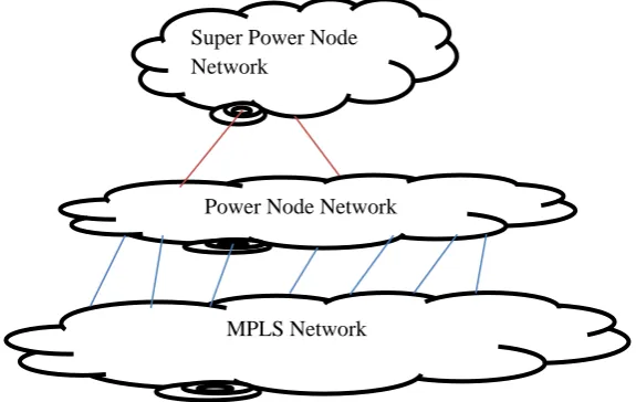
Now suppose condition arises, in which MPLS network becomes too large than in such a case more than one power node(s) are used to implement the concept. Due to this a network of power nodes gets formed which lies on top of MPLS subnet (figure 5 represent’s the concept in depth).
Now until, only one layer of power nodes is present on top of MPLS subnet (See Figure 6) till than if we manage the network or more correctly power node network efficiently the virtually modified multi protocol label switching works correctly. But as soon as we implement the concept of super power node and so on then
Data packet path
Destination node F Control
Packet path
Power Node
A
B
C
E
D
F Ingress
Egress Control
Packet
Control Packet path
Data Packet
Data packet path
Data packet path Data packet
path
used on top of power node network to manage power nodes so the network gets formed looks like conical network hence it is named as conical network. See figure 8.
MPLS Network
Figure 7 Represents concept of super power nodes and conical network.
Power Node Network Super Power Node Network
MPLS Network P2
P2
P2
P2
P2 P2
P2
Figure 6 Represents concept of power nodes (Single Layered). In figure circles marked P2 represents power nodes.
MPLS Network
Figure 5 Represents concept of formation of power node network on top of MPLS subnet.
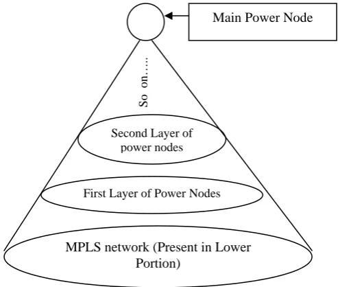
Now if one analyzes figure 8 then he/she could easily figure out that this figure can be generalized in form of cone in which lower portion of cone represents MPLS network. Second higher portion represents first layer of power nodes. Third higher portion represent second layer of power nodes and so on till the apex, where main power node is attached. This concept is shown in figure 9.
3. Conical Network related issues in virtually modified multi protocol label switching
Now we are going to discuss the issues which are main concern of this research journal. These issues are management, delay, communication, network distribution and overall performance. Now we are going to
Figure 9 Represents concept of Conical Network in great detail.
MPLS network (Present in Lower Portion)
First Layer of Power Nodes Second Layer of
power nodes
So on…..
Main Power Node MPLS Network
P2
P2
P2
P2
P2 P2
P2
Figure 8 Represents concept of super power node and formation of conical network. In figure circles marked P2 represents power nodes.
3.1 Management
Management with respect to conical network is art of managing layers of power node(s) and underline MPLS subnet in such a way that aim of very fast data transfer could easily be accomplished. If only one power node is attached to underline MPLS subnet than VMMPLS works effectively. But in real world scenario this is not always true. Since in realty underline MPLS subnet is so wide that more than one power node is needed to do the needful. Now as size of MPLS subnet increases more power nodes have to be imparted in it to make the working smooth. But as number of power nodes gets increased than their management becomes a vital or crucial job.
To handle this management of power nodes we use concept of super power nodes. Hence layer of another node(s) which manages the power nodes are laid down over the first layer of power nodes. These nodes are termed as super power nodes. Using these power nodes one could manage the underline power nodes and underline MPLS subnet easily.
But if these super power nodes itself, become too high in number then a third layer of supervisory power nodes must be laid above super power nodes so the management of super power nodes and nodes beneath it could easily be done. This way a hierarchy of power node(s) layer gets formed. If this hierarchy increases in size than also the management of layers of power node(s) and underline MPLS subnet becomes a hard task to accomplish. Since only control packets moves through power nodes so once the hierarchy increases in size than the depth of movement of control packets must be controlled using some controlling algorithm. Hence the algorithm based complexity of conical network also increases greatly.
As we all know that as network size increases than the chances of failure also increases. So we could say that network size and failure rates are directly proportional with each other. So if the conical network size gets increased with respect to power node(s) layer(s) than the underline MPLS network becomes very wide and subjects to frequent failure and hence the management of failure prone network becomes quite difficult. This much discussion is quite enough for the management issue.
3.2 Delay
Delay with respect to conical network and virtually modified multi protocol label switching is basically the amount of time required to move control packets or data packets from source node to destination (if destination node is present within MPLS subnet) or egress router (if destination node is present outside MPLS subnet). Now here question arises that theoretically power nodes are formed in such a way that no delay takes place at power node. But in reality when size of network increases and control packets has to transfer or move among several power nodes than delay is induced in the movement of control packets from one power node to another (this is because now for transfer of packet from one power node to another very big routing table has to be scanned due to which time is wasted in reading power node’s routing table in search of destination node or node where packet is to be routed next). Weather power nodes are present in the same layer or in the different layer (layer means level of conical network). Due to this realistic condition the chances of life time of control packet expiration also increases. Due to which the communication and data transfer task gets hampered, hence resulting in performance degradation of the virtually modified MPLS protocol.
It is to be noted that if network is small than no delay theoretically occurs at power nodes, hence communication is extremely fast. But when network size gets increased and delay factor gets induced with power nodes than communication becomes slow. Moreover the algorithms for TTL (Time To Live) must be smartly implemented in the conical network in order to cope up with induced delay factor of power node(s).
Not only this but algorithms handling synchronization and acknowledgement mechanisms must be redesigned to cope up with delay factors which gets induced in power node(s) due to bulky sized conical network formation.
3.3 Communication
Communication with respect to conical network and virtually modified multi protocol label switching is process by which two nodes present in conical network communicate with each other. When conical network size increases than the communication between two nodes becomes quite difficult. This happens because now big routing tables have to be searched in order to switch or route the packets from one node to another hence delay factors gets induced in communication process.
Not only this, but we have to take care that packets are switched using best forward equivalence classes. Because it we don’t do this than the communication time gets increased and hence the speed to data transfer gets hampered.
By this much discussion it is to be noted that several smart algorithms which are dynamic in nature must be implemented in conical network. Using which best forward equivalence class could easily be chosen and packet is switched from one node to another in best way with respect to the current position or situation of the conical network.
By increase in conical network size the communication between power nodes also gets a bit hard and due to this communicational delay gets induced in process of communication between two nodes. Moreover several good algorithms must be imparted in conical network by which control packet’s communication could easily and smartly be managed by power nodes.
If we take into account the concept of failure of either links or nodes than the condition of communication becomes more troublesome with increase in size of conical network. This is because rate of failure and size of network are directly proportional with each other. That is if network size increases (either with respect to levels of conical network or nodes present in conical networks MPLS subnet and one layer of power node(s) above it) than failure rate also increases and if network size decreases than failure rates also decreases.
3.4 Network Distribution
Network distribution with respect to conical network and virtually modified multi protocol label switching is the process of distributing underline MPLS subnet in such a way that each portion of the subnet is clearly governed by the allocated power node(s) and these power node(s) cooperates and coordinates with each other in order to make the communication extremely fast and smooth.
Network distribution also contains in it the issues of imparting distributed system protocols to the power node(s) of the formed conical network. So these nodes namely power nodes could easily and effectively execute the VMMPLS on the underline MPLS network.
As we know that distributed system protocols works on loosely coupled processors. So here the distribution of network must be done in such a way that these protocols could easily execute their procedures using minimum messages and minimum resources.
Basically the distribution of underline MPLS subnet is done by network engineer in such a way that maximum benefit could easily be extracted from the distribution and each distribution uses optimal resources in order to accomplish the task of data transfer.
If we distributes our underline MPLS subnet in such a way that levels of conical network gets increased beyond two than there arises difficulty of managing the power nodes at different levels and hence the network performance gets degraded.
3.5 Overall Performance
This limit is flexible and greatly depends upon several factors like speed of processors used in nodes, bandwidth, way of network distribution, algorithms used in network fabrication, etc.
We could easily conclude that the overall performance is dependant on several factors namely bandwidth, management, delay, network division, levels of conical network, algorithms used, processor used in nodes, type of links used for communication, etc.
4. Conclusion
In conclusion we have to only say that the overall performance of virtually modified multi protocol label switching greatly depends upon the formation of conical network and issues related to conical network namely management, delay, communication, network distribution and overall performance. Moreover we could also conclude that the performance of protocol depends upon the size and level of conical network. If size and level of conical network increases then its performance decreases and vice versa. So while implementing VMMPLS in MPLS subnet in which conical network formation is taking place these issues must correctly be handled and taken into account.
References:
[1] Siddharth Srivastava and Umesh Chandra Jaiswal; (November 2011) Virtually Modified Multi Protocol Label Switching, International Journal of Engineering Research & Indu. Appls. (IJERIA). ISSN 0974-1518, Vol.4, No. IV (November 2011), pp. 165-192
[2] Siddharth Srivastava and Umesh Chandra Jaiswal; (July 2011) Study of State Load Dispatch Center and EDI based Software Tree List, International Journal of Engineering Science and Technology (IJEST), ISSN : 0975-5462, Vol. 3 No. 7 July 2011, pages 5818-5824 [3] Anchao Cheng, Xin Yao and Linguo Duan, “Design and Implementation of Integrated Services Switch Simulation Model Based on
ATM-MPLS”, vol. 2, pp. 223-226, 2008
[4] Alouneh, Sahel En-Nouaary, Abdeslam Agarwal, Anjali, “Securing MPLS network with multi path routing”, IT, 2007. ITNG ’07, pp. 809-814, April 2007.
[5] Chen, T.M. Oh and T.H., “Reliable Services in MPLS”, Communication Magazine, IEEE, vol. 37 on 12, pp. 58-62, Dec. 1999 [6] Acharya, A. Ganu, S. Misra, A., “DCMA A Label Switching MAC for Efficient packet Forwarding in Multihop Wireless Network”,
Selected Areas in Communications, IEEE Journal, vol. 24 on 11, pp. 1995-2004, Nov. 2006
[7] Na Lin, Li-xue Song, Tao Yang, “An Improved Mobile Node Fast Handover Algorithm”, Computational Intelligence and Software Engg. 2009, pp. 1-4, Dec. 2009.
[8] Jamali A., Naja N., El Ouadghiri, Benaini R., “Improving QoS in MPLS module”, MMS, 2009 Mediterrannean, pp. 1-4, 2009. [9] Romdhani L., Bonnet C., “Cross Layer QoS Routing Framework for Wireless Mess Networks”, Wireless and Mobile
Communications, 2008. ICWMC 08, pp. 382-388, 2008.
[10] Zhangwei He and Yong Jiang, “Improve reliability of scalable VPN routing via Relaying”, Network Infrastructure and Digital Content, 2010 2nd IEEE, pp. 1061-1066, Sep. 2010.
[11] Van den Berghe, De Turck F. and Demeester P., “SONAR: a plateform for flexible DiffServ / MPLS traffic engg.”, Performance, Computing and Communication, 2004 IEEE., pp. 195-201, 2004.
[12] Polycarpou M., “Intelligent monitoring and fault tolerance in large scale distributed systems”, control and fault tolerant systems (SysTol 2010 conferance). Pp. 480 onwards, October 2010.
[13] Al-Jaroodi J., Mohamed N., Hong Jiang, “Distributed System middleware architecture from a software engg. perspective”, Information reuse and integration-2003 IEEE. pp. 572-579, October 2003.
[14] Tally G., Whitmore B., Sames D., Matt B., Niebuhr B., Bakken D.,“Intrusion tolerant distributed object system: project summary”, DARPA Information survivability Conference and Exposition 2003. Vol. 2, pp. 149-151, 2003
[15] Herbert Schildt, “The Complete Reference Java”, Seventh Edition-2007, Tata McGraw-Hill Edition.