FABRIC FAULT DETECTION USING
IMAGE PROCESSING WITH ATMEL
MICROCONTROLLER
R.THILEPA Department of EEE
Adhiyamaan Educational & Research Institute, Hosur-Tamil nadu 635 109
M.THANIKACHALAM Department of Civil Engineering, Velammal Engineering College, Chennai-600 066 ABSTRACT:
In this paper it is explained how a faulty fabric image is processed through a microcontroller. If there is any fault how it is identified through this ATMEL microcontroller by the circuit operation. For programming the controller Atmel program is used. In addition to that a stepper motor is connected in the output. This motor operates if there is no fault and fails if the fault is identified. This can be implemented in states like Tamilnadu so that the textile field’s income may be increased in an enormous way which in turn raises the country’s income [7].
Keywords: Faulty image; neural network; Atmel microcontroller; power supply; LCD display. 1. INTRODUCTION:
In Textile industries when fabrics are processed it is very tough to identify the faulty section manually since it requires manual visioning continuously which takes lot of time. These drawbacks can be overcome if we use the designed Microcontroller which is described in this paper. This process eliminates the manual faults and minimizes the processing time. Especially in Tamilnadu, Tirupur the Manchester of South India which is also known as the Knitwear capital of India yields major income from these textile fields[6].In the developing countries like India, most defects arising in the production process of atextile material are still detected by human inspection. The work of inspectors is very tediousand time consuming. They have to detect small details that can be located in a wide area that is moving through their visual field [8]. The identification rate is about 70%.
Table 1: Growth Rate of Manufacturing and Textile sector in India:
Year
Growth rate of manufacturing (%) Growth rate of Textiles (%)
2003-04 7.4 -1.1
2004-05 9.1 9.3
2005-06 9.1 8.2
2006-07 12.5 10.9
2007-08 9.0 5.8
2008-09 3.2 -1.2
2009-10(April-November) 7.7 5.8
Table 2: Indian textile and clothing exports to US is lowest in Nov 2009:
Month From world($ bn) From India ( $ mn)
January 6.9 433
February 6 411
March 5.9 450 April 5.8 403
May 6 379 June 6.6 351 July 7.7 378 August 7.5 364
September 7.7 379
October 7.6 355
November 6.2 325
Everyday minimum 2000 square feet fabrics are wasted only for fault where maximum amount of fabric may not faulty. There are different types of faults available in Textile i.e. hole, scratch, stretch, fly, yarn, dirty spot, slub, cracked point, color bleeding etc; if not detected properly these faults can affect the production process massively.
2.METHODOLOGY OF THE PAPER:
Figure 1: Methodology of the Paper
Here the supply is given to the microcontroller first then the fabric image after processing by the feed forward neural network is sent to the microcontroller, if there is no fault in the fabric part then the stepper motor interfaced with the controller will continue its operation[2]. If the fault is identified by the motor then the motor stops the rotation.
Supply to the Microcontroller
Fabric Image sent to the Microcontroller
Microcontroller checks the Image
&sends to driver circuit
Driver circuit to drive stepper
motor
3. MICROCONTROLLER DESCRIPTION:
The below fig gives the pin configuration of ATMEL Microcontroller. The input supply and the output along with interfacing the stepper motor are given below. The output is displayed by the LCD display (i.e. the status of motor).Thereby the fault present in the fabric will be identified.
3.1 PIN CONFIGURATION:
3.2 Pin Descriptions
VCCDigital supply voltage [8]. GND Ground.
Port A (PA7..PA0)
Port A serves as the analog inputs to the A/D Converter. Port A also serves as an 8-bit bi-directional I/O port, if the A/D Converter is not used. Port pins can provide internal pull-up resistors (selected for each bit). The Port A output buffers have symmetrical drive characteristics with both high sink and source capability. When pins PA0 to PA7 are used as inputs and are externally pulled low, they will source current if the internal pull-up resistors are activated. The Port A pins are tri-stated when a reset condition becomes active, even if the clock is not running.
Port B (PB7..PB0)
Port B is an 8-bit bi-directional I/O port with internal pull-up resistors (selected for each bit). The Port B output buffers have symmetrical drive characteristics with both high sink and source capability. As inputs, Port B pins that are externally pulled low will source current if the pull-up resistors are activated. The Port B pins are tri-stated when a reset condition becomes active, even if the clock is not running.
Port C (PC7..PC0)
pins are tri-stated when a reset condition becomes active, even if the clock is not running. If the JTAG interface is enabled, the pull-up resistors on pins PC5(TDI), PC3(TMS) and PC2(TCK) will be activated even if a reset occurs.
Port D (PD7..PD0)
Port D is an 8-bit bi-directional I/O port with internal pull-up resistors (selected for each bit). The Port D output buffers have symmetrical drive characteristics with both high sink and source capability. As inputs, Port D pins that are externally pulled low will source current if the pull-up resistors are activated. The Port D pins are tri-stated when a reset condition becomes active, even if the clock is not running.
RESET
Reset Input. A low level on this pin for longer than the minimum pulse length will generate a reset, even if the clock is not running. Shorter pulses are not guaranteed to generate a reset.
XTAL1
Input to the inverting Oscillator amplifier and input to the internal clock operating circuit. XTAL2
Output from the inverting Oscillator amplifier. AVCC
AVCC is the supply voltage pin for Port A and the A/D Converter. It should be externally connected to VCC, even if the ADC is not used. If the ADC is used, it should be connected to VCC through a low-pass filter.
AREFAREF is the analog reference pin for the A/D Converter 3.2 ATMEL KEY FEATURES:
The ATmega16 provides the following features: 16K bytes of In-System Programmable Flash Program memory with Read-While-Write capabilities, 512 bytes EEPROM, 1Kbyte SRAM, 32 general purpose I/O lines, 32 general purpose working registers, a JTAG interface for Boundary-scan, On-chip Debugging support and programming, three flexible Timer/Counters with compare modes, Internal and External Interrupts, a serial programmable USART, a byte oriented Two-wire Serial Interface, an 8-channel, 10-bit ADC with optional differential input stage with programmable gain (TQFP package only),a programmable Watchdog Timer with Internal Oscillator, an SPI serial port, and six software selectable power saving modes.
The Idle mode stops the CPU while allowing the USART, Two-wire interface, A/D Converter, SRAM, Timer/Counters, SPI port, and interrupt system to continue functioning. The Power-down mode saves the register contents but freezes the Oscillator, disabling all other chip functions until the next External Interrupt or Hardware Reset. In Power-save mode, the Asynchronous Timer continues to run, allowing the user to maintain a timer base while the rest of the device is sleeping. The ADC Noise Reduction mode stops the CPU and all I/O modules except Asynchronous Timer and ADC, to minimize switching noise during ADC conversions. In Standby mode, the crystal/resonator Oscillator is running while the rest of the device is sleeping.
This allows very fast start-up combined with low-power consumption. In Extended Standby mode, both the main Oscillator and the Asynchronous Timer continue to run. The device is manufactured using Atmel’s high density nonvolatile memory technology. The On-chip ISP Flash allows the program memory to be reprogrammed in-system through an SPI serial interface, by a conventional nonvolatile memory programmer, or by an On-chip Boot program running on the AVR core. The boot program can use any interface to download the application program in the Application Flash memory. Software in the Boot Flash section will continue to run while the Application Flash section is updated, providing true Read-While-Write operation. By combining an 8-bit RISC CPU with In-System Self-Programmable Flash on a monolithic chip, the Atmel ATmega16 is a powerful microcontroller that provides a highly-flexible and cost-effective solution to many embedded control applications.
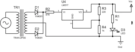
4. POWER SUPPLY FOR THE CIRCUIT:
The power supply to activate the Microcontroller is given below.This gives a constant output of 5v and the Ic used is LM317 and the resistors are acting as potential dividers.The LM117 series of adjustable 3-terminal positive voltage regulators is capable of supplying in excess of 1.5A over a1.2V to 37V output range. They are exceptionally easy to useand require only two external resistors to set the output voltage. Further, both line and load regulation is better thanstandard fixed regulators. Also, the LM117 is packaged in standard transistor packages which are easily mounted and handled. In addition to higher performance than fixed regulators, the LM117 series offers full overload protection available only in IC's. Included on the chip are current limit, thermal overload protection and safe area protection.
All overload protection circuitry remains fully functional even if the adjustment terminalis disconnected. Normally, no capacitors are needed unless the device is situated more than 6 inches from the input filter capacitors in which case an input bypass is needed. An optional output capacitor can be added to improve transient response. The adjustment terminal can be bypassed to achieve very high ripple rejection ratios which are difficult to achieve with standard 3-terminal regulators.
Besides replacing fixed regulators, the LM117 is useful in awide variety of other applications. Since the regulator is “floating” and sees only the input-to-output differential voltage, supplies of several hundred volts can be regulated as long as the maximum input to output differential is not exceeded, i.e., avoid short-circuiting the output. Also, it makes an especially simple adjustable switching regulator, a programmable output regulator, or by connecting afixed resistor between the adjustment pin and output, the LM117 can be used as a precision current regulator. Supplies with electronic shut down can be achieved by clamping the adjustment terminal to ground which programs the output to 1.2V where most loads draw little current. The Diodes are used as rectifiers and the transformer used is step down transformer.Thus the supply is given to the Microcontroller for operation.
Figure 2: power supply circuit
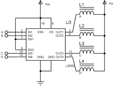
5. L293D DRIVER CIRCUIT FOR DRIVING STEPPER MOTOR:
The L293D is a quadruple high-currenthalf-H driver IC. The L293D is designed to provide bidirectional drive currents of up to 600-mA at voltages from 4.5 V to 36 V[9]. The devices are designed to drive inductive loads suchas relays, solenoids, dc and bipolar stepping motors, as well as other high-current/high-voltage loads in positive-supply applications. All inputs are TTL compatible. Each output is a complete totem-pole drive circuit, with a Darlington transistor sink and a pseudo-Darlington source.
Figure 3: L293D Ic for driving stepper motor
With the proper data inputs, each pair of drivers forms a full-H (or bridge) reversible drive suitable for solenoid or motor applications. On the L293, external high-speed output clamp diodes should be used for inductive transient suppression. A VCC1 terminal, separate from VCC2, is provided for the logic inputs to minimize device power dissipation. The L293 and L293D is characterized for operation from 0°C to 70°C.The Microcontroller is connected through the driver circuit through the pins 24, 25, 23 and 22 by L293D.
6. MAX 232 IC USED TO COMMUNICATE WITH PC:
Figure 4:Max 232 IC to communicate with PC
7. MAIN CIRCUIT OF MICROCONTROLLER OPERATION:
When the supply is given the Microcontroller starts its operation, simultaneously the fabric image is passed to the controller. Here a 5v supply is applied to the stepper motor terminal as an input voltage of Regulator LM317 which gives an output of 5v constantly. After excitation the supply is given to the LCD display as shown in fig below. This LCD display is grounded through pin numbers 3,5,7,8 and 9.The output from the LCD is given to the supply.
Figure 5: complete circuit Diagram
The LED present in the circuit determines the proper voltage supply to the circuit. The power supply is provided to the circuit by the supply circuit given above. This gives a constant output of 5v to the circuit. The Driver circuit is provided to drive the stepper motor at a normal speed. If there is no fault then the fabric part passes through the motor with normal running condition. If the fault is identified by the motor then the rotation stops and detects the nature of fault. The fault may be either color fading, dirt spots, slub, holes, scratches … etc. From this circuit, a positive voltage is supplied to the other motor of our experiment just like the other transformer board and the point is grounded.
MAX 232 is used to communicate with PC.The commands to control the operation of stepper motor by MATLAB programming.
function varargout = FabricGUI(varargin) % FABRICGUI M-file for FabricGUI.fig
% FABRICGUI, by itself, creates a new FABRICGUI or raises the existing % singleton*.
%
% function named CALLBACK in FABRICGUI.M with the given input arguments. %
% FABRICGUI('Property','Value',...) creates a new FABRICGUI or raises the % existing singleton*. Starting from the left, property value pairs are % applied to the GUI before FabricGUI_OpeningFcn gets called. An % unrecognized property name or invalid value makes property application % stop. All inputs are passed to FabricGUI_OpeningFcn via varargin. %
% *See GUI Options on GUIDE's Tools menu. Choose "GUI allows only one % instance to run (singleton)".
%
% See also: GUIDE, GUIDATA, GUIHANDLES
% Edit the above text to modify the response to help FabricGUI
% Last Modified by GUIDE v2.5 21-Aug-2010 17:11:49
% Begin initialization code – gui_Singleton = 1;
gui_State = struct('gui_Name', mfilename, ... 'gui_Singleton', gui_Singleton, ...
'gui_OpeningFcn', @FabricGUI_OpeningFcn, ... 'gui_OutputFcn', @FabricGUI_OutputFcn, ... 'gui_LayoutFcn', [] , ...
'gui_Callback', []); if nargin && ischar(varargin{1})
gui_State.gui_Callback = str2func(varargin{1}); end
if nargout
[varargout{1:nargout}] = gui_mainfcn(gui_State, varargin{:}); else
gui_mainfcn(gui_State, varargin{:}); end
% End initialization code
% --- Executes just before FabricGUI is made visible.
function FabricGUI_OpeningFcn(hObject, eventdata, handles, varargin) % This function has no output args, see OutputFcn.
% hObject handle to figure
% eventdata reserved - to be defined in a future version of MATLAB % handles structure with handles and user data (see GUIDATA) % varargin command line arguments to FabricGUI (see VARARGIN) % Choose default command line output for FabricGUI
handles.output = hObject; inputimage= ones(256,256); axes(handles.axes1); imshow(inputimage); axes(handles.axes2); imshow(inputimage); axes(handles.axes3); imshow(inputimage); axes(handles.axes5); imshow(inputimage);
% Update handles structure guidata(hObject, handles);
% UIWAIT makes FabricGUI wait for user response (see UIRESUME) % uiwait(handles.figure1);
% --- Outputs from this function are returned to the command line. function varargout = FabricGUI_OutputFcn(hObject, eventdata, handles) % varargout cell array for returning output args (see VARARGOUT); % hObject handle to figure
% eventdata reserved - to be defined in a future version of MATLAB % handles structure with handles and user data (see GUIDATA)
% Get default command line output from handles structure varargout{1} = handles.output;
% --- Executes on button press in Defected_Image.
function Defected_Image_Callback(hObject, eventdata, handles) % hObject handle to Defected_Image (see GCBO)
% eventdata reserved - to be defined in a future version of MATLAB % handles structure with handles and user data (see GUIDATA)
[filename, pathname] = uigetfile('*.bmp;*.jpg;*.pgm;*.png', 'Pick an image'); %%uigetfile is a fuction to get images from
%%%from database
if isequal(filename,0) || isequal(pathname,0)
warndlg('Image is not selected'); %%%to show warning dialog use warndlg
else
a=imread(filename); %%%read an input image
inputimage = imresize(a,[256 256]); %%resize that image in to 256 rows and 256 columns
axes(handles.axes1); %%% axes which is shown in GUI file ,,in that showing image imshow(inputimage); %%%imshow function to show image
end
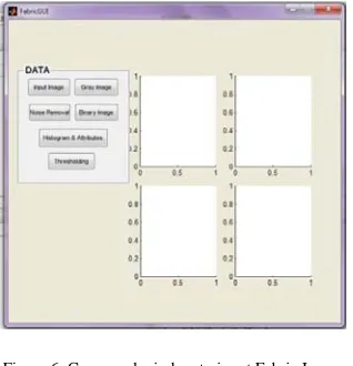
Figure 6: Command window to input Fabric Image
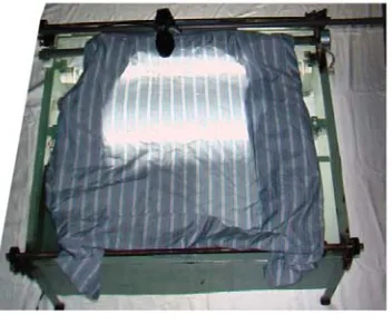
Figure 7:The Real System
The real mechanism and the detection process of the faulty part are shown in the above figure. 8. RESULT AND DISCUSSIONS:
The detection of fault in the system is done by thresholding through the neural network. The mat lab programming is used to run the stepper motor along with the controller. The faults may be either hole, scratch, fade…etc.present on the fabric images are identified. The overall accuracy to detect the fault by this system is given as 80%.Thus by using this system the faults on fabricscan be detected automatically.
9. CONCLUSION:
In most of the textile factories of Tirupur, the defects of the fabrics are detected manually. The manual textile quality control usually goes over the human eye inspection. Notoriously, human visual inspection is tedious, tiring and fatiguing task, involving observation, attention and experience to detect correctly the fault occurrence. The accuracy of human visual inspection declines with dull jobs and endless routines. Sometimes slow, expensive and erratic inspection is the result. Therefore, the automatic visual inspection protects both: the man and the quality. Here, it has been demonstrated that Textile Defect Recognition System is capable of detecting fabrics defects with more accuracy and efficiency. In the research arena, thus our system deletes the manual defects in textile field maximum
.
REFERENCES:
[1] Ahmed Ridwanul Islam, Farjana Zebin Eishita, Jesmine Ara Bubly, “Implementation of a Real Time [2] Automated Fabric Defect Detection System” 2007.
[3] Gonzalez.R.C, Woods.R.E, Eddins.S.L, “Digital Image Processing usingMATLAB”, [4] ISBN 81-297-0515-X, 2005, pp. 76-104,142-166,404.
[5] Newman.T.S and Jain.A.K, “A Survey of Automated Visual Inspection,” Computer Vision and Image [6] Understanding, vol. 61, 1995, pp.231–262.
[7] Ralló.M, Millán.M.S, Escofet.J, “Wavelet based techniques for textile inspection”, Opt.Eng. 26(2), [8] 838-844 (2003).
[9] Textile Views - Textile news, Apparel news, fabric, yarns, Tirupur exporters, Tirupur Readymade garments, [10] apparel news, Tirupur yarn market, and CMT cost.mht
[11] http://www.scribd.com/doc/7015798/Tirupur-case-study [12] http:// en.wikipedia.org/wiki/Tirupur.
[13] http://www.datasheetcatalog.com/atmel/1/.