Cloud-based IoT Analytics for the Smart Grid: Experiences
from a 3-year Pilot
T. Hasan, P. Kikiras, A.
Leonardi
AGT International Hilpertstraße 35 64295 Darmstadt, Germany
{thasan, pkikiras,
ale-onardi}@agtinternational.com
H. Ziekow
∗Furtwangen University Robert-Gerwig-Platz 1 78120 Furtwangen, Germany
[email protected]
J. Daubert
TU Darmstadt / CASED Mornewegstr. 32 64293 Darmstadt, Germany
[email protected]
ABSTRACT
The transformation of electrical grids into smart-grid is seen as one of the major technological challenges of our times and at the same time as one of the key domains for Internet of Things (IoT). Smart-home technologies and corresponding analytics are an integral part of many use cases in this field. In this paper we present a cloud-based test bed for capturing and analyzing smart-home data and report on experiences from a 3 year pilot with a cloud-based system. We discuss on real-world challenges that we encountered throughout the pilot e.g. related to big data volumes and data quality -and describe corresponding technical solutions.
Categories and Subject Descriptors
H.4 [Information Systems Applications]: Miscellaneous
General Terms
Internet of ThingsKeywords
Smart-home, IoT, Analytics
1.
INTRODUCTION
In recent years, environmental and economic considerations have fueled investments in renewable energy sources. For instance, member states of the European Union have set the so-called 20-20-20 goals, to obtain at least 20 percent of their electricity from renewable sources by 2020. Germany even strives for 80 percent renewable sources in the energy mix by 2050. However, this change in the energy supply has severe implications on the operation of electrical grids and the corresponding ICT infrastructure. Decentralized
∗
Main part of the work was done while at AGT Interna-tional.
production (e.g. with solar panels on roof tops) causes the need to expand grid management infrastructures to the low voltage level, i.e. the level of streets and houses. However, it remains an open question how technical solutions for grid management of on this local level should be designed.
Smart-home technology is seen as a key enable for better understanding and managing the energy consumption on in the low voltage grid. To better understand the correspond-ing challenges and solutions for data capturcorrespond-ing and process-ing, the German federal government has provided funding for the PeerEnergyCloud research project [12]. This paper reports on a cloud-based test bed for capturing and analyz-ing sensor data from smart-homes that was developed and piloted throughout this project. The pilot was conducted using smart-home hardware packages with sensors for cap-turing device specific energy consumption as well as sensors for environmental conditions (e.g. room temperature). In total we used 60 packages that were installed in various se-tups and different homes. Overall, we observed installations for up to three years and captured about 12 Billion sensor measurements in total. The emphasis of this paper is on the technical solutions that we developed for capturing and an-alyzing the data as well as on the challenges that we faced in the real-world deployment. Key contributions of the paper are the following:
• We provide a solution architecture and details on tech-nical components for a test bed that supports cloud-based service on top of smart-home sensors.
• We discuss the real-world challenges for data capturing and analysis that we derived from a 3 year deployment in the smart home/smart grid domain.
• We present technical solutions that respond to the challenges that we encountered throughout the pilot.
The remainder of the paper is structured as follows. Section 2 discusses relevant related work. Section 3 provides a high level overview of the solution architecture and different com-ponents of our test bed and Section 4 discusses operational issues that we faced when piloting the system. The subse-quent sections address technical details of the key compo-nents in our test bed and the mechanisms for addressing the
TRIDENTCOM 2015, June 24-25, Vancouver, Canada Copyright © 2015 ICST
encountered challenges. Section 5 drills down into the imple-mentation of the gateway component that facilitates sens-ing within homes. Section 6 describes specific monitorsens-ing components that we developed for the smart-home domain. Section 7 presents analytics components that we developed for supporting smart-grid applications and discusses how we addressed the corresponding big data challenges. Section 8 presents end-user services on top of our test bed along with a privacy policy engine that we developed. Finally, we con-clude the paper and discuss future work in Section 9.
2.
RELATED WORK
Several systems integrating sensor networks with energy man-agement systems at the consumer premises have been pro-posed so far.
The closest to ours project is Linear [9], a Flemish Smart Grid project focusing on solutions to match residential elec-tricity consumption with available wind and solar energy, an approach referred to as demand response. Linear se-lected and deployed 2 types of smart appliances. The first type consists of postponable appliances, such as dishwash-ers, washing machines and tumble drydishwash-ers, 445 of which were deployed in the Linear pilot initiative. The second type con-sists of buffered appliances, of which Linear included 15 do-mestic hot water buffers and 7 electrical vehicles. In the field test, 110 houses were equipped with smart meters. In each Linear household a home gateway communicated with the measurement devices and smart appliances and sent all collected data in real-time to the backend of the gateway provider. The data was then forwarded to the Linear pilot backend. The project suffered from the amount of data and transactions collected since no big data technologies to han-dle that were used. Additionally, in-house communications were one of the major sources of technical malfunctions. Lin-ear, installed on average 11 ZigBee plugs in each home, half of them serving exclusively to bridge communication signals. Linear preferred “Ethernet over PLC to Wi-Fi” for connect-ing the different modules in the house with the gateway. This choice quite often caused conflicts with existing appli-cations such as the home network and digital television. As a result, Linear technicians repeatedly needed to reconfig-ure and test the complete in-house communication setup. According to the Linear support team “Some families were so excited about the possibilities of the Home Energy Man-agement System that they started moving plugs to different locations in order to trace standby losses, not being aware that they were messing up the network to the extent that the fridge plug started showing the behavior of a television in our databases”. Similar issues have been experienced also in our pilot and in one of the following sections we will present our mitigation approach.
In [5] the authors evaluate the performance of an in-home en-ergy management system based on a ZigBee wireless sensor network. The focus there is the performance of the system on the application level, meaning the investigation of the potential of both energy management and demand manage-ment. The evaluation that has been performed by the au-thors is based on simulation results, and not on real network deployments in households as in our work.
Similarly, in [14] energy management in homes has been
Figure 1: High-level architectural overview of the PEC ecosystem
investigated on a pilot consisting of only 3 households in Sacramento. The solution has been implemented using off-the-shelf components based on power line communication, and it included a web-based monitoring and control of home appliances.
3.
OVERVIEW OF SYSTEM
ARCHITECTURE
In this section we provide an overview of the main compo-nents of our testbed and the design decisions that drove the architecture. Key components are further detailed in sec-tions 5, 6 and 7. We developed the testbed to support pilot-ing of smart buildpilot-ing technologies for deliverpilot-ing value-added services to end-users as well as for supporting grid opera-tions through advanced analytics. Thus, the architectural design was driven by the need to (a) integrate sensors de-ployed in private homes, (b) deliver cloud-based services to end-users, and (c) support big data analytics over captured sensor data. Figure 1 gives an overview of the system ar-chitecture that supports these needs. In the arar-chitecture we distinguish two main physical layers: the local layer (hosted within private homes) and the backend layer (hosted in an cloud environment).
3.1
Local Layer
The main design goal of the local layer is to provide an easy to use solution for installing and connecting sensors in pri-vate homes to the backend infrastructure. Easy setup is a key requirement because persons with little technical expe-rience should be able to make installations in their homes.
Our solution for the local layer comprises wireless sensors and a gateway component that we deploy in private homes. The sensors are smart building sensors that capture elec-tricity consumption of individual devices and some context information within the home (e.g. room temperature and brightness). In addition, some sensors act as actuators that can control attached devices (i.e. switch power on or off). Several vendors offer sensors for smart buildings, using a range of different protocols (e.g. [1, 2]).
sen-sor types and communication protocols. For the pilot we choose ZigBee based sensors as a solution that enables wire-less deployment and coverage of larger houses through multi-hop communication.
When deployed in a house, the sensors establish a house specific network (i.e. with user specific network ID and en-cryption) and connect to the gateway component. The main task of the gateway is to bridge between the smart building sensors and the backend. It captures the arriving sensors data, buffers them, and forwards them via REST calls to a receiving component in the backend. In addition, the gate-way provides a REST interfaces, allowing the backend to issue ad-hoc queries for sensor data, meta data, and to issue actuation commands.
The gateway software is based on Java and OSGi, mak-ing it compatible with a wide range of hardware platforms. Within the pilot we used media PCs to run the gateway but more lean hardware platforms are viable alternatives. Zig-Bee communication is enabled via a USB dongle and com-munication to the backend is established via the Internet. The network parameters for the ZigBee communication and for connecting to the backend are preconfigured when the components are shipped to the users. Through this pre-configuration, the installation on site is limited to deploy-ing the sensors and connectdeploy-ing the gateway to an Internet router, thus is executable without detailed technical knowl-edge. All communication to the backed in encrypted via a VPN that the gateway connects to during startup. Besides encryption, this setup has the benefit of enabling secured communication from the backend to the gateway past fire-walls and routers.
3.2
Backend Layer
The backend is hosted in a private cloud infrastructure. The main purposes of the backend are (1) collection of sensor data, (2) provisioning of web-based value added services to end-users, (3) provisioning of analytics for grid operations. Figure 1 shows the high level components that we roughly group into three sets. We refer to one set as Management Components that support the management of software and hardware deployments in the testbed. We refer to a second set of components as End-User Applications. These compo-nents provide end-user facing services and connectivity. A third set of components is called Analytics Components that provides storage and processing capabilities for big data an-alytics. The Management, End-User Applications, and An-alytics Components, have different non-functional require-ments, leading to different technology choices for their im-plementation.
The Management Components are used to manage and mon-itor the infrastructure. This includes health monmon-itoring of all system components as well as management of user ac-counts and metadata about the deployments. In general, monitoring of the system health and management of user ac-counts is only moderately complex and can be implemented with standard approaches. However, the management of deployment metadata in an IoT context poses significant challenges and calls for special techniques. Metadata in-clude information such as the association of a sensor to the object that it senses (e.g. an energy sensor attached to a
fridge). In an uncontrolled environment - such as private homes - deployments might change without an explicit noti-fication to the system (e.g. users redeploy smart plugs with-out updating the meta data). We address this challenge with dedicated analytics which implement a concept that we call “self-conscious sensor”. Details about this concept and our solution are given in Section 6.
The End-User Applications provide users with statistics of their energy consumption and means to control (switch) their devices via web interfaces. Key requirements for these components are related to a good user experience in terms of system responsiveness. The challenge is to timely process the high resolution data from the sensors and to provide the results via an interactive interface. We address this chal-lenge by leveraging concepts from the lambda architecture [10]. That is, we build the end-user applications on top of a database that acts as a serving-layer and feed the database via a dedicated batch-layer and speed-layer. The batch- and speed layer preprocess and aggregate the data for presenta-tion. The serving layer only holds the subset of the complete sensors data which are needed for the end-user application as well as pre-computed aggregated statistics. This reduc-tion of the dataset and pre-aggregareduc-tion keeps the serving layer reasonably small and supports fast response times for end-user applications that query the data.
The requirements for the Analytics Components are mainly driven by (a) the large data volumes and (b) the support for exploratory data analysis. For every household in the pilot we receive about 1.2 million sensor measurement per day. This calls for storage and processing technologies that can handle big data. The batch layer provides a scalable stor-age that holds all raw sensor data and holds components for distributed batch processing (e.g. including a MapRe-duce framework). The speed layer leverages technologies of complex event processing that keep the recent incom-ing data in memory and run analytics over the live data streams. This design enables us to handle large data vol-umes in our analytics. It also addresses the need for flexi-ble explorative data analytics by keeping the complete raw dataset and thus supporting the addition of arbitrary new analytics functions. More details about the implementation of the Analytics Components in Section 7.
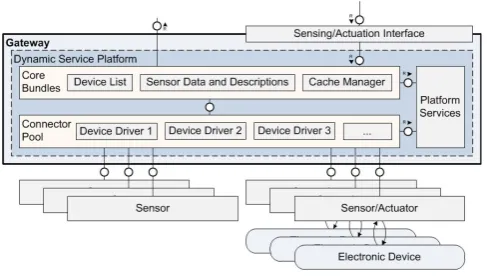
inter-Figure 2: Gateway components.
net connections and downtimes of the backend. While loss of live data cannot be avoided, we implemented a solution to fill in resulting data gaps in the master data set of the backend. This is, we persisted recorded data on the local gateways and updated the backend as soon as the Internet connection was re-established (see Section 5 for details).
The challenge of sensing uncontrolled environment is inhered to the application domain of smart homes. The tested had to cope with a range of distortions caused by users. Examples of such distortions include accidental disconnection of the gateway (e.g. during cleaning) and rearranging of sensors. Such distortions are inherent and cannot be prevented by the system. Hence, the system must be able to adapt. We addressed this by extended monitoring capabilities and an-alytics which enabled the system to be aware of unintended changes in the deployment. Section 6 provides more details about the specific monitoring solutions.
5.
GATEWAY COMPONENTS
The gateway provides an interface between the sensor net-work and the rest of the system. This means not only bridg-ing the gap between the likely short-range network used by the sensors, but also the device-specific details and the higher-level, device-agnostic middleware in the backend [3].
The proposed gateway provides an abstraction layer which removes the device-specific details of the sensors and of-fers the gathered data in a standardized, device-independent way. The gateway also handles the management of the de-vices which are attached to it. For example, managing the registration of new devices, providing security and fault de-tection. The gateway’s functionality should be extensible during the deployment lifetime of the gateway and the gath-ered data should also be stored in a cache on the gateway for optimization purposes. The gateway design is split into three main components: Core Bundles, Connector Pool and Platform Services.
5.1
Core Bundles
The Core Bundles perform the majority of tasks carried out by the Gateway. The set of Core Bundles comprises of the following components:
• The Device List, which handles joins and leaves of the devices to and from the sensor network so that the registration and subsequent de-registration of devices can be pushed to the backend.
• Sensor Data and Descriptions: the attached sensors need to be described in a device-independent way so that the backend can utilize the data and descriptions without the need of having explicit knowledge of the underlying implementation details of the various sen-sors.
• Cache Manager: to defend against failures of network connectivity, the gateway needs to cache sensor data temporarily until connectivity has been restored. The data needs to be kept in a cache for a pre-determined amount of time before being removed.
5.2
Connector Pool
The Connector Pool is where the device-specific protocol adaptors reside. The Connector Pool should have a num-ber of device-specific protocol adaptors so that a numnum-ber of different devices using different networking technologies can be attached to the gateway in a modular fashion. Each protocol adaptor should completely encapsulate the device-specific details of the sensor, leaving the rest of the gateway to operate in as a generic way as possible. The protocol adaptor will handle the actual interface to the sensor net-work in order to receive data and all associated additional device-specific functionalities such as sending commands to the sensors for both actuation (where available) and man-agement purposes.
5.3
Platform Services
Platform Services are generic house-keeping services to man-age the Gateway as a service platform. In order for the gate-way to be upgraded during its deployment lifecycle, it must be implemented in a modular way. These modules must be “hot pluggable”, meaning that they can be dynamically up-graded without having to stop the running system. In order to achieve that, a set of Platform Services must be present providing an appropriate system and service platform which enables such hot plugging of software components.
5.4
Gateway Implementation
In order to meet the requirements described in the previous Section and satisfy the modularity and extensibility needs, we chose to build the gateway using the OSGi service frame-work. OSGi provides a platform where Java modules (called bundles in OSGi) can be dynamically installed, stopped, started, updated and uninstalled. By offering a service-oriented architecture, bundles can register themselves as vices, discover existing services and bind to listening ser-vices. These factors together mean that the functionality of the gateway can be modified during its deployment life-cycle thereby meeting our requirements. We created the following services in Java on top of OSGi:
TheXBee protocol driverimplements the XBee specific driver and performs the following functions:
• Data handling: data is received from the attached de-vices and the payload is parsed and sent to the Cache Manager and also to the Data Push Interface so that the data can be forwarded to the backend for further processing.
• Actuation: if an application wishes to switch a device on or off then the XBee protocol driver creates the appropriate message to be sent to the device so that it can be activated or deactivated.
The Device List provides a dynamically updated list of attached devices which can be queried by the backend and thereby also provided to the applications. The Device List contains meta-data about each sensor that is attached, for example, its MAC address, type and if it is a power plug, whether or not its relay is switched on or off.
TheSensor Data and Descriptionsare a set of high-level descriptions of the sensors themselves and the data they collect. The sensor descriptions are used by the gateway to keep track of which sensors are attached to the gateway at any particular time as we typically have sensors of multiple types in a deployment. The sensor data descriptions are used to convert the data sent by the sensors into a format which can be used by the backend and thereby the rest of the system.
When a message arrives from a sensor, it is processed by the gateway and the relevant data is extracted. A single sensor device can send messages with different types of data as it may have multiple sensors on-board (e.g., temperature, light, humidity, etc.) so the gateway needs to be aware of the different types of data that can be expected from the sensors.
Sensor Data 1Unformatted sensor data
BRI=391lx TEM=26.8C BAT=OK UBAT=4.72V
The Sensor Data 1 shows an example of the unformatted sensor data as it arrives from the sensor at the gateway. The gateway parses this data and creates a internal representa-tion of this data using the sensor data itself, informarepresenta-tion from the packet header and the time and date when the packet has been received.
Sensor Data 2Formatted sensor data in JSON format
"{\"MACADDR\": \"00:13:A2:00:40:61:B5:E4\",\"TYPE\": \"ZBS-121\",\"DATE\": \"2012-05-11 15:12:06\", \"VALUES\": {\"TEM\":27.2,\"BRI\":404,\"BAT\ ":\"OK\",\"UBAT\":0.0, }}"
This internal representation is then converted into a JavaScript Object Notation (JSON) stanza which is then sent to the backend for processing. An example of the JSON stanza is shown in the Sensor Data 2.
TheCache Managerinteracts with a local database (e.g., PostgreSQL) to temporarily store the gathered sensor data.
The Database is also accessible via the Sensing/Actuation Interface so that the applications can access the cache if necessary.
TheRepresentational State Transfer (REST) Inter-face is the implementation of the interfaces used by the gateway to interact with the backend. It provides the fol-lowing features: get the latest data from the database for a specific device, turn the relay of a device on or off (actua-tion capabilities) and send gathered data from a sensor to the Backend. The REST Interface is implemented using the JAX-RS framework and formats the payload of the REST calls in a JSON format.
6.
MONITORING AND SUPPORT
SERVICE
In this Section we describe two important components re-lated to the management of the system, the monitoring and the plug change detection, respectively. These two compo-nents make the system itself “self-conscious” about its status and possible misconfiguration caused by the users.
6.1
System state monitoring
As we have to deal with a complex distributed system with many potential error sources, the state of the system has to be monitored constantly to be able to quickly detect faulty or abnormal behavior. For that, a number of services were implemented to help the administrators keep an overview. As the deployment consists of gateways connected through a VPN to a set of backend servers, it is obvious that it is crucial to monitor each part to a certain extent. Therefore, these three points for monitoring have been identified and covered in our deployment.
As implemented in our deployment, an alert can be raised when the number of connected sensors to a specific gateway drops, hinting at an unstable local ZigBee network or other problems with the gateway software.
As the VPN connection is an important part in the com-munication infrastructure, it has to be monitored as well. Services that dispatch alerts when new gateways connect or disconnect are needed. Therefore, in our case, gateways send an email whenever they connect to the VPN to be aware of newly set up installations or unexpected restarts of gate-ways. For manual inspection, there is a script that lists all connected gateways.
Furthermore, the responsiveness and availability of the back-end servers themselves are crucial. To monitor the servers, we implemented services that look for recent activity in the databases. If the data is not written through to the database immediately, it can hint at problems with the REST-Interface or problems with handling the high amount of incoming REST calls and the resulting database writings. Because of pilot project character, it was of advantage to periodically restart the VMs to eliminate all stray or “buggy” processes that might have been initiated by faulty automatic calls of the REST interface or other components.
manually or on a daily basis by e.g. a cron job. It came to our attention that sending automatically generated status emails through local SMTP server instances to a number of interested administrators is very useful for keeping a general overview of the system.
6.2
Plug change detection
Due to the loose installation of sensors and the fact that private homes are very dynamic environments, we could ob-serve that users tend to switch sensors or connect new de-vices to their system without providing the information to the system. Any analytical component working with data from a household where the configuration has changed will yield wrong results. Therefore, we designed a component that can take required countermeasures to ensure the con-sistency of the data.
We implemented a scalable framework (based on Apache Storm and the machine learning framework Weka) that can prompt the user to confirm a detected configuration change or automatically trigger recalculation of any analytics mod-els [8]. For this, it aggregates the consumption measure-ments for each device of a specific household over 24 hours and extracts a set of features from this aggregated data. With feature vectors from multiple days and from all devices of a specific household, two kinds of machine learning models are learned. The first is a classifier that accurately classifies feature vectors extracted from newly incoming data as one of the devices the model has been learned with. By having such a mechanism working with a high accuracy, (cyclic) swaps can be/are detected easily. However, for the case that we want to detect previously unknown devices, this approach gives only limited possibilities to asses the confidence with which newly collected data really comes from a device that is known to the household model, as a classifier will always chose one category, be it fitting or not. Therefore, we rely on a second model that clusters the data into as many clusters as there are sensors in the smart home kit and look at the distance of a newly incoming feature vector to the closest cluster center. If this distance is above a certain threshold, we can accurately assume that the data the feature vector has been extracted from is not coming from a usually at-tached device. For the first component we use statistical features like minimum (non-zero), maximum and average daily consumption among others. In addition to that, a his-togram of the daily consumption data is computed and put into the feature vector as is. For the second component it suffices to only rely on the statistical features.
As stated, the performance of the swapping detection is in-evitably linked with the performance of the classification mechanism. Our system is able to detect the devices with an accuracy of 97.08% and therefore also detect cyclic swaps very accurately.
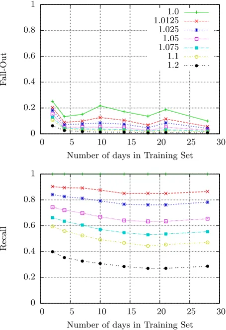
When it comes to evaluation of the second model, we have to look at two parameters of the setup, namely the number of days of training data per device in the training set and the cluster distance threshold that determines the distance to the closest cluster center after which the device shall be detected as unknown.
In order to be able to evaluate this model appropriately, we
0 0.2 0.4 0.6 0.8 1
0 5 10 15 20 25 30
F
a
ll
-O
u
t
Number of days in Training Set 1.0 1.0125 1.025 1.05 1.075 1.1 1.2
0 0.2 0.4 0.6 0.8 1
0 5 10 15 20 25 30
Re
c
al
l
Number of days in Training Set
Figure 3: ClusterDist-based decision over number of days in training set and varying thresholdTclusterDist
furthermore need metrics tailored to the specific problem, providing the possibility of tuning the system towards the intended performance. Therefore, a short description of the chosen metrics shall be given at this point. We identified two questions that are of high interest in our scenario: How many of the unknown devices are we able to detect? And how many false alarms are issued by the system? The metric addressing the first question is theRecall. In this context, the Recall describes how many of the unknown instances in the test set really were recognized as such. The second measure is Fall-out. It describes how many of the tested known devices have been incorrectly classified as unknown devices, leading to a false alarm. It is key to maximize Recall and minimize Fall-out.
As can be seen in Figure 3, increasing the thresholdTclusterDist
in the training set the system requires less time to set itself up to operate but will possibly work less robustly.
When taking a look at the application scenario of prompt-ing the user for confirmation of changes made to the smart home environment, a high fall-out poses a problem. It can be perceived bothering or even disturbing to the user if he gets gets prompted on a too frequent basis. Therefore, we propose to mitigate this issue by setting a minimum num-ber of consecutive days where an instance representing the behavior of an appliance at that day has to be detected as unknown under utilization of the same model. In the second scenario, where the detection of an unknown device triggers recalculation of an ML model, the false alarm rate is not as harmful, as an adequately designed system should be able to cope with a moderate amount of recalculations. In this case, the parameters can be chosen so that we have a high detection probability and an amount of false alarms that causes still manageable overhead.
7.
ANALYTICS COMPONENTS
A central aspect of the pilot was to provide analytics compo-nents for the captured energy data. A particular challenge was to choose the right processing paradigms and technolo-gies to cope with the high amount of sensors data. This section provides insights about the requirements and corre-sponding solution architecture that we used the project. In addition, we discuss the implementation selected analytics components (i.e. consumption prediction and power quality anomaly detection) in detail.
7.1
Requirements and Solution Architecture
The solution architecture for our testbed was primarily driven by three key requirements: (1) handling large data volumes, (2) handling high velocity data, and (3) flexibility regarding functional extensions. The first two requirements directly map to two of the three Vs that define big data (i.e. vol-ume and velocity). The requirement for handling large data volumes is driven by the huge number of capture sensor mea-surements. Throughout the pilot we collected approximately 12 billion data points (about 1.2 million per household and day). This causes the need for technologies that can deal with this amount of data. The requirement for handling high velocity data is due to the need for real-time analy-sis of the incoming sensor streams. Applications that drive the need for real-time analysis are for instance load mon-itoring for end-users and consumption prediction for load balancing. End-users should have access to a live view of their consumption to get direct feedback about how their behavior influences energy usage. Consumption prediction for load balancing benefits from live data to drive short term adaptions of energy loads and support local balancing of the energy grid [16]. This caused the need for processing tech-nologies that can deal with continuous processing over data streams. The third requirement - flexibility regarding func-tional extensions - stems from the nature of the testbed. The aim is to support exploratory data analysis and a growing number of analytics services. Hence, extensibility regarding the analytics functionality is a key concern for the solution architecture.In order to address the above discussed requirements we adapted concepts of the lambda architecture for our
solu-tion [10]. The lambda architecture provides a conceptual framework for the design big data systems. It defines the three layers (1) batch layer, (2) serving layer, and (3) speed layer to deal with different requirements independently and though dedicated technologies.
We use concepts of the batch layer to address the require-ment for handling large data volumes. The batch layer per-sists all data and support parallelized processing in batches. It aims on scalability and high throughput at the cost of short response times. Our testbed persists all sensor data in a master data set that serves at input for distributed batch processing in a computer cluster. It allows exports as plain csv files and thereby supports a batch processing with a range of distributed processing system (e.g. Hadoop). We discuss an embodiment that we used in the pilot in [13].
We use concepts of the speed layer to address the require-ment of handling high velocity data. The speed layer sup-ports continuous processing in real-time but does not persist data. It keeps all data in memory and thereby enables real-time analysis. Input data from the sensors arrive at the system in a push based manner as read events and are ab-stracted though an adapter. This allows to connect to a range of stream processing systems (e.g. Apache Storm). We discuss specific embodiments that we developed in the pilot in [15].
To address flexibility for analytics extensions we follow the data modeling principles defined for the master data set in the lambda architecture. Specifically, we store sensor mea-surements in a fact based model, keep all raw meamea-surements with a timestamp and refrain from updates as well as from aggregation or non-trivial preprocessing. This ensures that the maximum information value of sensor data is kept and future analytics are not constrained by design decision in the storage.
In the following subsections we discuss the implementation of two representative analytics components within the above framework.
7.2
Power Quality Anomaly Detection
Power quality anomaly detection is an analytics components that detect power quality issues in the low voltage grid. Specifically, it provides descriptive statistics about the devi-ation of the measured voltage from the target voltage. This deviation is subject to regulations and can impact the func-tioning of electrical devices or even cause damage. Conse-quently it is of high interest for grid operator to detect and understand voltage deviations within their grid. With our testbed we provide means to analyze this aspect of power quality on a new level of detail, i.e. the level of individual houses and even power outlets.
0 200 400 600 800 1000 1200 1400
2 days
6 days
10 days
14 days
18 days
22 days
26 days
30 days
que
ry
t
ime
(se
cond
s)
analytics scope (covered time)
RDBMS Hadoop (1 Node) Hadoop (3 Nodes) Traditional Database System
Hadoop Based Solution
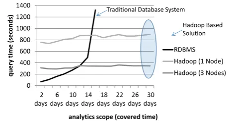
Figure 4: Comparison of query execution times with increas-ing database sizes
approached of the batch layer suitable for the implemen-tation. An initial setup with batch processing on top of PostgreSQL failed to cope with the data volumes (see Fig-ure 4). However, connecting the master data set with a Hadoop cluster and implementing power quality analysis as MapReduce jobs made the analysis feasible and proofed to be scalable (see Figure 4). Here, the map operation ex-tracts the required subset of data points and computes the deviation, while the reduce jobs compute the aggregate de-scriptive statistics. Both operations run in batch mode and can be completed for the describe sample experiment in less than 7 minutes on a 3 node cluster.
7.3
Consumption Prediction
Accurate consumption prediction is a key enabler for load balancing in the local grid. The aim is to actively influ-ence consumption so that local production (e.g. from solar panels) and local consumption match a closely as possible within a neighborhood. In order to influence consumption (e.g. though demand response mechanism) it must be known in advance. At least a few minutes lead time are desirable to invoke demand response measure.
We developed a prediction mechanism that uses the lat-est real-time information and household specific prediction models to make load predictions 15 minutes or an hour ahead. Our solution uses machine learning based prediction models that are trained for individual households and ap-plied this models over live data streams. Experiments have shown, that this approach can improve prediction accuracy in the described setting [16]. However, it poses significant processing challenges. One key challenge is the training of individualized prediction models using the high volume of stored consumption measurements. Another key challenge is the continuous application of the models over real-time data streams.
We addressed this challenge by leveraging technologies of the batch layer and the streaming layer. We use the batch processing to train prediction models based on the collected historical data. This process covers feature extraction from the data records as well as the training process itself. The trained models are then loaded into the speed layer and re-main in memory for real-time application. For real-time ap-plication, the input features are also extracted from the live data stream using in-memory operations. In a test
imple-mentation following this paradigm we achieved continuous predictions with update rates of 0.5 Hz for 1000 households on a single machine (see [15] for details). The specific imple-mentation was done with the CEP engine Esper for feature extraction in the stream [6] and Weka libraries for training machine learning models [7].
8.
END-USER SERVICES
In this section we share experiences in providing web based end-user services on top of smart-home data, and report on challenges that we faced with common technology stacks for such a setup.
8.1
Energy Consumption
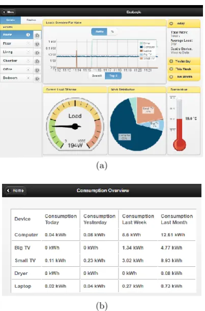
Within our testbed we provided a set of end-user services that allowed users to better understand their energy con-sumption. These services were a major driver for pilot users to participate in the project. The provided services in-clude live statistics of device specific consumption values as well as long term statistics. In additions, the end-user ser-vices include functionality for remote control of actuators (i.e. switching smart plugs). Figure 5 shows screenshots of two sample services. Service 1 (Figure 5a) visualizes sen-sor data in real time and provides device specific as well as room specific consumption statistics. This includes a con-tinuously updates live chart over the past few minutes as well as aggregate statistics that go back to the first mea-surement. In addition, the service allows remote switching of actuators. Service 2 (Figure 5b) provides device specific long term statistics. The statistics go back up to a month and in addition show a drill down of the consumption for the past week, the past day, and the current day. Despite its simplicity the service was very well perceived by end-users and turned out to be a key motivator for participation.
All services are accessible via a web interface. They are im-plemented following a typical design with a standard web-server on top of a relational database PostgreSQL (see Fig-ure 1). The web based services were already launched early in the project when the components for big data processing were not available yet. However, this setup resulted in a set of challenges throughout the project.
A key challenge that we faced was that performance issues quickly arise when providing the described services on top of relational databases. Due to the high number of records (about 1.2 million records per house and day) maintenance operations like e.g. adding indices or exporting data very time consuming. Also, timely delivering query results re-quired to tweak the database.
(a)
(b)
Figure 5: Service 1 with live statistics (a) and Service 2 with long term statistics (b)
needs to go back through millions of records and has a long response time.
Another challenge was the provisioning of long-term statis-tics. In Service 1 we show the device specific consumption since the start of recording. Ad-hoc computation of this statistic from the history of recorded load values is not fea-sible in a timely fashion (i.e. it would require computing the integral over the load curve with hundreds of millions of values). Here, we leverage a feature of the used smart plugs. These plugs provide an accumulated work value for the mea-sured energy since installation. This value is transmitted with every measurement and we could use it directly in the statistics of Service 1. However, we still faced performance challenges for the more fine grained statistics of Service 2. Here we again leveraged the accumulated work value but the resulting queries still took several seconds due to the need for handling data gaps. The delay was too long for a satis-fying user experience. Hence we implemented materialized view of the query results that were regularly updated with batch jobs.
8.2
Privacy
The smart metering ecosystem may facilitate a multitude of applications and value added services (VAS). Security and privacy are a major concern in this context as these appli-cations and services directly affect users’ everyday life and may collect a substantial amount of sensitive data.
Figure 6: Privacy Model.
In order to enable these services new security and privacy solutions are required. The user needs simple-to-use mech-anisms that provide a transparent view on all data that is collected and processed within such an ecosystem. The user should be in perfect control of which data is collected, how it is processed and which data is exchanged with which third parties. The PEC Privacy Dashboard is one of the compo-nents developed for the PEC project designed to define and control access to sensors. Fig. 6, depicts the components and their interaction.
The user interacts with a component called Privacy dash-board to review current access control rules and to modify as well as add rules. The user input from the privacy dash-board is transformed into statements in a given policy lan-guage. In order to make our approach as open as possible XACML [11] is used as the policy decision language, as its expressiveness allows full coverage of all necessary aspects for our application scenarios. These policy statements are then used to evaluate access requests from various appli-cations. Specifically, the Policy Generator translates these PEC specific rules into generic XACML rules, policies, and policy sets and store them in the Policy Store. Service re-quest data or data streams from an interface associated with the Policy Enforcement Point (PEP). The PEP translates data requests into XACML queries and forwards them to the Policy Decision Point (PDP). The PDP will load cor-responding XACML policies from the store and attempt to decide on the request.
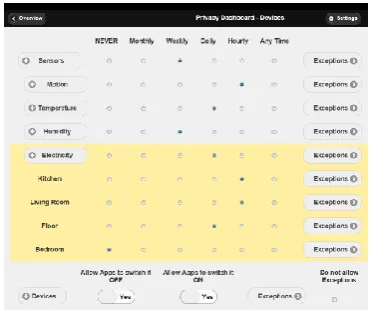
In the current version of the privacy dashboard shown in Fig. 7 deployed sensors and devices are presented to the user in a hierarchical fashion grouped first by the sensor type (e.g., motion, temperature, etc.) and within this group according to actual sensor location. While this layout reflects logi-cal structure according to types of information requested from each application, it can easily be modified or adapted. Future adaptation might include information regarding the requested sampling rate of the service, or the sampling rate required for a particular service level.
Figure 7: Privacy Dashboard.
9.
CONCLUSIONS
In this paper we have provided results that were obtained thought a three year pilot with a cloud-based test bed for capturing and analyzing smart-home data. Our results in-clude findings on real-world challenges in the application domain as well as technical solutions for addressing them. Among the challenges we found issues with data quality and data loss on several layers of cloud-based IoT solutions. In many cases, the issues are inherent to the application domain were we sense in home environments were users intentionally or unintentionally interfere with the operations of the sys-tem. With our solutions for sensor monitoring and deploy-ment change detection we have shown ways how to address this issues. However, we see room for additional research and development efforts to expand the pool of techniques to cope with the data quality challenges. In particular, new techniques may be desirable when expanding the solution to new types of sensors.
Another set of key issues that we faced in the pilot was related to big data challenges. Our findings provide strong indication that classical relational database systems are hard use in given setup and dedicated big data technologies can provide better alternatives. We have shown solutions for a specific set of analytics that we have developed. Further research should expand the scope of considered analytics to validate and possibly adapt our suggested solutions for big data processing.
Overall, our work shows researchers as well as practitioners in the smart grid domain what challenges they have to ex-pect when integration smart home technology. In addition, we describe solutions and approaches that can be followed and expanded to tackle such challenges.
10.
ACKNOWLEDGEMENT
This work has been supported in part by the German Federal Ministry of Economics and Technology, project PeerEnergy-Cloud which is part of the Trusted PeerEnergy-Cloud Program.
11.
REFERENCES
[1] Z. Alliance. Ieee 802.15. 4, zigbee standard.On
http://www. zigbee. org, 2009.
[2] Z.-W. Alliance. About z-wave.Accessed at July 17th, 2014.
[3] C. Busemann, V. Gazis, R. Gold, P. Kikiras,
A. Leonardi, J. Mirkovic, M. Walther, and H. Ziekow. Integrating sensor networks for energy monitoring with service-oriented architectures.International
Journal of Distributed Sensor Networks, 2013, 2013.
[4] P. Ebinger, J. Hern ˜Aandez Ramos, P. Kikiras,, M. Lischka, and A. Wiesmaier. Privacy in smart metering ecosystems. In J. Cuellar, editor,Smart Grid
Security, volume 7823 ofLecture Notes in Computer
Science, pages 120–131. Springer Berlin Heidelberg,
2013.
[5] M. Erol-Kantarci and H. T. Mouftah. Wireless sensor networks for cost-efficient residential energy
management in the smart grid.Smart Grid, IEEE
Transactions on, 2(2):314–325, 2011.
[6] EsperTech. Esper event processing.On http://esper.
codehaus. org, 2015.
[7] M. Hall, E. Frank, G. Holmes, B. Pfahringer, P. Reutemann, and I. H. Witten. The weka data mining software: an update.ACM SIGKDD
explorations newsletter, 11(1):10–18, 2009.
[8] T. Hasan. Scalable distributed smart home monitoring and auto-configuration. Master’s thesis, Technische Universit¨at Darmstadt, Multimedia Communications Lab, 2014.
[9] Linear. http://www.linear-smartgrid.be/. 2015. [10] N. Marz and J. Warren.Big Data: Principles and best
practices of scalable realtime data systems. Manning
Publications Co., 2015.
[11] OASIS. eXtensible Access Control Markup Language 2 (XACML).Ed. Tim Moses., 2005.
[12] PeerEnergyCloud. http://www.peerenergycloud.de. 2015.
[13] M. Strohbach, H. Ziekow, V. Gazis, and N. Akiva. Towards a big data analytics framework for iot and smart city applications. InModeling and Processing
for Next-Generation Big-Data Technologies, pages
257–282. Springer, 2015.
[14] E. Williams, S. Matthews, M. Breton, and T. Brady. Use of a computer-based system to measure and manage energy consumption in the home. In
Electronics and the Environment, 2006. Proceedings of
the 2006 IEEE International Symposium on, pages
167–172. IEEE, 2006.
[15] H. Ziekow, C. Doblander, C. Goebel, and H.-A. Jacobsen. Forecasting household electricity demand with complex event processing: insights from a prototypical solution. InProceedings of the Industrial Track of the 13th ACM/IFIP/USENIX International
Middleware Conference. ACM, 2013.
[16] H. Ziekow, C. Goebel, J. Struker, and H.-A. Jacobsen. The potential of smart home sensors in forecasting household electricity demand. InSmart Grid Communications (SmartGridComm), 2013 IEEE
International Conference on, pages 229–234. IEEE,