Published online January 21, 2015 (http://www.sciencepublishinggroup.com/j/ijmea) doi: 10.11648/j.ijmea.s.2015030103.13
ISSN: 2330-023X (Print); ISSN: 2330-0248 (Online)
Prediction the ultimate longitudinal strength of intact ship
by finite element method
Huynh Van-Vu
Naval Architecture Department, Nha Trang University,Nha Trang City, Khanh Hoa Province, Viet Nam
Email address:
vuhv@ntu.edu.vn
To cite this article:
Huynh Van-Vu. Prediction the Ultimate Longitudinal Strength of Intact Ship by Finite Element Method. International Journal of Mechanical Engineering and Applications. Special Issue: Transportation Engineering Technology. Vol. 3, No. 1-3, 2015, pp. 18-23.
doi: 10.11648/j.ijmea.s.2015030103.13
Abstract:
This paper performed the approach to predict the ultimate longitudinal strength of intact ship by finite element method (FEM) on ABAQUS software. The reliability of this approach was estimated on the comparison between results of experiment models and finite element models. Thence, this approach will be applied on Double Hull VLCC(Very Large Crude Carrier)to predict the ultimate longitudinal strength in intact case.Keywords:
Ultimate Longitudinal Strength, Intact Ship, Double Hull VLCC1. Introduction
In an intact condition, a ship hull will sustain applied loads smaller than the design load, and in normal seagoing and approved cargo loading conditions is will not cause any structural damage. However, the loads acting on the ship hull are uncertain due to the nature of rough seas and the possible unusual loading/unloading of cargo. In rare cases, imposed loads may exceed design loads and the ship hull may collapse locally and globally.
As imposed loads increase beyond the design loads, structural members of the ship hull will buckle in compression and yield intension. As loads continue to increase further, buckling and collapse of more structural members will occur progressively until the ultimate limit state is encountered for the hull girder as a whole.
Figure 1. The ship model applied a vertical bending moment [1]
There exist several approaches to carry out the progressive
collapse analysis of ship hull girders. The FEM can be a powerful method to perform to this collapse analysis. Many authors published papers on calculating the ultimate or residual longitudinal strength of ship hull girders in intact or damaged condition by using the nonlinear FEM analysis.
In this present study, the ultimate longitudinal strength MU
of intact ship under vertical bending moment will be performed by the nonlinear FEM analysis which using three-dimensional model. This study has been analyzed on the ABAQUS software with the modified RIKS method [2] and it is applied on two modelsMST-3 and MSD of Nishihara experiments [3], the 1/3-scale Frigate model [4], and the Double Hull VLCC [5].
2. Procedure to obtain the Ultimate
Longitudinal Strength of Intact Ship
by FEM
2.1. The Finite Element Model
Figure 2. Fundamental of finite element model in this study
2.2. Boundary Conditions
The displacement at the two ends of the model (in Figure 2) can be simulated by means of multiple points constraints, it so called MPC. The independent point (reference point) is located at aft and fore end of model, there are the intersection between centerline and either centroid of the cross section[14] or an arbitrary height of a cross section of ship hull girder [8, 9]. The simply supported will be applied at two independent points as Table 1.
Table 1. Boundary conditions of the independent points
Location of independent point
Translational Rotational
Dx Dy Dz Rx Ry Rz
Aft end of model fixed fixed fixed fixed - fixed
Fore end of model - fixed fixed fixed - fixed
* Note.– is no constraint applied (free)
2.3. Load Application
A unit bending moment corresponding to the ultimate vertical bending moment of ship hull girder should be applied at the reference point (in Figure 2). In the modified RIKS method [2], the reference bending moment can be increased automatically by means of the load proportionality factor until the collapse of the ship hull girder.
2.4. Element Type
There are different kinds of shell elements available for modeling ship structures. The general purpose shell elements are integrated in most finite element codes provided accurate
b a
o
i= (1)
Where: m is a number of half sinusoidal wave between the longitudinal stiffeners. A0, B0 and C0 are the shape initial
deflection amplitude of plate between stiffeners, stiffener sideways and stiffener lateral, respectively.
Figure 3. Assumed initial deflections in stiffened plates [5]
2.6. Residual Stress
In this study the residual stresses due to welding are estimated using equation (2) proposed by Hughes [16].
Y r 2 t s 2 σ η η σ −
= (2)
+ ∆ + = p w w
p t 2t
Q 26 . 0 2 t t 1
η (3)
where: tw is the thickness of web, tp is the thickness of plate,
∆Q = 78.8l2, l = 0.7tw when 0.7tw< 7.0 mm, l = 0.7 when
0.7tw≥ 7.0 mm.
3. Results and Discussions
3.1. Nishihara MST-3 Model
Figure 4. The scantling of cross section in MST-3 model
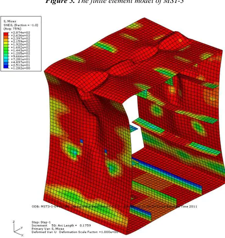
Figure 5. The finite element model of MST-3
Figure 6. Von-Mises stress plot of validation part in sagging condition
Figure 7. The ultimate longitudinal strength MUof MST model in sagging condition in case without residual stress
Figures 6 and 7 show the result of ultimate longitudinal strength MU of MST-3 model in sagging condition and Table
2 shows comparison of MU between experiment and FEM. It
can be observed that results of FEM are difference about 2% with experiment. That mean the prediction of ultimate longitudinal strength by FEM is true and accuracy.
Table 2.The ultimate longitudinal strength for MST-3 model
MU
(E+8 Nmm) Experiment FEM Only initial deflection
Initial deflection and residual stress Sagging 5.8840 5.9791 5.7611
Difference 1.6% - 2.09%
3.2. Nishihara MSD Model
The length of MSD model is also 540mm [3], therefore the overall length of finite element model is 3x540mm. The scantlings of cross section box girders show in Figure 8.
Figure 9. The ultimate longitudinal strength MU of MSD model in case without residual stress
Table 3. The ultimate longitudinal strength of MSD model
Sagging (E+8 Nmm) Hogging (E+8 Nmm)
Experiment
FEM
Experiment
FEM
Only initial deflection Initial deflection and residual stress
Only initial deflection
Initial deflection and residual stress
MU 5.9330 6.0781 5.9028 8.3847 8.3408 8.3117
Difference 2.4 % - 0.51 % - 0.5 % - 0.87 %
3.3. The 1/3-scale Frigate Model
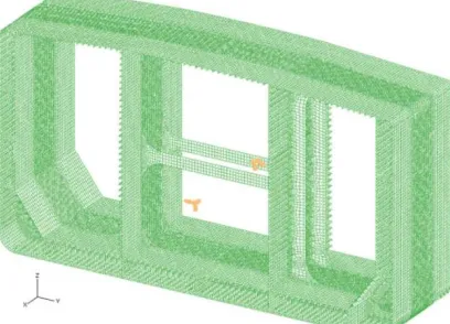
The 1/3-scale Frigate model was conducted by Dow [4], the total dimensions are 18m length, 4.1m breadth and 2.8m depth. The scantling shows in Figure10. The validation part is one frame space, equal 457.2 mm. Therefore the length of a finite element model is 3x457.2mm.
Figure 10. The cross section of the 1/3-scale Frigate model [4]
Figure 11. The finite element model of 1/3-scale Frigate
Table 4 shows the comparison of ultimate longitudinal strength MU between experiment and FEM. It showed that the
result of FEM is good agreement with experimental result.
Table 4. The ultimate longitudinal strength for 1/3-scale Frigate
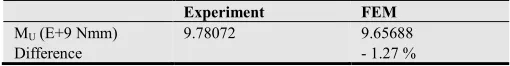
Experiment FEM MU (E+9 Nmm) 9.78072 9.65688
Figure 12. The ultimate longitudinal strength MU in sagging condition for 1/3-scale Frigate
The Figure 12 shows curves which performed the progressive bending moment by experimental results (red dot points) and FEM results (black line). Difference to other researchers, this study added the web frame in the finite element model (see in Figure 11), that is the reason why the FEM results are good agreement with experimental results within included in the post ultimate regime.
Through results between FEM and experiments are mentioned as above, from the laboratory model (Nishihara MST-3 for single bottom model, Nishihara MSD for double bottom model) to 1/3-scale Frigate model, it can be concluded that the FEM result is accuracy and reliability. Therefore, this FEM use to obtain the ultimate longitudinal strength for intact ship, in this paper is Double Hull VLCC given by ISSC 2000 [5].
3.4. Double Hull VLCC
The principal dimensions of Double Hull VLCC in ISSC 2000 [5] report are 315 m length, 58 m breadth and 30.3 m depth. The validation part is one frame space, equal 4980 mm. Therefore the length ofa finite element model is 3x4980 mm (see Figure 13).
Figure 13. The finite element model of Double Hull VLCC
Figure 14. The ultimate longitudinal strength of Double Hull VLCC
The curve in Figure 14 described relationship between reaction moment and end rotation of FEM analysis. The peak of curve is the value of ultimate longitudinal strength MU of
Double Hull VLCC in hogging (the red line) and sagging condition (the blue line).
4. Conclusions
In this research, by using the nonlinear FEM analysis through the modified RISK method in ABAQUS software, the ultimate longitudinal strength of intact ship under vertical bending moment was generated. Base on the result, these conclusions are obtained:
1.The three-dimesional finite element model has the length of three web frames spacing and the middle section of this model is the valid section for analysis. 2.The three-dimensional finite element model must to
have the web frame.
3.The ultimate longitudinal strength of intact ship could be performed by nonlinear FEM analysis. This method was taken into account for two Nishihara models, 1/3-scale Frigate model and Double Hull VLCC. The result which was obtained by FEM analysis had good agreement with experimental results, the difference results between two method is about 2 %.
References
[1] IACS, Common structural rules for double hull oil tankers., July 2010.
[2] ABAQUS/CAE User’s Manual, version 6.7-1, Published by the Hibbitt, Karlsson & Sorensen, Inc. 2000.
[3] S. Nishihara, “Analysis of ultimate strength of stiffened rectangular plate”, Journal of the Society of Naval Architects of Japan, Vol. 154, pp. 367-375 (in Japanese), 1983.
Girder under Longitudinal Bending”, Proceedings of the 15thInternational Offshore and Polar Engineering Conference, Seoul, Korea, June 19-24, 2005.
[9] M. Harada and T. Shigemi, “A Method for Estimating the Uncertainties in Ultimate Longitudinal Strength of Cross Section of Ship’s Hull Based on Nonlinear FEM”, 10th International Symposium on Practical Design of Ships and Other Floating Structures PRADS, Texas, USA, 2007. [10] H.G. Lee and J.S. Lee, “Ultimate longitudinal strength
assessment of ships’ hull girders”, Journal of Ship and Ocean Technology SOTECH, Vol. 12, No. 1, pp. 45-56, 2008. [11] H.K.K. Amlashi andT. Moan, “Ultimate strength analysis of a
bulk carrier hull girder under alternate hold loading condition – A case study. Part 1: Nonlinear finite element modeling and ultimate hull girder capacity”, Marine Structure 21, 321-352, 2008.
[12] Z. Shu and T. Moan, “Assessment of the hull girder ultimate strength of a bulk carrier using nonlinear finite element analysis”, Analysis and Design of Marine Structures, Guedes Soares & Das (editors), Taylor and Francis Group, London, 2009.
[13] Z. Shu and T. Moan, “Ultimate strength of a Capsize Bulk
Structures – Guedes Soares & Fricke (editors), Taylor & Francis Group, London, ISBN 978-0-415-67771-4, 2011. [16] O.F. Hughes, “Ship Structural Design: A Rationally-Based,
Computer-Aided, Optimization Approach”, John Wiley & Sons, 1983.
![Figure 1. The ship model applied a vertical bending moment [1]](https://thumb-us.123doks.com/thumbv2/123dok_us/8462471.1708855/1.595.48.284.624.726/figure-ship-model-applied-vertical-bending-moment.webp)
![Figure 3. Assumed initial deflections in stiffened plates [5]](https://thumb-us.123doks.com/thumbv2/123dok_us/8462471.1708855/2.595.309.547.298.401/figure-assumed-initial-deflections-stiffened-plates.webp)