DMI: A PBX perspective
by THOMAS F. STOREY AT&T Information Systems Denver, Colorado
ABSTRACT
For the past 20 to 30 years, the Private Branch Exchange (PBX) has provided an
efficient and effective means of communicating in the office environment. One of
the major reasons that PBXs and the interconnecting voice-oriented network are
Ubiquitous, of high quality, and implementable by many vendors is the existence of
technical standards defining the interface specifications between the nodes of the
network. OMI is a newly proposed standard for data communications that has the
potential to create for data what the existing standards have done for voice
commu-nications. In fact, much of this potential can be immediately realized, since the
physical level of the OMI protocol uses the standard OSl bit rate (1.544 Mb/s) and
it is directly compatible with the high-speed Tl digital facilities existing in North
America. In other words, there are billions of dollars in network facilities that OMI
can leverage on immediately.
The PBX is ideally positioned to enable OMI to solve many data networking
problems. The office environment is the hub of most data networking. The PBX,
because of the office's voice needs, is already central to an office's voice
communi-cations network. Therefore, the digital PBX has the opportunity to efficiently solve
both voice and data networking problems. For the data component, OMI is able to
provide a cost-effective, high-speed interface, interconnecting terminals to hosts,
and hosts to hosts on the customer's premises. In addition, the PBX is able to
improve dramatically this data connectivity by extending it over a large geographic
area. That is, individual 64
Kb/sOMI channels can be switched through the PBX
and onto standard long-haul digital facilities. The local area network provided by
OMI and the PBX can then become a wide area network that can access not only
an entire country but potentially the world.
ROLE OF THE PBX
For the past 20 to 30 years, the private branch exchange (PBX) has provided an efficient and effective means of com-municating in the office environment. The term PBX refers to a switching system (exchange) located on a customer's prem-ises (private branch) that provides interconnection among ter-minals and facilitates access to the external network. The PBX's counterparts in the local and long-distance network are the central office switch and the toll trunk switcher. These switches, together with the interconnecting facilities, have created a network in the U.S. that is not only a technological marvel but the envy of the world. From any PBX network terminal a high-quality, voice-oriented connection can be set up instantly to more than 200 million end points anywhere in the country.
The network, which has been optimized for voice connec-tions, also has been used extensively to transport data be-tween terminals and hosts as well as bebe-tween hosts. Modems are used to convert the per-channel digital bit streams from these devices to analog signals that permit the transmission of the data onto a connection that would normally carry voice. However, with the rapid growth of PBX data end points in recent years, and the limitations created with modems, it is desirable to transmit the digital bit streams between the termi-nal and host end points transparently within the PBX. It is . also desirable to access the network directly with the digital bit streams. Digital PBXs have made this possible.
A digital PBX uses a digital network fabric. That is, it performs its connection function by switching the digital bit stream received directly from each originating end point to each terminating end point. Digital switching in the PBX has many advantages, including the ability to increase the trans-mission rates between the end points dramatically and cost effectively. The latter also applies to the network access interface.
EFFECT OF STANDARDS ON THE VOICE NETWORK
One major reason that the existing voice-oriented network is widespread, of high quality, and implementable by many ven-dors is the existence of technical standards that define the interface specifications between the nodes of the network. AT&T has had a history of creating network technical stan-dards and making them available to all so that there can be one network. In particular, the United States Independent Telephone Association (USITA) and AT&T have collec-tively contributed over the years to the "Notes on Distance
DMI: A PBX Perspective 627
Dialing," which have provided technical data required by de-signers and engineers to design and plan the existing network in areas such as the numbering plan, the switching plan, equipment, signaling, and in network management, transmis-sion, and maintenance.
DMI DATA NETWORKING STANDARD
The digital multiplexed interface (DMI) is a proposed stan-dard for data communications that has the potential to create for data what the existing standards have done for voice com-munications. In fact, much of this potential can be realized immediately, because the physical level of the DMI protocol uses the standard DSl bit rate (1.544 Mb/s) and it is directly compatible with North American high-speed Tl digital facili-ties. In other words, there are billions of dollars' worth of net-work facilities that DMI can use immediately.
DMI also is consistent with international standards; the North American standard is used in Japan. The international telecommunications organization, CCITT, is actively consid-ering the Integrated Services Digital Network (ISDN) stan-dards proposals. DMI has incorporated the ISDN stanstan-dards wherever possible. At the physical level, DMI supports both North American (1.544 Mb/s) and European (2.048 Mb/s) high-speed digital facility line rates. This provides 24 and 32 64-Kb/s channels, respectively. For the message base control channel the protocol is the same as the CCITT standard, and it is hoped that CCITT will adopt the DMI mode 3 protocol for the ISDN data channels.
The PBX is ideally positioned to enable DMI to solve many data networking problems. That is, the office environment is the hub of most data networking. The PBX, because of the office's voice needs, is already central to most office commu-nications networks. Therefore, the digital PBX has the oppor-tunity to solve both voice and data networking problems. For the data component, DMI is able to provide a cost-effective, high-speed interface, connecting terminals to hosts and hosts to hosts on the customer's premises. In addition, the PBX is able to improve dramatically this data connection by extend-ing it over a large geographic area. That is, individual 64-Kb/s DMI channels can be switched through the PBX and onto standard long-haul digital facilities. The local area network provided by DMI and the PBX can then become a wide area network that can access not only an entire country but poten-tially the world. For the existing voice implementation of the network, the features and capabilities are already well estab-lished. With the PBX providing the networking for data as well as voice, several significant benefits can also be realized including a common network and control structure providing
common maintenance and administration, a common access to both the work station and the network, and the opportunity to provide integrated voice-data services (because simulta-neous access is available to both).
PBX ARCHITECTURE
The PBX provides a reliable, easily configurable switching network fabric that enables interconnection of voice or data terminals within the office. It also permits the interconnection of PBX end points to the network. The PBX makes the inter-connections by setting up a two-way circuit for the duration of a call between the two end points involved. Up until a few years ago, the circuit switch connection transmitted the analog representation of the voice or data connection. Today, the PBX uses a digital representation of the signal from the end points. The switch fabric therefore transmits a digital bit stream. For voice-oriented end points the analog signal is sampled at 8 KHz and each sample is represented by an 8-bit code. It therefore takes 64 Kb/s to represent a voice connec-tion. For data end points, a 64-Kb/s switched data channel is not only a basic switchable channel but it is easy to implement. The PBX digital swtich fabric also can be configured for simul-taneous switching of very high bandwidth channels that are multiples of 64-Kb/s channels (i.e., 384 Kb/s or 1.544 Mb/s). Each physical end point in a PBX environment normally has two terminals, one for voice and one for data. It is therefore advantageous to have at least 128 Kb/s and a control channel at every end point.
Data networking with DMI therefore has a major advan-tage to draw on, the PBX itself. The modern PBX can im-prove the implementation of a cost-effective, widespread, and
reliable data network for the office. It also can provide con-nection to the rest of the world. The following sections outline some of the attributes of a modern PBX and the design tech-nology that should enable the PBX and its DMI interface to achieve the attributes stated above.
PBX Switching Technology
PBX switching systems have a rich design base and a history of using the most up-to-date hardware and software to create automated and reconfigurable networks that connect thou-sands of end points. These systems operate in real time, are capable of high performance, often are fault tolerant, and are designed to meet the needs of the office environment. AT&T Information Systems' System 85 implements several capabili-ties (Figure 1).
The system uses a high-performance, bit-sliced, common control processor (501 CC) that can be duplicated for reli-ability. The duplicated processor, a cache memory, many megawords of random access memory, and a nonvolatile bulk storage subsystem all have built-in error detection and, in some cases, error correction. The processor and its subsys-tems can be reconfigured automatically in real time, without loss of service. In addition, the entire system can be diagnosed to the circuit pack (replaceable entity) level, again without service interruption. The entire duplicated system has a down-time objective of three minutes per year.
The switching network consists of two basic building blocks: a time slot interchange (TSI) module and a center-stage time multiplex switch (TMS). The TSI switches digital bit streams arriving from terminal end points by reordering the time se-quence of the bit streams received. The reordered digital bit streams are then sequenced onto the digital highways to
501CC
FISER OPTICS OR TRIA><
<4- MHZ
TS. MODULE
FISER OPTICS .32 MHZ
TMS (CENTER STAGE
SWITCH)
TSI MODULE
.31 MODULES 15.36 PORTS
return to the appropriate terminal end points. The TMS connects modules with one another and performs a space-switching function by directly connecting up to 31 TSI mod-ules at any given time. Because this space-switching function is multiplexed, the TMS is reconfigured millions of times each second.
Individual terminals are connected by twisted pair cables to port circuits in a TSI module that can be 5000 feet away. For normal digital end points these twisted pair cables carry data at 160 Kb/s. Port circuits format the digital bit streams and place them on the high-speed digital highways terminating on the TSI. The TSI has a switching capacity of 65 Mb/s. The capacity of the TMS is 1024 Mb/s. The TSIs are connected to the TMS by a 32-Mb/s fiber optic link that can be 13,000 feet long.
The digital switching network fabric has the same fault-tolerant capabilities as the processor complex. All the TSIs, the TMS, and their interconnecting fiber optic links can be duplicated. Built-in error detection, error recovery, and diag-nostics permit automatic reconfiguration under error condi-tions. They also allow easy location and replacement of failing circuit entities. For routine maintenance of redundant units, the system is even able to switch from the on-line to off-line network modules without missing a single bit passing through the network.
In addition to the 32-Mb/s fiber optic links, the system takes advantage of the latest in high-speed logic and both custom and off-the-shelf VLSI devices. For example, 256-K memory parts are used in the common control, custom VLSI in the port circuits, and high-speed ECL logic in the TMS. BENEFITS OF PBX VOICE-DATA INTEGRATON Because the PBX has a large installed base that currently implements a multiplicity of voice functions it provides an opportunity not only to leverage data implementations from the existing voice network but also to develop synergies be-tween voice and data functions on the PBX.
Installed PBX Base
Digital PBXs are being installed at a rapid rate, about 10,000 systems in 1985 in the U.S. alone. DMI allows efficient connection of host computers to these PBXs and in tum to the many terminal end points attached to these same PBXs.
Common Access to Long-Distance Network
The PBX provides an efficient means of connection to the long-distance network. PBXs are directly attached to the net-work, often with digital facilities. This access and the trans-mission over long distances is expensive. DMI data channels can share access and transmission costs with the digitized voice channels that traverse this interface.
Installed Network Facility Base
The long-distance network is rapidly becoming digital. DMI is directly compatible with this vast resource because the
phys-DMI: A PBX Perspective 629
icallayer of the DMI protocol is identical to the North Amer-ican T1 digital facility standard.
Installed Building Wiring Base
In most offices, huge investments have already been made in twisted pair copper wire that connects telephone station sets to PBXs, both old and new. This same twisted pair wire can be used to transmit high-speed digital signals from work stations to the PBX.
Voice-Data Feature Integration
The ability to use shared resources for voice and data also offers the opportunity to develop features that take advantage of the simultaneous access to voice and data information.
ISDN Directions
DMI is directly compatible with the ISDN standards. In addition, it should not be long before ISDN network stan-dards are accepted for PBX-to-PBX and PBX-to-network in-terfaces, not only in the U.S., but worldwide. When this hap-pens, DMI's advantages will multiply for many of the reasons outlined above.
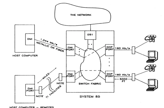
DMI ARCHITECTURE AND DESIGN IN THE PBX To outline the architecture of the DMI interface in a PBX, the implementation of System 85 will be highlighted. System 75's implementation is similar. Figure 2 shows a system level view of the connection between terminal end points and host com-puters and between one host computer and another. It also illustrates the interface to the network.
PBX to Host Computer
DMI defines the PBX-to-host-computer interface. For do-mestic implementation, the physical level is a 1.544-Mb/s bit stream that uses the standard North American T1 framing formats and provides 23 64-Kb/s data channels and one 64-Kb/s common signaling channel. The output of a DMI port on either the PBX or the host computer can interface directly to external facilities (no digital channel banks), providing an ability to use this interface easily at long distances (thousands of miles) over digital facilities.
For a direct interface to the external network, the FCC requires the use of a network channel terminating equipment (NCTE) device. The NCTE terminates the repeatered T1 line, provides T1 maintenance capabilities, and provides a DS1-compatible interface to the PBX or host computer. The maximum distance from the NCTE to the PBX or the host is 655 feet over twisted pair cable. A special twisted pair shielded cable is required for this interface.
For use in an office, the DS1 metallic interface can extend 1310 feet between the PBX and the host. Again, the special
THE NETWORK
OMI
HOST COMPUTER
OMI PORT
NCTE" SYSTEM 85
HOST COMPUTER - REMOTED
Figure 2-System level view
twisted pair shielded cable is required. A fiber optic interface option from the DMI port will permit DMI to extend 2-km for large buildings or complexes.
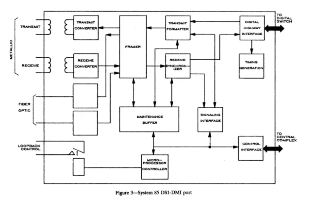
Figure 3 is a detailed block diagram of the DMI port design in the PBX. The entire interface is contained on a single, 8-by 14-inch circuit pack. The major sections of the DMI inter-face are the DS11.544-Mb/s line interinter-face (implemented with transformers and a VLSI DS1 chip set), the fiber optic link interface, the interface to the high-speed digital . bit stream highways that connect the DMI port to the TSI switch entity, the interface to common control of the digital switch fabric, and a microprocessor control complex to provide a variety of functions on the DMI port. The microprocessor functions include processing the signaling information in the 24th chan-nel, providing the per-channel control association with each data channel, initiating start-up, and setting default parame-ters for the port. The microprocessor also performs error monitoring and maintenance testing both in real time and on demand for many functions both on this port and on the connected facilities.
For the metallic implementation, the DMI 1.544-Mb/s bit stream arrives at the receive input. Passing through the re-ceive transformer, it then encounters in sequence the rere-ceive converter, the framer, and the receive synchronizer. These devices convert the T1 alternate mark inversion (AMI) signal into a parallel data format, recover clock from the incoming bit stream, and identify the DS1 frame boundaries. These
devices also double-buffer the incoming data streams to elim-inate any loss of data that might occur because of phase jitter between the DS1 line clock and the PBX network clock. In addition, they provide a 32, 64-Kb/s-channel format for the data that are transmitted to the switch network. The 32-channel interface to the switch allows the same basic design to be used both for domestic (24) and for international (32) facility interfaces. In the transmit direction the inverse func-tions are performed-. The ma.lntenance buffer device provides an 8-bit microprocessor bus on one side and a serial channel interface to the DS1 chip set on the other. The serial channel provides the access and the capability to run both in-serivce and out-of-service error detection and maintenance routines on the DMI port. The maintenance buffer also monitors in-service facility alarms and records the number of misframes and slips on the DMI facility.
The fiber optic interface operates in the same manner as the metallic interface except that a fiber optic transmitter and receiver replace the transformers and the transmitter and re-ceive converters, respectively.
In the DMI interface at the PBX, the level two and level three functions of the DMI protocol are not performed. The HDLC data streams are transmitted directly through the DMI port and the switching network to the terminal or host com-puter end points, where these levels of the protocol are termi-nated. For PBX terminals that are not compatible with DMI protocols, an adapter or protocol converter is needed. This
-TRANS ... IT
-RECEIV E
-FIBER [ OPTIC
K L-OOPBAC
CONTR
OL-] [
TRANSMIT CONVERTItR] [
RECEIVE CONVERTERA~
TRANSMIT
-
f4--
f'ORMATl"ER..-FRAMER
+
RECEIVE..
CHRON-...
IZER---
-~
r--r
,
UAlNTENANCE SIGNALING
-
BUFFER INTERFACe:1
MICRO-PROCESSOR CONTROLLER
Figure >-System 85 DSI-DMI port
DMI: A PBX Perspective 631
DIGITAL. HIGHWAY 1..6...
r..-INTERFACE
•
TIMING GENERATIONCONTROL
""'--INTERFACE
...-TO DIGI TAl..TCH SWI
~
~
TO CEN
TRAL-MPLEX CO
...
~adapter can be put in series with the DMI interface or it can be pooled and switched into DMI connections as shown in Figure 4.
interfaces to the network, except for the firmware that con-trols the details of the network signaling and sequencing patterns.
PBX to Network
The same physical interface described for the D MI host port in the PBX· can also be used for the PBX port that PBX
64 KBIT TRANSPARENT
CONY. OMI
PBX to Terminal
The PBX-to-terminal interface probably will be a little dif-ferent for each PBX vendor. However, there will typically be
__ ~ ___________ O_M_I __ U_N_K_TRANSPARENT CONY. OMI
OMI
LINK TRUNKSIOE
1 - - - -ADAPTER OMI UNK POOLEO i---AOAPTER
some areas of commonality: one or two 64-Kb/s data channels
for each work station, a moderate speed control channel (8- or
16-Kb/s) and a physical line interface that allows these
chan-nels and direct current power to be multiplexed onto twisted pair copper wires and transmitted thousands of feet from the PBX switch.
In System 75/85, the digital terminal line interface is defined
with a protocol called DCP (digital communications proto-col), which initially was chosen to be compatible with the ISDN terminal interface. It is therefore similar to the ISDN standard, but in the interval since the DCP design was com-pleteda few years ago, the ISDN standards have been modi-fied. The DCP line rate is 160 Kb/s; two 64-Kb/s channels (one
for voice and one for data), 8 Kb/s for control, with the
re-maining bandwidth for framing. The DCP line can support digital end points up to 5000 feet from the PBX. DCP sup-ports only. point-to-point line terminations.
COST IS THE BENEFIT
The multiplexed nature of the DMI interface between the PBX and the host computer will provide a major cost im-provement compared with current methods of interconnec-tion. Individual lines and the associated interface hardware now are required for every connection, both at the PBX and at the host end. Typically it will be more cost effective to use a 23-channel DMI link rather than four or five individual links using modems and per-channel hardware. Therefore, the im-plementation of large numbers of terminals or personal com-puters connecting to a host will be cost efficient.
DMI also has many feature attributes that will greatly en-hance the utility of the interface:
1. OMI offers a direct interface to standard T1 facilities, which "remote" the PBX-to-host multiplexed connec-tion.
2. DMI also provides the ability to connect equipment from several vendors to one standard interface.
3. DMI protocol options offer a range of HDLC-compatible alternatives for transmition of high-speed digital data over a large embedded base of digital facili-ties. DMI mode 3 will be particularly attractive because of its error detection and error correction capability, its ability to implement statistical multiplexing on DMI links, and the simplicity and cost effectiveness of termi-nating the protocol at terminal end points.
SUMMARY
DMI has been proposed by AT&T Information Systems as a standard to help create a universal interface that will allow efficient networking of computers through PBXs. The large embedded base of digital PBXs and the vast long-distance network to which PBXs have access, make the PBX an ex-tremelypowerful networking vehicle. Today's PBX can rou-tinely switch 64-Kb/s channels; many can switch Mb/s
chan-nels if so required.
AT&T Information Systems and Hewlett-Packard have been working together for the past year to ensure a DMI interface that can be implemented universally. This has in-cluded working with Rockwell International and AT&T Tech-nologies to ensure the availability of VLSI support to facilitate a straightforward and cost-effective design of the DMI inter-faces both at the PBX and the host computer. Design implementation details and VLSI descriptions are provided to all DMI licensees at the DMI User's Group Meetings held every few months. It is expected that the availability, the technical content, and the many capabilities of the DMI specification, together with VLSI device support and the implementation details provided, will enable DMI to become a universal data communications standard. This standard should benefit all PBX and host computer vendors. Most important, it should soon provide the users with a class of data service that rivals the voice services offered today by the PBX and the long-distance network.