80-00156-01, Rev. D
MegaRAID SAS Software
USER’S
GUIDE
This document contains proprietary information of LSI Corporation. The informa-tion contained herein is not to be used by or disclosed to third parties without the express written permission of an officer of LSI Corporation.
Document 80-00156-01, Rev. D (April 2008)
This document describes the LSI Corporation’s MegaRAID Storage Manager software. This document will remain the official reference source for all revisions/releases of this product until rescinded by an update.
LSI Corporation reserves the right to make changes to any products herein at any time without notice. LSI does not assume any responsibility or liability arising out of the application or use of any product described herein, except as expressly agreed to in writing by LSI; nor does the purchase or use of a product from LSI convey a license under any patent rights, copyrights, trademark rights, or any other of the intellectual property rights of LSI or third parties.
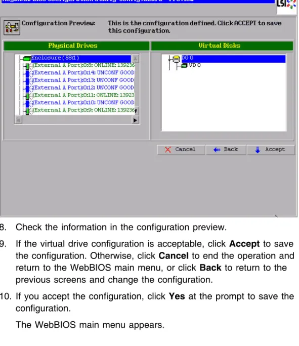
Copyright © 2005-2008 by LSI Corporation. All rights reserved. TRADEMARK ACKNOWLEDGMENT
LSI, the LSI logo design, iBBU, MegaRAID, and MegaRAID Storage Manager are trademarks or registered trademarks of LSI Corporation. Microsoft and Windows are trademarks or registered trademarks of Microsoft Corporation. Linux is a registered trademark of Linus Torvalds. Intel and Pentium are registered trademarks of Intel Corporation. SCO and SCO UnixWare are registered trademarks and OpenServer is a trademark of the SCO Group, Inc. This product includes software developed by the Apache Software Foundation
(http://www.apache.org/). All other brand and product names may be trademarks of their respective companies.
KL/CD
To receive product literature, visit us at http://www.lsi.com.
For a current list of our distributors, sales offices, and design resource centers, view our web page located at
MegaRAID SAS Software User’s Guide iii Copyright © 2005-2008 by LSI Corporation. All rights reserved.
Preface
This document explains how to use the MegaRAID Storage Manager™ software, WebBIOS, and Command Line Interface (CLI) utilities to configure, monitor, and maintain MegaRAID® SAS RAID controllers and the storage-related devices connected to them.
Audience
This document assumes that you are familiar with SAS controllers and configuration utilities. The people who benefit from this book are network administrators who need to create storage configurations on LSI SAS controllers.
Organization
This document has the following chapters and appendixes:
•
Chapter 1, “Introduction to RAID,” describes RAID (Redundant Array of Independent Disks), RAID functions and benefits, RAIDcomponents, RAID levels, and configuration strategies. In addition, it defines the RAID availability concept, and offers tips for configuration planning.
•
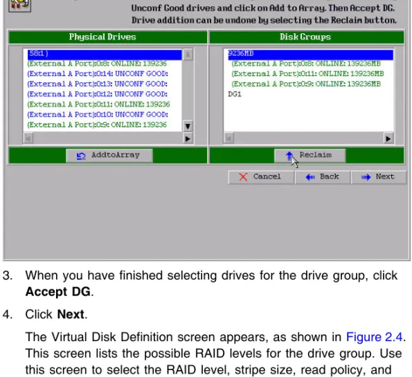
Chapter 2, “WebBIOS Configuration Utility,” explains how to use the pre-boot WebBIOS Configuration Utility to create and manage storage configurations.•
Chapter 3, “MegaRAID Command Tool,” explains how to use the MegaRAID Command Tool to create and manage storageconfigurations. The MegaRAID Command Tool is a CLI application for SAS.
•
Chapter 4, “MegaRAID Storage Manager Overview and Installation,” introduces the main features of MegaRAID Storage Manager software and explains how to install it.•
Chapter 5, “MegaRAID Storage Manager Window and Menus,” describes the layout of the MegaRAID Storage Manager window and lists the available menu options.•
Chapter 6, “Configuration,” describes how to use the MegaRAID Storage Manager software to configure or reconfigure storage devices, how to save configurations, and how to apply saved configurations to a controller.•
Chapter 7, “Monitoring System Events and Storage Devices,” explains how the MegaRAID Storage Manager software monitors the status of storage configurations and devices and displays information about them.•
Chapter 8, “Maintaining and Managing Storage Configurations,” describes the MegaRAID Storage Manager maintenance functions for virtual drives and other storage devices.•
Appendix A, “Events and Messages,” provides descriptions of the MegaRAID Storage Manager events.•
Appendix B, “Glossary,” contains definitions of storage-related terms. ConventionsNote: Notes contain supplementary information that can have an effect on system performance.
Caution: Cautions are notifications that an action has the potential to adversely affect equipment operation, system performance, or data integrity.
Preface v Copyright © 2005-2008 by LSI Corporation. All rights reserved.
Revision History
Document
Number DateRevision Remarks
80-00156-01 Rev. D April 2008 Updated the RAID overview section. Updated the WebBIOS Configuration Utility and the MegaRAID Storage Manager. Updated the MegaCLI commands.
80-00156-01 Rev. C July 2007
Version 2.1 Updated operating system support for MegaCLI. 80-00156-01 Rev. B June 2007
Version 2.0 Updated the WebBIOS Configuration Utility and the Mega-RAID Storage Manager. Updated the MegaCLI commands. Added the RAID introduction chapter.
80-00156-01 Rev. A August 2006
Version 1.1 Corrected the procedure for creating RAID 10 and RAID 50 drive groups in the WebBIOS Configuration Utility. DB15-000339-00 December 2005
MegaRAID SAS Software User’s Guide vii Copyright © 2005-2008 by LSI Corporation. All rights reserved.
Contents
Chapter 1
Introduction to RAID
1.1 RAID Description 1-1
1.2 RAID Benefits 1-1
1.3 RAID Functions 1-1
1.4 Components and Features 1-2
1.4.1 Physical Array 1-2
1.4.2 Virtual Drive 1-2
1.4.3 RAID Drive Group 1-3
1.4.4 Fault Tolerance 1-3
1.4.5 Consistency Check 1-5
1.4.6 Copyback 1-5
1.4.7 Background Initialization 1-6
1.4.8 Patrol Read 1-7
1.4.9 Disk Striping 1-7
1.4.10 Disk Mirroring 1-8
1.4.11 Parity 1-9
1.4.12 Disk Spanning 1-10
1.4.13 Hot Spares 1-11
1.4.14 Disk Rebuilds 1-13
1.4.15 Rebuild Rate 1-14
1.4.16 Hot Swap 1-14
1.4.17 Drive States 1-14
1.4.18 Virtual Drive States 1-15
1.4.19 Enclosure Management 1-16
1.5 RAID Levels 1-16
1.5.1 Summary of RAID Levels 1-16
1.5.2 Selecting a RAID Level 1-17
1.5.4 RAID 1 1-18
1.5.5 RAID 5 1-19
1.5.6 RAID 6 1-20
1.5.7 RAID 10 1-22
1.5.8 RAID 50 1-23
1.5.9 RAID 60 1-24
1.6 RAID Configuration Strategies 1-26
1.6.1 Maximizing Fault Tolerance 1-27
1.6.2 Maximizing Performance 1-28
1.6.3 Maximizing Storage Capacity 1-30
1.7 RAID Availability 1-31
1.7.1 RAID Availability Concept 1-31
1.8 Configuration Planning 1-32
1.8.1 Number of Drives 1-33
1.8.2 Drive Group Purpose 1-33
Chapter 2
WebBIOS Configuration Utility
2.1 Overview 2-1
2.2 Starting the WebBIOS CU 2-2
2.3 WebBIOS CU Main Screen Options 2-3
2.4 Creating a Storage Configuration 2-5 2.4.1 Selecting the Configuration with the Configuration
Wizard 2-6
2.4.2 Using Auto Configuration 2-7
2.4.3 Using Custom Configuration 2-8 2.5 Viewing and Changing Device Properties 2-50 2.5.1 Viewing and Changing Controller Properties 2-51 2.5.2 Viewing and Changing Virtual Drive Properties 2-54
2.5.3 Viewing Drive Properties 2-55
2.5.4 Viewing Battery Backup Unit Information 2-57 2.6 Viewing System Event Information 2-58
2.7 Managing Configurations 2-60
2.7.1 Running a Consistency Check 2-60
2.7.2 Deleting a Virtual Drive 2-60
2.7.3 Importing or Clearing a Foreign Configuration 2-61 2.7.4 Migrating the RAID Level of a Virtual Drive 2-65
Contents ix Copyright © 2005-2008 by LSI Corporation. All rights reserved.
Chapter 3
MegaRAID Command Tool
3.1 Product Overview 3-2
3.2 Novell, SCO, and Solaris Operating System Support 3-3 3.3 MegaCLI Version 1.00.22 Upgrade for Linux 3-4 3.4 Command Line Abbreviations and Conventions 3-4 3.4.1 Abbreviations Used in the Command Line 3-5
3.4.2 Conventions 3-5
3.5 Adapter Property-Related Options 3-6 3.5.1 Display Adapter Properties 3-6 3.5.2 Display Number of Controllers Supported 3-7 3.5.3 Enable or Disable Automatic Rebuild 3-7
3.5.4 Flush Adapter Cache 3-7
3.5.5 Set Adapter Properties 3-8
3.5.6 Display Specified Adapter Properties 3-9
3.5.7 Set Factory Defaults 3-10
3.5.8 Set SAS Address 3-10
3.5.9 Set Time and Date on Adapter 3-10 3.5.10 Display Time and Date on Adapter 3-10 3.6 Patrol Read-Related Adapter Properties 3-11
3.6.1 Set Patrol Read Options 3-11
3.6.2 Set Patrol Read Delay Interval 3-11
3.7 BIOS-Related Properties 3-12
3.7.1 Set or Display Bootable Virtual Drive ID 3-12 3.7.2 Select BIOS Status Options 3-12 3.8 Battery Backup Unit-Related Properties 3-13
3.8.1 Display BBU Information 3-13
3.8.2 Display BBU Status Information 3-13
3.8.3 Display BBU Capacity 3-14
3.8.4 Display BBU Design Parameters 3-15 3.8.5 Display Current BBU Properties 3-15
3.8.6 Start BBU Learning Cycle 3-16
3.8.7 Place Battery in Low-Power Storage Mode 3-16
3.8.8 Set BBU Properties 3-16
3.9 Options for Displaying Logs Kept at Firmware Level 3-17
3.9.1 Event Log Management 3-17
3.10 Configuration-Related Options 3-18 3.10.1 Create a RAID Drive Group from All Unconfigured Good
Drives 3-18
3.10.2 Add RAID 0, 1, 5, or 6 Configuration 3-19 3.10.3 Add RAID 10, 50, or 60 Configuration 3-21 3.10.4 Clear the Existing Configuration 3-21 3.10.5 Save the Configuration on the Adapter 3-22 3.10.6 Restore the Configuration Data from File 3-22 3.10.7 Manage Foreign Configuration Information 3-22 3.10.8 Delete Specified Virtual Drive(s) 3-23
3.10.9 Display the Free Space 3-23
3.11 Virtual Drive-Related Options 3-24 3.11.1 Display Virtual Drive Information 3-24 3.11.2 Change the Virtual Drive Cache and Access Parameters
3-24
3.11.3 Display the Virtual Drive Cache and Access Parameters 3-25
3.11.4 Manage Virtual Drives Initialization 3-25 3.11.5 Manage a Consistency Check 3-26 3.11.6 Manage a Background Initialization 3-26 3.11.7 Perform a Virtual Drive Reconstruction 3-27 3.11.8 Display Information about Virtual Drives and Drives3-27 3.11.9 Display the Number of Virtual Drives 3-27
3.12 Drive-Related Options 3-28
3.12.1 Display Drive Information 3-28 3.12.2 Set the Drive State to Online 3-28 3.12.3 Set the Drive State to Offline 3-28 3.12.4 Change the Drive State to Unconfigured Good 3-29
3.12.5 Change Drive State 3-29
3.12.6 Manage a Drive Initialization 3-30
3.12.7 Rebuild a Drive 3-30
3.12.8 Locate the Drive(s) and Activate LED 3-31 3.12.9 Mark the Configured Drive as Missing 3-31 3.12.10 Display the Drives in Missing Status 3-31 3.12.11 Replace the Configured Drives and Start an Automatic
Rebuild 3-31
3.12.12 Prepare the Unconfigured Drive for Removal 3-32 3.12.13 Display Total Number of Drives 3-32
Contents xi Copyright © 2005-2008 by LSI Corporation. All rights reserved.
3.12.14 Display List of Physical Devices 3-32
3.13 Enclosure-Related Options 3-33
3.14 Flashing the Firmware 3-33
3.14.1 Flash the Firmware with the ROM File 3-33 3.14.2 Flash the Firmware in Mode 0 with the ROM File 3-34
3.15 SAS Topology 3-34
3.16 Diagnostic-Related Options 3-35
3.16.1 Start Adapter Diagnostics 3-35
3.16.2 Start Battery Test 3-35
3.16.3 Start NVRAM Diagnostic 3-35
3.17 Miscellaneous Options 3-36
3.17.1 Display the MegaCLI Version 3-36 3.17.2 Display Help for MegaCLI 3-36 Chapter 4
MegaRAID Storage Manager Overview and Installation
4.1 Overview 4-1
4.1.1 Creating Storage Configurations 4-1 4.1.2 Monitoring Storage Devices 4-2 4.1.3 Maintaining Storage Configurations 4-2 4.2 Hardware and Software Requirements 4-2
4.3 Installation 4-3
4.3.1 Installing MegaRAID Storage Manager Software on
Microsoft Windows 4-3
4.3.2 Installing MegaRAID Storage Manager Software for
Linux 4-8
4.3.3 Linux Error Messages 4-9
4.4 MegaRAID Storage Manager Support and Installation on VMWare 4-9
4.4.1 Installing MegaRAID Storage Manager (MSM) for
VMWare 4-10
4.4.2 Uninstalling MegaRAID Storage Manager 4-10 4.4.3 Uninstalling MegaRAID Storage Manager for VMWare
Chapter 5
MegaRAID Storage Manager Window and Menus
5.1 Starting MegaRAID Storage Manager Software 5-1 5.2 MegaRAID Storage Manager Window 5-4 5.2.1 Physical/Logical View Panel 5-5 5.2.2 Properties/Operations/Graphical View Panel 5-6
5.2.3 Event Log Panel 5-8
5.2.4 Menu Bar 5-9
Chapter 6 Configuration
6.1 Creating a New Storage Configuration 6-1 6.1.1 Understanding Virtual Drive Parameters 6-3
6.1.2 Using Auto Configuration 6-5
6.1.3 Using Guided Configuration 6-7 6.1.4 Using Manual Configuration: RAID 0 6-10 6.1.5 Using Manual Configuration: RAID 1 6-12 6.1.6 Using Manual Configuration: RAID 5 6-14 6.1.7 Using Manual Configuration: RAID 6 6-15 6.1.8 Using Manual Configuration: RAID 10 6-16 6.1.9 Using Manual Configuration: RAID 50 6-17 6.1.10 Using Manual Configuration: RAID 60 6-18
6.2 Adding Hot Spare Drives 6-20
6.3 Changing Adjustable Task Rates 6-21 6.4 Changing Virtual Drive Properties 6-24 6.5 Changing a Virtual Drive Configuration 6-25 6.5.1 Adding a Drive to a Configuration 6-26 6.5.2 Removing a Drive from a Configuration6-27 6.5.3 Changing the RAID Level of a Configuration 6-28
6.6 Deleting a Virtual Drive 6-28
6.7 Saving a Storage Configuration to Drive 6-29 6.8 Clearing a Storage Configuration from a Controller 6-29 6.9 Adding a Saved Storage Configuration 6-30
Contents xiii Copyright © 2005-2008 by LSI Corporation. All rights reserved.
Chapter 7
Monitoring System Events and Storage Devices
7.1 Monitoring System Events 7-1
7.2 Configuring Event Notifications 7-3 7.2.1 Setting Alert Delivery Rules 7-4 7.2.2 Changing the Event Severity 7-5
7.2.3 Defining Exceptions 7-6
7.2.4 Selecting Email Settings 7-8
7.3 Monitoring Controllers 7-10
7.4 Monitoring Drives 7-12
7.5 Running a Patrol Read 7-14
7.6 Monitoring Virtual Drives 7-16
7.7 Monitoring Enclosures 7-18
7.8 Monitoring Battery Backup Units 7-19
7.8.1 Battery Learn Cycle 7-21
7.9 Monitoring Rebuilds and Other Processes 7-21 Chapter 8
Maintaining and Managing Storage Configurations
8.1 Initializing a Virtual Drive 8-1
8.2 Running a Consistency Check 8-2
8.3 Scanning for New Drives 8-3
8.4 Rebuilding a Drive 8-3
8.5 Making a Drive Offline or Missing 8-4
8.6 Upgrading the Firmware 8-5
Appendix A
Events and Messages Appendix B
Glossary
Contents xv Copyright © 2005-2008 by LSI Corporation. All rights reserved.
Figures
1.1 Example of Disk Striping (RAID 0) 1-7 1.2 Example of Disk Mirroring (RAID 1) 1-8 1.3 Example of Distributed Parity (RAID 5) 1-9
1.4 Example of Disk Spanning 1-10
1.5 RAID 0 Drive Group Example with Two Drives 1-18
1.6 RAID 1 Drive Group 1-19
1.7 RAID 5 Drive Group with Six Drives 1-20 1.8 Example of Distributed Parity across Two Blocks in a Stripe
(RAID 6) 1-22
1.9 RAID 10 Level Virtual Drive 1-23
1.10 RAID 50 Level Virtual Drive 1-24
1.11 RAID 60 Level Virtual Drive 1-26
2.1 WebBIOS CU Main Screen 2-3
2.2 WebBIOS Configuration Wizard Screen 2-6 2.3 WebBIOS Disk Group Definition Screen 2-9 2.4 WebBIOS Virtual Disk Definition Screen 2-10
2.5 RAID 0 Configuration Preview 2-13
2.6 WebBIOS Disk Group Definition Screen 2-14 2.7 WebBIOS Virtual Disk Definition Screen 2-15
2.8 RAID 1 Configuration Preview 2-18
2.9 WebBIOS Disk Group Definition Screen 2-19 2.10 WebBIOS Virtual Disk Definition Screen 2-20
2.11 RAID 5 Configuration Preview 2-23
2.12 WebBIOS Disk Group Definition Screen 2-25 2.13 WebBIOS Virtual Disk Definition Screen 2-26
2.14 RAID 6 Configuration Preview 2-29
2.15 WebBIOS Disk Group Definition Screen 2-31 2.16 WebBIOS Span Definition Screen 2-32 2.17 WebBIOS Virtual Disk Definition Screen 2-33 2.18 RAID 10 Configuration Preview 2-36 2.19 WebBIOS Disk Group Definition Screen 2-38 2.20 WebBIOS Span Definition Screen 2-39 2.21 WebBIOS Virtual Disk Definition Screen 2-40 2.22 RAID 50 Configuration Preview 2-43 2.23 WebBIOS Disk Group Definition Screen 2-45 2.24 WebBIOS Span Definition Screen 2-46
2.25 WebBIOS Virtual Disk Definition Screen 2-47 2.26 RAID 60 Configuration Preview 2-50 2.27 First Adapter Properties Screen 2-51 2.28 Second Adapter Properties Screen 2-52
2.29 Virtual Disk Screen 2-54
2.30 Physical Drive Screen 2-56
2.31 Battery Module Screen 2-58
2.32 Event Information Screen 2-59
2.33 Foreign Configuration Screen 2-62
2.34 Foreign Configuration Preview Screen 2-62
4.1 Customer Information Screen 4-4
4.2 Setup Type Screen 4-5
4.3 Setup Type Screen 4-6
4.4 Custom Setup Screen 4-7
4.5 Server Screen 4-8
5.1 Select Server Window 5-2
5.2 Server Login Window 5-3
5.3 Main MegaRAID Storage Manager Window 5-4
5.4 Operations Tab 5-7
5.5 Graphical View Tab 5-8
6.1 First Configuration Wizard Screen 6-2
6.2 Auto Configuration Screen 6-6
6.3 First Guided Configuration Screen 6-8 6.4 Second Guided Configuration Screen 6-9 6.5 First Manual Configuration Screen 6-10 6.6 Manual Configuration – Defining a Virtual Drive 6-11
6.7 Creating a Global Hot Spare 6-21
6.8 Set Adjustable Task Rates 6-23
6.9 Set Virtual Disk Properties 6-24
6.10 Reconstruction Wizard 6-26
7.1 Event Information Window 7-2
7.2 Event Notification Configuration Screen 7-4
7.3 Change Events Severity 7-5
7.4 Add an Event to the Exceptions List 7-7 7.5 Edit Delivery Methods for Exception Events 7-8
7.6 Email Settings 7-9
7.7 Add Email Address Dialog Box 7-9
Contents xvii Copyright © 2005-2008 by LSI Corporation. All rights reserved.
7.9 Drive Information 7-13
7.10 Patrol Read Configuration 7-15
7.11 Virtual Disk Properties 7-17
7.12 Enclosure Information – Graphical View 7-19 7.13 Battery Backup Unit Information 7-20
Contents xix Copyright © 2005-2008 by LSI Corporation. All rights reserved.
Tables
1.1 Types of Parity 1-9
1.2 Spanning for RAID 10, RAID 50, and RAID 60 1-11
1.3 Drive States 1-14
1.4 Virtual Drive States 1-15
1.5 RAID 0 Overview 1-18
1.6 RAID 1 Overview 1-18
1.7 RAID 5 Overview 1-20
1.8 RAID 6 Overview 1-21
1.9 RAID 10 Overview 1-23
1.10 RAID 50 Overview 1-24
1.11 RAID 60 Overview 1-25
1.12 RAID Levels and Fault Tolerance 1-27
1.13 RAID Levels and Performance 1-28
1.14 RAID Levels and Capacity 1-30
1.15 Factors to Consider for Drive Group Configuration 1-33
2.1 WebBIOS CU Toolbar Icons 2-4
2.2 Adapter Properties Menu Options 2-52 2.3 Additional Drives Required for RAID-Level Migration 2-66
3.1 Command Line Abbreviations 3-5
3.2 Conventions 3-5
3.3 Adapter Parameters 3-7
3.4 Number of Controllers Supported 3-7 3.5 Enable or Disable Automatic Rebuild 3-7 3.6 Cache Flush on Selected Adapter 3-8
3.7 Set Adapter Properties 3-8
3.8 Display Specified Adapter Properties 3-9
3.9 Set Factory Defaults 3-10
3.10 Set SAS Address on Adapter 3-10
3.11 Set Time and Date on Adapter 3-10
3.12 Display Time and Date on Adapter 3-10
3.13 Set Patrol Read Options 3-11
3.14 Set Patrol Read Delay Interval 3-12
3.15 Bootable Virtual Drive ID 3-12
3.16 Options for BIOS Status 3-12
3.17 Display BBU Information 3-13
3.19 Display BBU Capacity Information 3-15 3.20 Display BBU Design Parameters 3-15 3.21 Display Current BBU Properties 3-16
3.22 Start BBU Learning Cycle 3-16
3.23 Place Battery in Low-Power Storage Mode 3-16
3.24 Set BBU Properties 3-17
3.25 Event Log Management 3-17
3.26 Set BBU Terminal Logging 3-18
3.27 Create a Drive Group from All of the Unconfigured Drives 3-19 3.28 Add RAID 0, 1, 5, or 6 Configuration 3-19 3.29 Add RAID 10, 50, or 60 Configuration 3-21
3.30 Clear Existing Configuration 3-21
3.31 Save Configuration on the Adapter 3-22 3.32 Restore Configuration Data from File 3-22 3.33 Manage Foreign Configuration Information 3-23 3.34 Delete Specified Virtual Drives 3-23
3.35 Display Free Space 3-23
3.36 Display Virtual Drive Information 3-24 3.37 Change Virtual Drive Cache and Access Parameters 3-24 3.38 Display Virtual Drive Cache and Access Parameters 3-25 3.39 Manage Virtual Drive Initialization 3-25
3.40 Manage Consistency Check 3-26
3.41 Manage Background Initialization 3-26
3.42 Virtual Drive Reconstruction 3-27
3.43 Display Virtual Drive and Drive Information 3-27 3.44 Display Number of Virtual Drives 3-27
3.45 Display Drive Information 3-28
3.46 Set Drive State to Online 3-28
3.47 Set Drive State to Offline 3-29
3.48 Change Drive State to Unconfigured Good 3-29
3.49 Change Drive State 3-29
3.50 Drive Initialization 3-30
3.51 Rebuild a Drive 3-30
3.52 Locate Drive and Activate LED 3-31 3.53 Mark Configured Drive as Missing 3-31 3.54 Display Drives in Missing Status 3-31 3.55 Replace Configured Drive(s) and Start Automatic Rebuild 3-31 3.56 Prepare Unconfigured Drive(s) for Removal 3-32
Contents xxi Copyright © 2005-2008 by LSI Corporation. All rights reserved.
3.57 Display Number of Drives Attached to an Adapter 3-32 3.58 Display List of Physical Devices Attached to Adapter(s) 3-32 3.59 Display Enclosure Information 3-33
3.60 Flash Firmware with ROM File 3-33
3.61 Flash Firmware in Mode 0 with ROM File 3-34 3.62 Display PHY Connection Information 3-34
3.63 Start Diagnostics Setting 3-35
3.64 Start Battery Test 3-35
3.65 Start NVRAM Diagnostic 3-35
3.66 Display MegaCLI Version 3-36
3.67 Display Help for MegaCLI 3-36
7.1 Event Severity Levels 7-2
A.1 Event Error Levels A-1
MegaRAID SAS Software User’s Guide 1-1 Copyright © 2005-2008 by LSI Corporation. All rights reserved.
Chapter 1
Introduction to RAID
This chapter describes RAID (Redundant Array of Independent Disks), RAID functions and benefits, RAID components, RAID levels, and configuration strategies. In addition, it defines the RAID availability concept, and offers tips for configuration planning.
1.1
RAID Description
RAID is an array, or group of multiple independent physical drives that provide high performance and fault tolerance. A RAID drive group improves I/O (input/output) performance and reliability. The RAID drive group appears to the host computer as a single storage unit or as multiple virtual units. I/O is expedited because several drives can be accessed simultaneously.
1.2
RAID Benefits
RAID drive groups improve data storage reliability and fault tolerance compared to single-drive storage systems. Data loss resulting from a drive failure can be prevented by reconstructing missing data from the remaining drives. RAID has gained popularity because it improves I/O performance and increases storage subsystem reliability.
1.3
RAID Functions
Virtual drives are drive groups or spanned drive groups that are available to the operating system. The storage space in a virtual drive is spread across all of the drives in the drive group.
Your drives must be organized into virtual drives in a drive group and they must be able to support the RAID level that you select. Below are some common RAID functions:
•
Creating hot spare drives•
Configuring drive groups and virtual drives•
Initializing one or more virtual drives•
Accessing controllers, virtual drives, and drives individually•
Rebuilding failed drives•
Verifying that the redundancy data in virtual drives using RAID level 1, 5, 6, 10, 50, or 60 is correct•
Reconstructing virtual drives after changing RAID levels or adding a drive to a drive group•
Selecting a host controller to work on1.4
Components and Features
RAID levels describe a system for ensuring the availability and
redundancy of data stored on large disk subsystems. See Section 1.5, “RAID Levels,” for detailed information about RAID levels. The following subsections describes the components of RAID drive groups and RAID levels.
1.4.1
Physical Array
A physical array is a group of drives. The drives are managed in partitions known as virtual drives.
1.4.2
Virtual Drive
A virtual drive is a partition in a drive group that is made up of contiguous data segments on the drives. A virtual drive can consist of an entire drive group, more than one entire drive group, a part of a drive group, parts of more than one drive group, or a combination of any two of these conditions.
Components and Features 1-3 Copyright © 2005-2008 by LSI Corporation. All rights reserved.
1.4.3
RAID Drive Group
A RAID drive group is one or more drives controlled by the RAID controller.
1.4.4
Fault Tolerance
Fault tolerance is the capability of the subsystem to undergo a drive failure or failures without compromising data integrity, and processing capability. The RAID controller provides this support through redundant drive groups in RAID levels 1, 5, 6, 10, 50, and 60. The system can still work properly even with drive failure in a drive group, though
performance can be degraded to some extent.
In a span of RAID 1 drive groups, each RAID 1 drive group has two drives and can tolerate one drive failure. The span of RAID 1 drive groups can contain up to 32 drives, and tolerate up to 16 drive failures - one in each drive group. A RAID 5 drive group can tolerate one drive failure in each RAID 5 drive group. A RAID 6 drive group can tolerate up to two drive failures.
Each spanned RAID 10 virtual drive can tolerate multiple drive failures, as long as each failure is in a separate drive group. A RAID 50 virtual drive can tolerate two drive failures, as long as each failure is in a separate drive group. RAID 60 drive groups can tolerate up to two drive failures in each drive group.
Note: RAID level 0 is not fault tolerant. If a drive in a RAID 0 drive group fails, the whole virtual drive (all drives associated with the virtual drive) will fail.
Fault tolerance is often associated with system availability because it allows the system to be available during the failures. However, this means that it is also important for the system to be available during the repair of the problem.
A hot spare is an unused drive that, in case of a disk failure in a redundant RAID drive group, can be used to rebuild the data and re-establish redundancy. After the hot spare is automatically moved into the RAID drive group, the data is automatically rebuilt on the hot spare drive. The RAID drive group continues to handle requests while the rebuild occurs.
Auto-rebuild allows a failed drive to be replaced and the data
automatically rebuilt by “hot-swapping” the drive in the same drive bay. The RAID drive group continues to handle requests while the rebuild occurs.
1.4.4.1 Multipathing
The firmware provides support for detecting and using multiple paths from the RAID controllers to the SAS devices that are in enclosures. Devices connected to enclosures have multiple paths to them. With redundant paths to the same port of a device, if one path fails, another path can be used to communicate between the controller and the device. Using multiple paths with load balancing, instead of a single path, can increase reliability through redundancy.
Applications show the enclosures and the drives connected to the enclosures. The firmware dynamically recognizes new enclosures added to a configuration along with their contents (new drives). In addition, the firmware dynamically adds the enclosure and its contents to the management entity currently in-use.
Multipathing provides the following features:
•
Support for failover, in the event of path failure•
Auto-discovery of new or restored paths while the system is online, and reversion to system load balancing policy•
Measurable bandwidth improvement to the multi-path device•
Support for changing the load balancing path while the system is onlineThe firmware determines whether enclosure modules (ESMs) are part of the same enclosure. When a new enclosure module is added (allowing multi-path) or removed (going single path), an Alert Event Notification (AEN) is generated. Alerts about drives contain correct information about the "enclosure", when the drives are connected by multiple paths. The enclosure module detects partner ESMs and issue events appropriately. In a system with two ESMs, you can replace one of the ESMs without affecting the virtual drive availability. For example, the controller can run heavy I/Os, and when you replace one of the ESM modules, I/Os should
Components and Features 1-5 Copyright © 2005-2008 by LSI Corporation. All rights reserved.
not stop. The controller uses different paths to balance the load on the entire system.
In the MegaRAID Storage Manager utility, when multiple paths are available to a drive, the drive information will show only one enclosure. The utility shows that a redundant path is available to a drive. All drives with a redundant path display this information. The firmware supports online replacement of enclosure modules.
1.4.5
Consistency Check
The Consistency Check operation verifies correctness of the data in virtual drives that use RAID levels 1, 5, 6, 10, 50, and 60. (RAID 0 does not provide data redundancy). For example, in a system with parity, checking consistency means computing the data on one drive and comparing the results to the contents of the parity drive.
Note: It is recommended that you perform a consistency check at least once a month.
1.4.6
Copyback
The copyback feature allows you to copy data from a source drive of a virtual drive to a destination drive that is not a part of the virtual drive. Copyback is often used to create or restore a specific physical
configuration for a drive group (for example, a specific arrangement of drive group members on the device I/O buses). Copyback can be run automatically or manually.
Typically, when a drive fails or is expected to fail, the data is rebuilt on a hot spare. The failed drive is replaced with a new disk. Then the data is copied from the hot spare to the new drive, and the hot spare reverts from a rebuild drive to its original hot spare status. The copyback operation runs as a background activity, and the virtual drive is still available online to the host.
Copyback is also initiated when the first Self-Monitoring Analysis and Reporting Technology (SMART) error occurs on a drive that is part of a virtual drive. The destination drive is a hot spare that qualifies as a rebuild drive. The drive with the SMART error is marked as "failed" only after the successful completion of the copyback. This avoids putting the drive group in degraded status.
Note: During a copyback operation, if the drive group involved in the copyback is deleted because of a virtual drive deletion, the destination drive reverts to an Unconfigured Good state or hot spare state.
Order of Precedence –
In the following scenarios, rebuild takes precedence over the copyback operation:
1. If a copyback operation is already taking place to a hotspare drive, and any virtual drive on the controller degrades, the copyback operation aborts, and a rebuild starts. The rebuild changes the virtual drive to the optimal state.
2. The rebuild operation takes precedence over the copyback operation when the conditions exist to start both operations. For example: a. Where the hotspare is not configured (or unavailable) in the
system.
b. There are two drives (both members of virtual drives), with one drive exceeding the SMART error threshold, and the other failed. c. If you add a hotspare (assume a global hot spare) during a
copyback operation, the copyback is aborted, and the rebuild operation starts on the hotspare.
1.4.7
Background Initialization
Background initialization is a consistency check that is forced when you create a virtual drive. The difference between a background initialization and a consistency check is that a background initialization is forced on new virtual drives. This is an automatic operation that starts 5 minutes after you create the virtual drive.
Background initialization is a check for media errors on the drives. It ensures that striped data segments are the same on all drives in a drive group. The default and recommended background initialization rate is 30 percent. Before you change the rebuild rate, you must stop the
background initialization or the rate change will not affect the background initialization rate. After you stop background initialization and change the rebuild rate, the rate change takes effect when you restart background initialization.
Components and Features 1-7 Copyright © 2005-2008 by LSI Corporation. All rights reserved.
1.4.8
Patrol Read
Patrol read involves the review of your system for possible drive errors that could lead to drive failure and then action to correct errors. The goal is to protect data integrity by detecting drive failure before the failure can damage data. The corrective actions depend on the drive group configuration and the type of errors.
Patrol read starts only when the controller is idle for a defined period of time and no other background tasks are active, though it can continue to run during heavy I/O processes.
You can use the MegaRAID Command Tool or the MegaRAID Storage Manager to select the patrol read options, which you can use to set automatic or manual operation, or disable patrol read. See Section 3.5, “Adapter Property-Related Options,” or Section 7.5, “Running a Patrol Read”.
1.4.9
Disk Striping
Disk striping allows you to write data across multiple drives instead of just one drive. Disk striping involves partitioning each drive storage space into stripes that can vary in size from 8 KB to 1024 KB. These stripes are interleaved in a repeated sequential manner. The combined storage space is composed of stripes from each drive. It is
recommended that you keep stripe sizes the same across RAID drive groups.
For example, in a four-disk system using only disk striping (used in RAID level 0), segment 1 is written to disk 1, segment 2 is written to disk 2, and so on. Disk striping enhances performance because multiple drives are accessed simultaneously, but disk striping does not provide data redundancy.
Figure 1.1 Example of Disk Striping (RAID 0)
1.4.9.1 Stripe Width
Stripe width is the number of drives involved in a drive group where striping is implemented. For example, a four-disk drive group with disk striping has a stripe width of four.
1.4.9.2 Stripe Size
The stripe size is the length of the interleaved data segments that the RAID controller writes across multiple drives, not including parity drives. For example, consider a stripe that contains 64 KB of disk space and has 16 KB of data residing on each disk in the stripe. In this case, the stripe size is 64 KB and the strip size is 16 KB.
1.4.9.3 Strip Size
The strip size is the portion of a stripe that resides on a single drive.
1.4.10 Disk Mirroring
With mirroring (used in RAID 1 and RAID 10), data written to one drive is simultaneously written to another drive. The primary advantage of disk mirroring is that it provides 100 percent data redundancy. Because the contents of the disk are completely written to a second disk, data is not lost if one disk fails. In addition, both drives contain the same data at all times, so either disk can act as the operational disk. If one disk fails, the contents of the other disk can be used to run the system and reconstruct the failed disk.
Disk mirroring provides 100 percent redundancy, but is expensive because each drive in the system must be duplicated. Figure 1.2 shows an example of disk mirroring.
Segment 1 Segment 5 Segment 9
Segment 2 Segment 6 Segment 10
Segment 3 Segment 7 Segment 11
Segment 4 Segment 8 Segment 12
Components and Features 1-9 Copyright © 2005-2008 by LSI Corporation. All rights reserved.
Figure 1.2 Example of Disk Mirroring (RAID 1)
1.4.11 Parity
Parity generates a set of redundancy data from two or more parent data sets. The redundancy data can be used to reconstruct one of the parent data sets in the event of a drive failure. Parity data does not fully duplicate the parent data sets, but parity generation can slow the write process. In RAID, this method is applied to entire drives or stripes across all of the drives in a drive group. The types of parity are described in Table 1.1.
RAID 5 combines distributed parity with disk striping. If a single drive fails, it can be rebuilt from the parity and the data on the remaining drives. An example of a RAID 5 drive group is shown in Figure 1.3. RAID 5 uses parity to provide redundancy for one drive failure without duplicating the contents of entire drives. RAID 6 uses distributed parity and disk striping, also, but adds a second set of parity data so that it can survive up to two drive failures.
Segment 1 Segment 2 Segment 3
Segment 1 Duplicated Segment 2 Duplicated Segment 3 Duplicated Segment 4 Segment 4 Duplicated
Table 1.1 Types of Parity
Parity Type Description
Dedicated The parity data on two or more drives is stored on an additional disk.
Distributed The parity data is distributed across more than one drive in the system.
Figure 1.3 Example of Distributed Parity (RAID 5)
1.4.12 Disk Spanning
Disk spanning allows multiple drives to function like one big drive. Spanning overcomes lack of disk space and simplifies storage management by combining existing resources or adding relatively inexpensive resources. For example, four 20 GB drives can be combined to appear to the operating system as a single 80 GB drive.
Spanning alone does not provide reliability or performance
enhancements. Spanned virtual drives must have the same stripe size and must be contiguous. In Figure 1.4, RAID 1 drive groups are turned into a RAID 10 drive group.
Note: Make sure that the spans are in different backplanes, so that if one span fails, you do not lose the whole drive group.
Figure 1.4 Example of Disk Spanning
Note: Spanning two contiguous RAID 0 virtual drives does not produce a new RAID level or add fault tolerance. It does Segment 1 Segment 7 Segment 2 Segment 8 Segment 3 Segment 9 Segment 4 Segment 10 Segment 5 Parity (6-10) Parity (11–15) Parity (1-5) Segment 6
Note: Parity is distributed across all drives in the drive group.
Segment 12
Segment 15 Segment 11
Segment 14 Segment 13 Segment 19 Segment 25 Segment 20 Segment 23 Segment 18 Segment 21 Segment 16 Segment 22 Segment 17 Parity (21-25) Parity (26–30) Parity (16-20) Segment 24 Segment 30
Segment 27 Segment 29
Segment 26 Segment 28
60 GB/s 60 GB/s Can Be Accessed as
One 120 GB/s Drive
60 GB/s 60 GB/s Can Be Accessed as
Components and Features 1-11 Copyright © 2005-2008 by LSI Corporation. All rights reserved.
increase the capacity of the virtual drive and improves performance by doubling the number of spindles.
1.4.12.1 Spanning for RAID 10, RAID 50, and RAID 60
Table 1.2 describes how to configure RAID 10, RAID 50, and RAID 60 by spanning. The virtual drives must have the same stripe size and the maximum number of spans is eight. The full drive capacity is used when you span virtual drives; you cannot specify a smaller drive capacity. See Section Chapter 6, “Configuration” for detailed procedures for configuring drive groups and virtual drives, and spanning the drives.
1.4.13 Hot Spares
A hot spare is an extra, unused drive that is part of the disk subsystem. It is usually in standby mode, ready for service if a drive fails. Hot spares permit you to replace failed drives without system shutdown or user intervention. MegaRAID SAS RAID controllers can implement automatic and transparent rebuilds of failed drives using hot spare drives, providing a high degree of fault tolerance and zero downtime.
Note: When running RAID 0 and RAID 5 virtual drives on the same set of drives (a sliced configuration), a rebuild to a hot spare will not occur after a drive failure until the RAID 0 virtual drive is deleted.
The RAID management software allows you to specify drives as hot spares. When a hot spare is needed, the RAID controller assigns the hot
Table 1.2 Spanning for RAID 10, RAID 50, and RAID 60
Level Description
10 Configure RAID 10 by spanning two contiguous RAID 1 virtual drives, up to the maximum number of supported devices for the controller. RAID 10 supports a maximum of eight spans. You must use an even number of drives in each RAID virtual drive in the span. The RAID 1 virtual drives must have the same stripe size. 50 Configure RAID 50 by spanning two contiguous RAID 5 virtual
drives. The RAID 5 virtual drives must have the same stripe size. 60 Configure RAID 60 by spanning two contiguous RAID 6 virtual
spare that has a capacity closest to and at least as great as that of the failed drive to take the place of the failed drive. The failed drive is removed from the virtual drive and marked ready awaiting removal once the rebuild to a hot spare begins. You can make hot spares of the drives that are not in a RAID virtual drive.
You can use the RAID management software to designate the hotspare to have enclosure affinity, meaning that if there are drive failures present on a split backplane configuration, the hotspare will be used first on the backplane side that it resides in.
If the hotspare is designated as having enclosure affinity, it will attempt to rebuild any failed drives on the backplane that it resides in before rebuilding any other drives on other backplanes.
Note: If a rebuild to a hot spare fails for any reason, the hot spare drive will be marked as "failed". If the source drive fails, both the source drive and the hot spare drive will be marked as "failed".
There are two types of hot spares:
•
Global hot spare•
Dedicated hot spare 1.4.13.1 Global Hot SpareA global hot spare drive can be used to replace any failed drive in a redundant drive group as long as its capacity is equal to or larger than the coerced capacity of the failed drive. A global hot spare defined on any channel should be available to replace a failed drive on both channels.
1.4.13.2 Dedicated Hot Spare
A dedicated hot spare can be used to replace a failed drive only in a selected drive group. One or more drives can be designated as a member of a spare drive pool. The most suitable drive from the pool is selected for fail over. A dedicated hot spare is used before one from the global hot spare pool.
Components and Features 1-13 Copyright © 2005-2008 by LSI Corporation. All rights reserved.
at a minimum, and their status made available in the drive group management software. RAID controllers offer the ability to rebuild with a disk that is in a system, but not initially set to be a hot spare.
Observe the following parameters when using hot spares:
•
Hot spares are used only in drive groups with redundancy: RAID levels 1, 5, 6, 10, 50, and 60.•
A hot spare connected to a specific RAID controller can be used to rebuild a drive that is connected to the same controller only.•
You must assign the hot spare to one or more drives through the controller BIOS or use drive group management software to place it in the hot spare pool.•
A hot spare must have free space equal to or greater than the drive it replaces. For example, to replace an 18 GB drive, the hot spare must be 18 GB or larger.1.4.14 Disk Rebuilds
When a drive in a RAID drive group fails, you can rebuild the drive by recreating the data that was stored on the drive before it failed. The RAID controller recreates the data using the data stored on the other drives in the drive group. Rebuilding can be done only in drive groups with data redundancy, which includes RAID 1, 5, 6, 10, 50, and 60 drive groups. The RAID controller uses hot spares to rebuild failed drives automatically and transparently, at user-defined rebuild rates. If a hot spare is available, the rebuild can start automatically when a drive fails. If a hot spare is not available, the failed drive must be replaced with a new drive so that the data on the failed drive can be rebuilt.
The failed drive is removed from the virtual drive and marked ready awaiting removal when the rebuild to a hot spare begins. If the system goes down during a rebuild, the RAID controller automatically restarts the rebuild after the system reboots.
Note: When the rebuild to a hot spare begins, the failed drive is often removed from the virtual drive before management applications detect the failed drive. When this occurs, the events logs show the drive rebuilding to the hot spare without showing the failed drive. The formerly failed drive
will be marked as "ready" after a rebuild begins to a hot spare.
Note: If a source drive fails during a rebuild to a hot spare, the rebuild fails, and the failed source drive is marked as offline. In addition, the rebuilding hot spare drive is changed back to a hot spare. After a rebuild fails because of a source drive failure, the dedicated hot spare is still dedicated and assigned to the correct drive group, and the global hot spare is still global.
An automatic drive rebuild will not start if you replace a drive during a RAID-level migration. The rebuild must be started manually after the expansion or migration procedure is complete.
1.4.15 Rebuild Rate
The rebuild rate is the percentage of the compute cycles dedicated to rebuilding failed drives. A rebuild rate of 100 percent means that the system gives priority to rebuilding the failed drives.
The rebuild rate can be configured between 0 percent and 100 percent. At 0 percent, the rebuild is done only if the system is not doing anything else. At 100 percent, the rebuild has a higher priority than any other system activity. Using 0 or 100 percent is not recommended. The default rebuild rate is 30 percent.
1.4.16 Hot Swap
A hot swap is the manual replacement of a defective drive unit while the computer is still running. When a new drive has been installed, a rebuild will occur automatically if:
•
The newly inserted drive is the same capacity as or larger than the failed drive•
It is placed in the same drive bay as the failed drive it is replacing The RAID controller can be configured to detect the new drives and rebuild the contents of the drive automatically.Components and Features 1-15 Copyright © 2005-2008 by LSI Corporation. All rights reserved.
1.4.17 Drive States
A drive state is a property indicating the status of the drive. The drive states are described in Table 1.3.
1.4.18 Virtual Drive States
The virtual drive states are described in Table 1.4. Table 1.3 Drive States
State Description
Online A drive that can be accessed by the RAID controller and is part of the virtual drive.
Unconfigured
Good A drive that is functioning normally but is not configured as a part of a virtual drive or as a hot spare. Hot Spare A drive that is powered up and ready for use as a spare
in case an online drive fails.
Failed A drive that was originally configured as Online or Hot Spare, but on which the firmware detects an
unrecoverable error.
Rebuild A drive to which data is being written to restore full redundancy for a virtual drive.
Unconfigured
Bad A drive on which the firmware detects an unrecoverable error; the drive was Unconfigured Good or the drive could not be initialized.
Missing A drive that was Online but which has been removed from its location.
Offline A drive that is part of a virtual drive but which has invalid data as far as the RAID configuration is concerned. Note: When a virtual drive with cached data goes offline,
the cache for the virtual drive is discarded. Because the virtual drive is offline, the cache cannot be saved.
Table 1.4 Virtual Drive States
State Description
Optimal The virtual drive operating condition is good. All configured drives are online.
1.4.19 Enclosure Management
Enclosure management is the intelligent monitoring of the disk
subsystem by software and/or hardware. The disk subsystem can be part of the host computer or can reside in an external disk enclosure. Enclosure management helps you stay informed of events in the disk subsystem, such as a drive or power supply failure. Enclosure management increases the fault tolerance of the disk subsystem.
1.5
RAID Levels
The RAID controller supports RAID levels 0, 1, 5, 6, 10, 50, and 60. The supported RAID levels are summarized in the following section. In addition, it supports independent drives (configured as RAID 0.) The following sections describe the RAID levels in detail.
1.5.1
Summary of RAID Levels
RAID 0 uses striping to provide high data throughput, especially for large files in an environment that does not require fault tolerance.
RAID 1 uses mirroring so that data written to one drive is simultaneously written to another drive. This is good for small databases or other applications that require small capacity but complete data redundancy. RAID 5 uses disk striping and parity data across all drives (distributed parity) to provide high data throughput, especially for small random access.
Degraded The virtual drive operating condition is not optimal. One of the configured drives has failed or is offline.
Partial
Degraded The operating condition in a RAID 6 virtual drive is not optimal. One of the configured drives has failed or is offline. RAID 6 can tolerate up to two drive failures.
Failed The virtual drive has failed.
Offline The virtual drive is not available to the RAID controller. Table 1.4 Virtual Drive States (Cont.)
RAID Levels 1-17 Copyright © 2005-2008 by LSI Corporation. All rights reserved.
RAID 6 uses distributed parity, with two independent parity blocks per stripe, and disk striping. A RAID 6 virtual drive can survive the loss of two drives without losing data.
RAID 10, a combination of RAID 0 and RAID 1, consists of striped data across mirrored spans. It provides high data throughput and complete data redundancy but uses a larger number of spans. RAID 10 is configured by spanning two contiguous RAID 1 virtual drives, up to the maximum number of supported devices for the controller. RAID 10 allows a maximum of eight spans. You must use an even number of drives in each RAID virtual drive in the span. The RAID 1 virtual drives must have the same stripe size.
RAID 50, a combination of RAID 0 and RAID 5, uses distributed parity and disk striping and works best with data that requires high reliability, high request rates, high data transfers, and medium-to-large capacity.
Note: Having RAID 0 and RAID 5 virtual drives in the same drive group is not recommended. If a drive in the drive group has to be rebuilt, the RAID 0 virtual drive will cause a failure during the rebuild.
RAID 60, a combination of RAID 0 and RAID 6, uses distributed parity, with two independent parity blocks per stripe in each RAID set, and disk striping. A RAID 60 virtual drive can survive the loss of two drives in each of the RAID 6 sets without losing data. It works best with data that requires high reliability, high request rates, high data transfers, and medium-to-large capacity.
1.5.2
Selecting a RAID Level
To ensure the best performance, you should select the optimal RAID level when you create a system drive. The optimal RAID level for your drive group depends on a number of factors:
•
The number of drives in the drive group•
The capacity of the drives in the drive group•
The need for data redundancy1.5.3
RAID 0
RAID 0 provides disk striping across all drives in the RAID drive group. RAID 0 does not provide any data redundancy, but does offer the best performance of any RAID level. RAID 0 breaks up data into smaller segments, and then stripes the data segments across each drive in the drive group. The size of each data segment is determined by the stripe size. RAID 0 offers high bandwidth.
Note: RAID level 0 is not fault tolerant. If a drive in a RAID 0 drive group fails, the whole virtual drive (all drives associated with the virtual drive) will fail.
By breaking up a large file into smaller segments, the RAID controller can use both SAS drives and SATA drives to read or write the file faster. RAID 0 involves no parity calculations to complicate the write operation. This makes RAID 0 ideal for applications that require high bandwidth but do not require fault tolerance. Table 1.5 provides an overview of RAID 0. Figure 1.5 provides a graphic example of a RAID 0 drive group.
Figure 1.5 RAID 0 Drive Group Example with Two Drives Table 1.5 RAID 0 Overview
Uses Provides high data throughput, especially for large files. Any environment that does not require fault tolerance.
Strong Points Provides increased data throughput for large files. No capacity loss penalty for parity.
Weak Points Does not provide fault tolerance or high bandwidth. All data lost if any drive fails.
Drives 1 to 32
Segment 1 Segment 3 Segment 5
Segment 2 Segment 4 Segment 6 Segment 7 Segment 8
RAID Levels 1-19 Copyright © 2005-2008 by LSI Corporation. All rights reserved.
1.5.4
RAID 1
In RAID 1, the RAID controller duplicates all data from one drive to a second drive in the drive group. RAID 1 supports an even number of drives from 2 to 32 in a single span. RAID 1 provides complete data redundancy, but at the cost of doubling the required data storage capacity. Table 1.6 provides an overview of RAID 1. Figure 1.6 provides a graphic example of a RAID 1 drive group.
Figure 1.6 RAID 1 Drive Group
1.5.5
RAID 5
RAID 5 includes disk striping at the block level and parity. Parity is the data’s property of being odd or even, and parity checking is used to detect errors in the data. In RAID 5, the parity information is written to all drives. RAID 5 is best suited for networks that perform a lot of small input/output (I/O) transactions simultaneously.
Table 1.6 RAID 1 Overview
Uses
Use RAID 1 for small databases or any other environment that requires fault tolerance but small capacity.
Strong Points
Provides complete data redundancy. RAID 1 is ideal for any application that requires fault tolerance and minimal capacity.
Weak Points Requires twice as many drives. Performance is impaired during drive rebuilds. Drives 2 - 32 (must be an even number of drives)
Segment 1 Segment 1
Duplicate Segment 2 Segment 3 Segment 3Duplicate Segment 4 Segment 4Duplicate Segment 5 Segment 5Duplicate Segment 6 Segment 6Duplicate Segment 7Segment 7Duplicate Segment 8 Segment 8Duplicate
Segment 2 Duplicate
... ... ... ...
RAID 5 addresses the bottleneck issue for random I/O operations. Because each drive contains both data and parity, numerous writes can take place concurrently.
Table 1.7 provides an overview of RAID 5. Figure 1.7 provides a graphic example of a RAID 5 drive group.
Figure 1.7 RAID 5 Drive Group with Six Drives Table 1.7 RAID 5 Overview
Uses
Provides high data throughput, especially for large files. Use RAID 5 for transaction processing applications because each drive can read and write independently. If a drive fails, the RAID controller uses the parity drive to recreate all missing information. Use also for office automation and online customer service that requires fault tolerance. Use for any application that has high read request rates but low write request rates.
Strong Points
Provides data redundancy, high read rates, and good performance in most environments. Provides
redundancy with lowest loss of capacity.
Weak Points
Not well-suited to tasks requiring lot of writes. Suffers more impact if no cache is used (clustering). Drive performance will be reduced if a drive is being rebuilt. Environments with few processes do not perform as well because the RAID overhead is not offset by the performance gains in handling simultaneous processes.
Drives 3 to 32
Segment 1 Segment 7 Segment 2 Segment 8 Segment 3 Segment 9 Segment 4 Segment 10 Segment 5 Parity (6-10) Parity (11–15) Parity (1-5) Segment 6
Note: Parity is distributed across all drives in the drive group.
Segment 12
Segment 15 Segment 11
Segment 14 Segment 13 Segment 19 Segment 25 Segment 20 Segment 23 Segment 18 Segment 21 Segment 16 Segment 22 Segment 17 Parity (21-25) Parity (26–30) Parity (16-20) Segment 24 Segment 30
Segment 27 Segment 29
RAID Levels 1-21 Copyright © 2005-2008 by LSI Corporation. All rights reserved.
1.5.6
RAID 6
RAID 6 is similar to RAID 5 (disk striping and parity), except that instead of one parity block per stripe, there are two. With two independent parity blocks, RAID 6 can survive the loss of two drives in a virtual drive without losing data. Provides a high level of data protection through the use of a second parity block in each stripe. Use RAID 6 for data that requires a very high level of protection from loss.
In the case of a failure of one drive or two drives in a virtual drive, the RAID controller uses the parity blocks to recreate all of the missing information. If two drives in a RAID 6 virtual drive fail, two drive rebuilds are required, one for each drive. These rebuilds do not occur at the same time. The controller rebuilds one failed drive, and then the other failed drive.
Table 1.6 provides a graphic example of a RAID 6 drive group.
Figure 1.8 shows a RAID 6 data layout. The second set of parity drives are denoted by Q. The P drives follow the RAID 5 parity scheme.
Table 1.8 RAID 6 Overview
Uses Use for office automation and online customer service that requires fault tolerance. Use for any application that has high read request rates but low write request rates. Strong Points Provides data redundancy, high read rates, and good
performance in most environments. Can survive the loss of two drives or the loss of a drive while another drive is being rebuilt. Provides the highest level of protection against drive failures of all of the RAID levels. Read performance is similar to that of RAID 5. Weak Points Not well-suited to tasks requiring a lot of writes. A RAID
6 virtual drive has to generate two sets of parity data for each write operation, which results in a significant decrease in performance during writes. Drive performance is reduced during a drive rebuild. Environments with few processes do not perform as well because the RAID overhead is not offset by the performance gains in handling simultaneous processes. RAID 6 costs more because of the extra capacity required by using two parity blocks per stripe.
Figure 1.8 Example of Distributed Parity across Two Blocks in a Stripe (RAID 6)
1.5.7
RAID 10
RAID 10 is a combination of RAID 0 and RAID 1, and consists of stripes across mirrored drives. RAID 10 breaks up data into smaller blocks and then mirrors the blocks of data to each RAID 1 drive group. The first RAID 1 drive in each drive group then duplicates its data to the second drive. The size of each block is determined by the stripe size parameter, which is set during the creation of the RAID set. The RAID 1 virtual drives must have the same stripe size.
Spanning is used because one virtual drive is defined across more than one drive group. Virtual drives defined across multiple RAID 1 level drive groups are referred to as RAID level 10, (1+0). Data is striped across drive groups to increase performance by enabling access to multiple drive groups simultaneously.
Each spanned RAID 10 virtual drive can tolerate multiple drive failures, as long as each failure is in a separate drive group. If there are drive failures, less than total drive capacity is available.
Configure RAID 10 by spanning two contiguous RAID 1 virtual drives, up to the maximum number of supported devices for the controller. RAID 10 supports a maximum of eight spans, with a maximum of 32 drives per span. You must use an even number of drives in each RAID 10 virtual drive in the span.
Note: Other factors, such as the type of controller, can restrict the number of drives supported by RAID 10 virtual drives. Segment 1 Segment 6 Segment 2 Segment 7 Segment 3 Segment 8 Segment 4 Parity (P5-P8) Parity (P1-P4) Parity (Q5-Q8) Parity (Q9–Q12) Parity (Q1-Q4) Segment 5
Note: Parity is distributed across all drives in the drive group.
Segment 10
Parity (P9-P12) Segment 9
Segment 12 Segment 11 Segment 16 Parity (P17-P20) Parity (P13-P16) Segment 19 Segment 15 Segment 17 Segment 13 Segment 18 Segment 14 Parity (Q17-Q20) Parity (Q13-Q16) Segment 20
RAID Levels 1-23 Copyright © 2005-2008 by LSI Corporation. All rights reserved.
Table 1.9 provides an overview of RAID 10.
In Figure 1.9, virtual drive 0 is created by distributing data across four drive groups (drive groups 0 through 3).
Figure 1.9 RAID 10 Level Virtual Drive
1.5.8
RAID 50
RAID 50 provides the features of both RAID 0 and RAID 5. RAID 50 includes both parity and disk striping across multiple drive groups. RAID 50 is best implemented on two RAID 5 drive groups with data striped across both drive groups.
RAID 50 breaks up data into smaller blocks and then stripes the blocks of data to each RAID 5 disk set. RAID 5 breaks up data into smaller blocks, calculates parity by performing an exclusive-or on the blocks and
Table 1.9 RAID 10 Overview
Uses
Appropriate when used with data storage that needs 100 percent redundancy of mirrored drive groups and that also needs the enhanced I/O performance of RAID 0 (striped drive groups.) RAID 10 works well for medium-sized databases or any environment that requires a higher degree of fault tolerance and moderate to medium capacity.
Strong Points Provides both high data transfer rates and complete data redundancy.
Weak Points Requires twice as many drives as all other RAID levels except RAID 1.
Drives 4 - the maximum number of drives supported by the controller (with a maximum of eight spans)
Segment 1 Segment 1
Duplicate Segment 2 Segment 3 Segment 3Duplicate Segment 4 Segment 4Duplicate Segment 5 Segment 5Duplicate Segment 6 Segment 6Duplicate Segment 7Segment 7Duplicate Segment 8 Segment 8Duplicate
Segment 2 Duplicate
... ... ... ...
RAID1 RAID1 RAID1 RAID1
RAID 10
then writes the blocks of data and parity to each drive in the drive group. The size of each block is determined by the stripe size parameter, which is set during the creation of the RAID set.
RAID level 50 can support up to eight spans and tolerate up to eight drive failures, though less than total drive capacity is available. Though multiple drive failures can be tolerated, only one drive failure can be tolerated in each RAID 5 level drive group.
Table 1.10 provides an overview of RAID 50.
Figure 1.10 RAID 50 Level Virtual Drive
1.5.9
RAID 60
RAID 60 provides the features of both RAID 0 and RAID 6, and includes both parity and disk striping across multiple drive groups. RAID 6 supports two independent parity blocks per stripe. A RAID 60 virtual drive can survive the loss of two drives in each of the RAID 6 sets without
Table 1.10 RAID 50 Overview
Uses
Appropriate when used with data that requires high reliability, high request rates, high data transfer, and medium to large capacity.
Strong Points Provides high data throughput, data redundancy, and very good performance. Weak Points Requires 2 to 8 times as many parity drives as RAID 5.
Drives
Eight spans of RAID 5 drive groups containing 3-32 drives each (limited by the maximum number of devices supported by the controller)
Segment 1 Segment 2
Segment 5 Segment 6
RAID 0
RAID 50 (Segment 1,2) Segment 3 Segment 4
Segment 8 Segment 7
Segment 9 Segment 10 Segment 11 Segment 12 (Segment 5,6)
(Segment 9,10) (Segment 11,12)
(Segment 7,8)
(Segment 3,4)
RAID Levels 1-25 Copyright © 2005-2008 by LSI Corporation. All rights reserved.
losing data. RAID 60 is best implemented on two RAID 6 drive groups with data striped across both drive groups.
RAID 60 breaks up data into smaller blocks, and then stripes the blocks of data to each RAID 6 disk set. RAID 6 breaks up data into smaller blocks, calculates parity by performing an exclusive-or on the blocks and then writes the blocks of data and parity to each drive in the drive group. The size of each block is determined by the stripe size parameter, which is set during the creation of the RAID set.
RAID 60 can support up to 8 spans and tolerate up to 16 drive failures, though less than total drive capacity is available. Two drive failures can be tolerated in each RAID 6 level drive group.
Table 1.11 RAID 60 Overview
Uses Provides a high level of data protection through the use of a second parity block in each stripe. Use RAID 60 for data that requires a very high level of protection from loss.
In the case of a failure of one drive or two drives in a RAID set in a virtual drive, the RAID controller uses the parity blocks to recreate all of the missing information. If two drives in a RAID 6 set in a RAID 60 virtual drive fail, two drive rebuilds are required, one for each drive. These rebuilds do not occur at the same time. The controller rebuilds one failed drive, and then the other failed drive.
Use for office automation and online customer service that requires fault tolerance. Use for any application that has high read request rates but low write request rates. Strong Points Provides data redundancy, high read rates, and good
performance in most environments. Each RAID 6 set can survive the loss of two drives or the loss of a drive while another drive is being rebuilt. Provides the highest level of protection against drive failures of all of the RAID levels. Read performance is similar to that of RAID 50, though random reads in RAID 60 might be slightly faster because data is spread across at least one more disk in each RAID 6 set.
Figure 1.11 shows a RAID 6 data layout. The second set of parity drives are denoted by Q. The P drives follow the RAID 5 parity scheme. Figure 1.11 RAID 60 Level Virtual Drive
1.6
RAID Configuration Strategies
The most important factors in RAID drive group configuration are:
•
Virtual drive availability (fault tolerance)•
Virtual drive performance•
Virtual drive capacityYou cannot configure a virtual drive that optimizes all three factors, but it is easy to choose a virtual drive configuration that maximizes one factor at the expense of another factor. For example, RAID 1 (mirroring) provides excellent fault tolerance, but requires a redundant drive. The following subsections describe how to use the RAID levels to maximize
Weak Points Not well suited to tasks requiring lot of writes. A RAID 60 virtual drive has to generate two sets of parity data for each write operation, which results in a significant decrease in performance during writes. Drive performance is reduced during a drive rebuild. Environments with few processes do not perform as well because the RAID overhead is not offset by the performance gains in handling simultaneous processes. RAID 6 costs more because of the extra capacity required by using two parity blocks per stripe.
Drives A minimum of 8
Table 1.11 RAID 60 Overview
Segment 1
Segment 8 Segment 2 Segment 7
Segment 10 Segment 5 Parity (P1-P2)
Parity (Q11–Q12)
Note: Parity is distributed across all drives in the drive group. Parity (Q1-Q2)
Segment 11 Segment 12 Parity (P15-P16) Segment 15 Segment 16 Parity (Q15-Q16)
Segment 3 Segment 6
Segment 4
Parity (P9-P10) Parity (Q9–Q10)
Parity (P11-P12) Segment 9
Parity (P13-P14) Segment 13 Segment 14 Parity (Q13-Q14) RAID
60
RAID 6 RAID 6
RAID 0
Parity (Q3-Q4) Parity (P3-P4) Parity (Q5-Q6) Parity (P5-P6)
Parity (P3-P4) Parity (Q3-Q4)