International Journal of Science Engineering and Advance Technology,
IJSEAT, Vol 2, Issue 1, January - 2014
ISSN 2321-6905
Reduction of Torque Ripple in Direct Torque Control of Induction
Machines by Use of all Voltage Vectors of Matrix Converters
Kanchana.Rajesh Babu
1, Sadik Ahamad Khan
2 P.G Scholar , Assistant.ProfessorAbstract-- This paper proposes the use of all voltage vectors of matrix converters to reduce the electromagnetic torque ripple which is one of the most important drawbacks of direct torque control for induction motors using matrix converters. The standard look up table for direct torque control by matrix converters is improved in order to include the small, medium and large voltage vectors of matrix converters. With the new look-up table and new hysteresis comparator with seven levels of output the system will differentiate between small, medium and large torque errors and consequently reduce the electromagnetic torque ripple and output current THD. The simulation results demonstrate the effectiveness of this novel control strategy.
Index Terms-- Direct Torque Control (DTC), Induction Motor, Matrix Converter (MC), Torque Ripple.
I. INTRODUCTION
Direct torque control (DTC) is a high-dynamic and high performance control technique for induction motor drives which has been developed in the last two decades as possible alternative to DC servo drives. In direct torque controlled adjustable speed drives, the motor flux and the electromagnetic torque are the reference quantities which are directly controlled by the applied inverter voltage vector. The main advantages of DTC are: fast torque and flux responses, no need for speed or position sensors and no requirements for coordinate transformation. In fact, it only needs to know the stator resistance and terminal quantities (v and i) in order to perform the stator flux and torque estimations.
Therefore, the DTC schemes have attracted many researchers to study and investigate for a long time. DTC has also some disadvantages: the difficulty to control the torque and the flux at very low speed, the higher current and torque ripple which imply higher machine losses and noise, the inherent variable switching frequency and the lack of direct current control [1].
Recently, three phase matrix converters (MC) have emerged to become a good alternative to the well known voltage source inverters (VSI). Matrix converter is a direct ac/ac converter that allows each output phase to be connected to each input phase. A 3х3 matrix converter can be usefully implemented for connecting a 3 phase voltage source to a 3 phase load or machine. The matrix converter is an advanced circuit topology capable of converting AC-AC, providing generation of load voltage with arbitrary amplitude and frequency, bidirectional power flow, sinusoidal input/output waveforms, and operation with unity input power factor. Furthermore, since no inductiveor capacitive elements are required, matrix converter allows a very compact design [2], [3].
Eupec Company has developed a new technology for integrating the whole matrix converter power devices in asingle package and the integrated power modules are now available commercially. This type of packaging can minimize the stray inductance and the size of the power devices [4]. Yaskawa Company has implemented a commercial matrix converter and has shown it has many advantages.
For example, it requires small mounting place because the braking resistance or regeneration converter is unnecessary. It has less total current harmonic distortion and higher power factor at the input side when compared with the rectifier/dclink/ inverter. Moreover, it has longer life because no capacitor is used.
The DTC using a multi-level inverter can produce more sets of space vectors to control torque and flux of a motor and gain smoother electromagnetic torque of the motor. However, the multi-level inverters need more power switch elements and cause more cost and complication to the whole system [6]. By combining the advantages of matrix converters with the advantages of DTC schemes, it is possible to achieve fast torque and flux responses in a wide speed range. But the main drawback of the conventional DTC will make more serious electromagnetic torque ripple [7].
As a result, the drive system fed by the matrix converter doesn’t need any additional power switch elements and can attain the same performance as the multi-level inverter. According to the properties of a matrix converter, there are three different voltage vectors on each space vector location. By suitably selecting the space vector, the current deviations and the torque ripple of the motor can be effectively reduced.
This paper proposes to select the most appropriate voltage vector with respect to the error of the torque. The standard look-up table for direct torque control by matrix converters is improved in order to include the small, medium and large voltage vectors of Matrix Converters. With the new look-up table and new hysteresis comparator with seven levels output the system will differentiate between small, medium and large torque errors and consequently reduce the electromagnetic torque ripple and output current THD. Simulation results demonstrate the effectiveness of the proposed scheme.
II. MATRIX CONVERTER THEORY
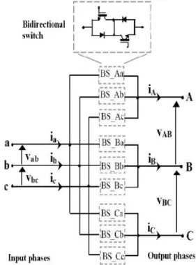
The three-phase to three-phase matrix converter consists of nine bidirectional switches that allow any output phase to be connected to any input phase. The circuit scheme is shown in Fig. 1. The input terminals of the converter are connected to a three phase voltage-fed system, usually the grid, while the output terminals are connected to a three phase current-fed system, like an induction motor might be.
With nine bidirectional switches, the matrix converter can theoretically assume 512 (29) different switching state combinations, but not all of them can be usefully employed. Regardless of the control method used, the choice of useful matrix converter switching state combinations must comply with two basic rules: Taking into account that the converter is supplied by
a voltage source and usually feeds an inductive load, the input phases should never be short circuited and the output currents should not be interrupted. From a practical point of view, these rules imply that one and only one bidirectional switch per output phase must be switched on at any instant.
Fig. 1. Three-phase to three-phase matrix converter
Under these constraints, it can be verified that in a three phase to three-phase matrix converter only 27 different switch configurations are permitted. These 27 switch configurations are listed in Table I. Each configuration is identified by a number and by a three letter code.
The three letters describe which output phase is connected to which input phase according to the schematic representation of Fig. 1. For instance, the configuration named “baa” refers to the matrix state where output phase A is connected to input phase b, output phase B is connected to input phase a and output phase C is connected to input phase a.
According to the corresponding output voltage and input current space vectors, these matrix converter configurations are classified as “active”, “zero” and “synchronous “configurations
International Journal of Science Engineering and Advance Technology,
IJSEAT, Vol 2, Issue 1, January - 2014
ISSN 2321-6905
Table I
Matrix Converters Space Vectors
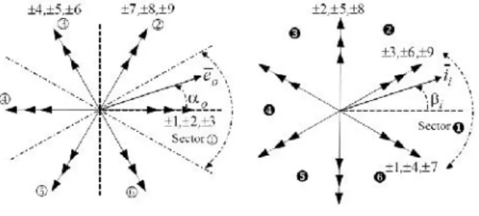
As it can be seen in the second column of Table I, the active configurations have the common feature of two output phases connected to the same input phase. There are 18 active configurations numbered by ±1,±2,…,±9 in Table I. They determine six fixed positions of the output voltage space vector which are not dependent on the input voltage space vector phase angle and six prefixed positions of the input current space vector which are not dependent on the output current space vector phase angle. The magnitude of the space vectors and is variable and depends on the instantaneous values of the input line voltages and output line currents respectively. The representation of the output voltage space vectors and input current space vectors is shown in
Fig. 2.There are 3 zero configurations which are numbered 0 in Table I. In zero configurations, the three output lines are connected to the same input phase, so that they determine zero output voltage and input current space vectors. There are 6 synchronous configurations not numbered in Table I. These configurations determine those output space vectors which have a phase angle that is dependent on the input voltage space vector phase angle. Likewise, the input current space vector has a phase angle which is related to the output current space vector phase angle. The magnitude of the space vectors and is constant and equal to the magnitude of the input phase voltage and output line current space vectors respectively.
Fig. 2. (a) Output Phase Voltage Space Vectors
(b) Input Current Space Vectors
III. PRINCIPLE OFDIRECTTORQUECONTROL BYVSI
In direct torque controlled adjustable speed drives, the motor flux and the electromagnetic torque are the reference quantities which are directly controlled by the applied inverter voltage vector. At each cycle period, the proper inverter voltage vector is selected according to the switching table given in Table II, in order to maintain the estimated torque and stator flux within the limits of two hysteresis bands. More precisely, the vector is chosen according to the position of the stator flux vector and the instantaneous errors in torque and stator flux magnitude. Looking at Fig. 3, it is worth noting that due to the fixed direction of the inverter voltage vectors and also the rotating motion of the stator flux vector in the d-q stator frame, for each inverter voltage vector, the amplitude of its radial and tangential components will be variable within a sector.
Among the 27 voltage and current vectors, only the active and null vectors will be considered in DTC. As it can be seen in Fig. 2, the direction of the active voltage vectors is constant. However, their magnitude depends on the input voltages. It should be noted that the direction of the active voltage vectors of a MC is similar to the direction of the active voltage vectors generated by a conventional VSI.
Fig. 3. VSI output line-to-neutral voltage vectors and corresponding stator flux variations
TABLEII
BASICDTCBYVSI CONFIGURATIONSELECTION
Once the classical DTC control scheme has selected the optimum vector to be applied to the machine, it is a matter of determining the corresponding matrix converter switching configuration. For example, if the VSI output vector has been chosen, looking at Table I and Fig. 2(a) and Fig. 3, it can be seen that matrix converter can generate the same vector by means of the switching configurations ±1,±2,±3. But not all of them can be usefully employed to provide vector . In fact, at any instant, the magnitude and the direction of their corresponding output voltage vectors depend on the position of the input phase voltage vector Among the 6 vectors, only those having the same direction of
and the maximum magnitude are considered. For example, looking at Fig. 4 and Table I it can be seen that, if vector is in sector 1 or 2, the switching configurations to be used are +1 and –3. It has been verified that, whatever is the sector which the vector is in, the matrix converter has always two switching configurations for each VSI output vector chosen by the classical DTC scheme. Such redundancy can be benefited to control a third variable in addition to the stator flux and the electromagnetic torque. The average value of the sine of the displacement angle ψi between the input
current vector and the corresponding input phase voltage vector has been chosen as the third variable. This variable will be indicated by sin ψi. If the
constraint to comply with is a unity input power factor, such aim can be achieved by keeping the value of sin ψiequal to zero. The variable sin ψiis
directly controlled by the hysteresis comparator. The switching table based on these principles is shown in Table III [7]. In the first column, the voltage vectors selected by the conventional DTC are present. The top row contains the sector in which the input phase voltage vector lies. Depending on whether the power factor control needs Cψ, one of the
two columns +1,-1 is selected.
TABLEIII
MATRIXCONVERTERSWITCHINGTABLE FORDTC
V. IMPROVEMENT OFDTCUSING ALLVECTORS OF
MATRIXCONVERTER
By dividing the input voltage vector path into twelve sectors, according to Fig. 4 and using the new MC switching table for DTC presented in Table IV, the DTC algorithm will be able to distinguish between small, medium and large vectors. In order to reduce the torque ripple, in addition to the large vectors of MC, the medium and small vectors can also be used. Thus the DTC scheme must be modified resulting in a new torque hysteresis comparator that will provide seven different levels instead of three levels to Among the 27 voltage and current vectors, only the
active and null vectors will be considered in DTC. As it can be seen in Fig. 2, the direction of the active voltage vectors is constant. However, their magnitude depends on the input voltages. It should be noted that the direction of the active voltage vectors of a MC is similar to the direction of the active voltage vectors generated by a conventional VSI.
Fig. 3. VSI output line-to-neutral voltage vectors and corresponding stator flux variations
TABLEII
BASICDTCBYVSI CONFIGURATIONSELECTION
Once the classical DTC control scheme has selected the optimum vector to be applied to the machine, it is a matter of determining the corresponding matrix converter switching configuration. For example, if the VSI output vector has been chosen, looking at Table I and Fig. 2(a) and Fig. 3, it can be seen that matrix converter can generate the same vector by means of the switching configurations ±1,±2,±3. But not all of them can be usefully employed to provide vector . In fact, at any instant, the magnitude and the direction of their corresponding output voltage vectors depend on the position of the input phase voltage vector Among the 6 vectors, only those having the same direction of
and the maximum magnitude are considered. For example, looking at Fig. 4 and Table I it can be seen that, if vector is in sector 1 or 2, the switching configurations to be used are +1 and –3. It has been verified that, whatever is the sector which the vector is in, the matrix converter has always two switching configurations for each VSI output vector chosen by the classical DTC scheme. Such redundancy can be benefited to control a third variable in addition to the stator flux and the electromagnetic torque. The average value of the sine of the displacement angle ψi between the input
current vector and the corresponding input phase voltage vector has been chosen as the third variable. This variable will be indicated by sin ψi. If the
constraint to comply with is a unity input power factor, such aim can be achieved by keeping the value of sin ψiequal to zero. The variable sin ψiis
directly controlled by the hysteresis comparator. The switching table based on these principles is shown in Table III [7]. In the first column, the voltage vectors selected by the conventional DTC are present. The top row contains the sector in which the input phase voltage vector lies. Depending on whether the power factor control needs Cψ, one of the
two columns +1,-1 is selected.
TABLEIII
MATRIXCONVERTERSWITCHINGTABLE FORDTC
V. IMPROVEMENT OFDTCUSING ALLVECTORS OF
MATRIXCONVERTER
International Journal of Science Engineering and Advance Technology,
IJSEAT, Vol 2, Issue 1, January - 2014
ISSN 2321-6905
distinguish between small, medium and large positive and negative torque errors. The new seven- level hysteresis comparator is shown in Fig. 5.If the ideal value of Cψfor power factor hysteresis comparator,
can’t be found in one input voltage sector, then the other vector in the same sector can be selected from Table IV to control the unit input power factor.
As it is shown in Fig. 5, when the absolute value of torqueerror ETe is equal to or greater than
0.2, and less than 0.6, the value of HTeis ±1, the small
voltage vector table is selected and ETewill decrease
until the absolute value of ETeis equal to 0.1.When
the absolute value of torque error ETeis equal to or
greater than 0.6, and less than 1, the value of HTeis
±2, the medium voltage vector table is selected and ETe will decrease until the absolute value of ETe is
equal to 0.2.When the absolute value of torque error ETeis equal or greater than 1, the value of HTeis ±3,
the large voltage vector table is selected and ETewill
decrease until the absolute value of ETe is equal to
0.6.
VI. SIMULATIONRESULTS
In order to validate the proposed method and compare it with the classical DTC using MC, some simulations have been carried out. The test machine is a standard 7.5 kW four-pole 400V 50Hz cage induction motor and has the following parameters: Rs=0.7384 Ω Rr=0.742 Ω Lm=0.1241 H
Lls=3.045 mH Llr=3.045 mH
Fig. 4. Small, medium and large voltage vectors of matrix converter and 12 sector of input line voltage
TABLEIV
LOOKUPTABLE FOR THEUSE OFALLMCVOLTAGEVECTORS
The simulation model of this novel DTC-MC adjustable speed system is set up with MATLAB/SIMULINK power system toolbox. The sampling period used is 20μs and the matrix converter model has been developed using IGBT switches.
A. High-Speed Results:
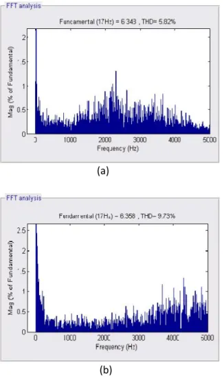
These results are obtained with both the classical method and the proposed method at speed 1000 rpm and torque 25 N.m. The electromagnetic torque, and the output current THD, are shown in Fig. 6 and Fig. 7 respectively. It can be seen that in the proposed method, torque ripple and output current THD are significantly reduced.
(a)
(b)
Fig. 6. Electromagnetic torque at 1000 rpm in
(a) Classical method (b) Proposed method
(a)
(b)
Fig. 7. Output Current THD at 6.5 N.m and 500 rpm in (a) Classical method (b) Proposed method
VIII. REFERENCES
International Journal of Science Engineering and Advance Technology,
IJSEAT, Vol 2, Issue 1, January - 2014
ISSN 2321-6905
matrix converters,” IEEE Compatibility in Power Electronics, pp. 53- 60, CPE 2005.
[4] C. Klumpner, P. Nielsen, I. Boldea, F. Blaabjerg, “New solutions for a low-cost power electronic building block for matrix converters,” IEEE Trans. on Industrial Electronics, vol. 49, no. 2, pp. 336-342, Apr. 2002.
[5] Der-Fa Chen, Chin-Wen Liao, Kai-Chao Yao, “Direct Torque Control for a Matrix Converter Based on Induction Motor Drive Systems,” IEEE Second International Conference on Innovative Computing, Information and Control, pp. 101-104, ICICIC 2007. [6] K.B. Lee, J.H. Song, I. Choy, J.Y. Yoo, “Torque Ripple Reduction in DTC of Induction Motor Driven by Three-Level Inverter With Low Switching Frequency,” IEEE Trans. on Power Electronics, vol. 17, no 2, pp 255-264, Mar. 2000.
[7] D. Casadei, G. Serra, A. Tani, “The Use of Matrix Converters in Direct Torque Control of Induction Machines,” IEEE Trans. on Industrial Electronics, vol. 48, no. 6, pp. 1057-1064, Dec. 2001.
About the authors:
1.Kanchana.Rajesh Babu, Persuing M.Tech (Power & Industrial Drives) in Nimra college of Engineering & Technology.He received his Bachelors Degree in Electrical & Electronics Engineering from Vivekanada Institute of Technology & Science,Karimnagar. his areas of interests includes power electronics & Drives
Email: [email protected]
2. Saidk Ahamad Khan working as an Assistant Professor in Electrical & Electronics Engineering at Nimra College of Engineering & Technology.He Received his Masters of Technology in Power & Industrial Drives specilization from Nimra College of Engineering & Technology,ibrahimpatnam & His Bachelors Degree in Electrical & Electronics Engineering from Chiral Engineering College,Chirala.his areas of interests includes power electronics & Drives