Managing Your Network
This chapter describes how to perform network management tasks with your ADSL2+ Modem Wireless Router.
Backing Up, Restoring, or Erasing Your Settings
The configuration settings of the modem router are stored in a configuration file in the modem router. This file can be backed up to your computer, restored, or reverted to factory default settings. The procedures below explain how to do these tasks.
Backing Up the Configuration to a File
1. Log in to the modem router at its default LAN address of http://192.168.0.1 with its default user name of admin default password of password, or using whatever user name, password and LAN address you have chosen for the modem router.
2. Under the Maintenance heading on the main menu, select Backup Settings to display the Backup Settings screen:
3. Click Backup to save a copy of the current settings. 4. Store the .cfg file on a computer on your network.
Restoring the Configuration from a File
To restore the configuration:1. Log in to the modem router at its default LAN address of http://192.168.0.1 with its default user name of admin default password of password, or using whatever user name, password and LAN address you have chosen for the modem router.
2. Under the Maintenance heading on the main menu, select Backup Settings. 3. Enter the full path to the file on your network, or click Browse to locate the file.
4. When you have located the .cfg file, click Restore to upload the file to the modem router. 5. The modem router reboots.
Erasing the Configuration
You can use the Erase feature to erase its configuration settings and restore the modem router to the factory default settings.
To erase the configuration:
1. Under the Maintenance heading on the main menu select, Backup Settings. 2. Click Erase.
3. The modem router reboots.
After an erase, the modem router password is password, the LAN IP address is 192.168.0.1, and the modem router DHCP client is enabled.
Upgrading the Modem Router Firmware
The software of the modem router is stored in flash memory, and can be upgraded as new software is released by NETGEAR. Upgrade files can be downloaded from the NETGEAR website. If the upgrade file is compressed (a .zip file), you must first extract the binary (.bin or .img) file before uploading it to the modem router.
Note: To restore the factory default configuration settings when you do not know the login password or IP address, press both the Wireless button and WPS button on the side of the modem router for 5 seconds.
NETGEAR recommends that you back up your configuration before doing a firmware upgrade. After the upgrade is complete, you might need to restore your configuration settings.
To upgrade the modem firmware:
1. Download and unzip the new software file from NETGEAR.
The Web browser used to upload new firmware into the modem router must support HTTP uploads. NETGEAR recommends using Microsoft Internet Explorer 5.0 or later, or Mozilla Firefox 2.0 or later.
2. Log in to the modem router at its default LAN address of http://192.168.0.1 with its default user name of admin default password of password, or using whatever user name, password and LAN address you have chosen for the modem router.
3. From the main menu, under the Maintenance heading, select Router Upgrade to display the Firmware Upgrade screen:
4. Click Browse to locate the binary (.bin or .img) upgrade file. 5. Click Upload.
Figure 4-2
Warning: When uploading software to the modem router, it is important not to interrupt the Web browser by closing the window, clicking a link, or loading a new page. If the browser is interrupted, it might corrupt the software, causing modem router to be unworkable and inaccessible. When the upload is complete, your modem router will automatically restart. The upgrade process typically takes about 1 minute. In some cases, you might need to clear the configuration and reconfigure the modem router after upgrading.
Network Management Information
The modem router provides a variety of status and usage information which is discussed below.
Viewing Modem Router Status and Usage Statistics
From the main menu, below the Maintenance heading, select Router Status to view this screen.
The Router Status screen provides status and usage information. This screen shows the following parameters:
Figure 4-3
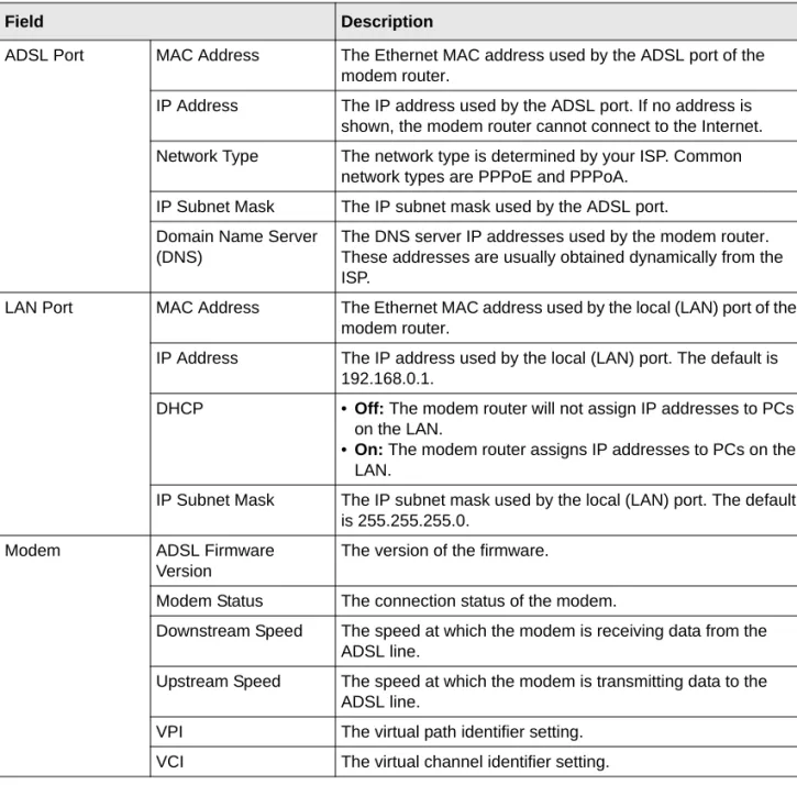
Table 4-1. Modem Router Status Fields
Field Description
Account Name The host name assigned to the modem router in the Basic Settings screen.
ADSL Port MAC Address The Ethernet MAC address used by the ADSL port of the modem router.
IP Address The IP address used by the ADSL port. If no address is shown, the modem router cannot connect to the Internet. Network Type The network type is determined by your ISP. Common
network types are PPPoE and PPPoA. IP Subnet Mask The IP subnet mask used by the ADSL port. Domain Name Server
(DNS)
The DNS server IP addresses used by the modem router. These addresses are usually obtained dynamically from the ISP.
LAN Port MAC Address The Ethernet MAC address used by the local (LAN) port of the modem router.
IP Address The IP address used by the local (LAN) port. The default is 192.168.0.1.
DHCP • Off: The modem router will not assign IP addresses to PCs on the LAN.
•On: The modem router assigns IP addresses to PCs on the LAN.
IP Subnet Mask The IP subnet mask used by the local (LAN) port. The default is 255.255.255.0.
Modem ADSL Firmware Version
The version of the firmware.
Modem Status The connection status of the modem.
Downstream Speed The speed at which the modem is receiving data from the ADSL line.
Upstream Speed The speed at which the modem is transmitting data to the ADSL line.
VPI The virtual path identifier setting. VCI The virtual channel identifier setting.
Table 4-1. Modem Router Status Fields (continued)
Viewing Statistics
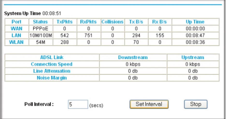
Click the Show Statistics button on the Router Status screen to display modem router usage statistics:
Wireless Port These are set in the Wireless Settings page; see
“Manually Configuring Your Wireless Settings” on page 2-7.
Name (SSID) The service set ID, also known as the wireless network name. Region The country where the unit is set up for use.
Channel The current channel, which determines the operating frequency.
Wireless AP Indicates if the access point feature is disabled or not. If not enabled, the Wireless LED on the front panel will be off. Broadcast Name Indicates if the DG834G v5 is configured to broadcast its
SSID.
Figure 4-4
Table 4-1. Modem Router Status Fields (continued)
This following table explains the statistic fields.
Viewing Connection Status
Click the Connection Status button on the Router Status screen to view the connection status:
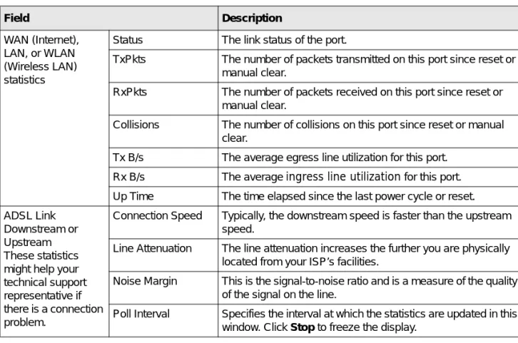
Table 4-2. Router Statistics Fields
Field Description
WAN (Internet), LAN, or WLAN (Wireless LAN) statistics
Status The link status of the port.
TxPkts The number of packets transmitted on this port since reset or manual clear.
RxPkts The number of packets received on this port since reset or manual clear.
Collisions The number of collisions on this port since reset or manual clear.
Tx B/s The average egress line utilization for this port. Rx B/s The average ingress line utilization for this port. Up Time The time elapsed since the last power cycle or reset. ADSL Link
Downstream or Upstream These statistics might help your technical support representative if there is a connection problem.
Connection Speed Typically, the downstream speed is faster than the upstream speed.
Line Attenuation The line attenuation increases the further you are physically located from your ISP’s facilities.
Noise Margin This is the signal-to-noise ratio and is a measure of the quality of the signal on the line.
Poll Interval Specifies the interval at which the statistics are updated in this window. Click Stop to freeze the display.
This screen shows the following statistics:
Viewing Attached Devices
The Attached Devices screen contains a table of all IP devices that the modem router has discovered on the local network. From the main menu, under the Maintenance heading, select Attached Devices. The Attached Devices screen displays:
For each device, the table shows the IP address, device name if available, and the Ethernet MAC address. Note that if the modem router is rebooted, the table data is lost until the modem router rediscovers the devices. To force the modem router to look for attached devices, click the Refresh button.
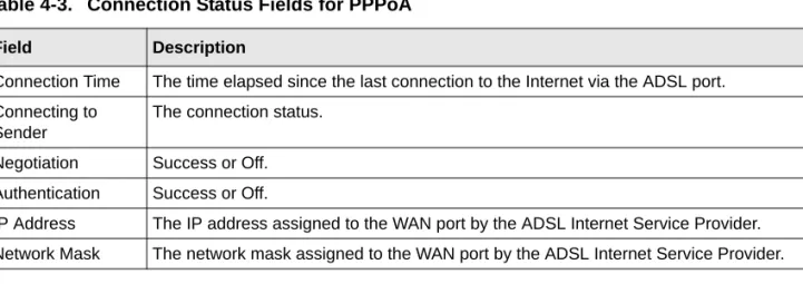
Table 4-3. Connection Status Fields for PPPoA
Field Description
Connection Time The time elapsed since the last connection to the Internet via the ADSL port. Connecting to
Sender
The connection status. Negotiation Success or Off. Authentication Success or Off.
IP Address The IP address assigned to the WAN port by the ADSL Internet Service Provider. Network Mask The network mask assigned to the WAN port by the ADSL Internet Service Provider.
Viewing, Selecting, and Saving Logged Information
The modem router logs security-related events such as denied incoming service requests, hacker probes, and administrator logins. If you enabled content filtering in the Block Sites screen, the Logs screen can show you when someone on your network tries to access a blocked site. If you enabled e-mail notification, you receive these logs in an e-mail message. If you do not have e-mail notification enabled, you can view the logs here.
An example of the logs file is shown in the following figure:
Log entries are described in the following table.
Figure 4-7
Table 4-4. Security Log Entry Descriptions
Field Description
Current time The date and time the log entry was recorded. Description or
action
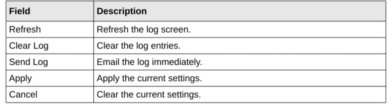
Log action buttons are described in the following table.
Selecting Which Information to Log
Besides the standard information listed previously, you can choose to log additional information. Those optional selections are as follows:
• Attempted access to blocked site
• Connections to the Web-based interface of the modem router • Modem Router operation (start up, get time, etc.)
• Known DoS attacks and port scans Saving Log Files on a Server
You can choose to write the logs to a computer running a syslog program. To activate this feature, select to the Broadcast on LAN radio button or enter the IP address of the server where the syslog file will be written.
Source IP The IP address of the initiating device for this log entry. Source port and
interface
The service port number of the initiating device, and whether it originated from the LAN or WAN.
Destination The name or IP address of the destination device or website. Destination port and
interface
The service port number of the destination device, and whether it is on the LAN or WAN.
Table 4-5. Log Action Buttons
Field Description
Refresh Refresh the log screen. Clear Log Clear the log entries. Send Log Email the log immediately. Apply Apply the current settings. Cancel Clear the current settings.
Table 4-4. Security Log Entry Descriptions
Log Message Examples
Following are examples of log messages. In all cases, the log entry shows the timestamp as: Day, Year-Month-Date Hour:Minute:Second.
Activation and Administration
Tue, 2002-05-21 18:48:39 - NETGEAR activated
[This entry indicates a power-up or reboot with initial time entry.]
Tue, 2002-05-21 18:55:00 - Administrator login successful - IP:192.168.0.2 Thu, 2002-05-21 18:56:58 - Administrator logout - IP:192.168.0.2
[This entry shows an administrator logging in and out from IP address 192.168.0.2.]
Tue, 2002-05-21 19:00:06 - Login screen timed out - IP:192.168.0.2
[This entry shows a time-out of the administrator login.]
Wed, 2002-05-22 22:00:19 - Log emailed
[This entry shows when the log was e-mailed.] Dropped Packets
Wed, 2002-05-22 07:15:15 - TCP packet dropped - Source:64.12.47.28,4787,WAN - Destination:134.177.0.11,21,LAN - [Inbound Default rule match]
Sun, 2002-05-22 12:50:33 - UDP packet dropped - Source:64.12.47.28,10714,WAN - Destination:134.177.0.11,6970,LAN - [Inbound Default rule match]
Sun, 2002-05-22 21:02:53 - ICMP packet dropped - Source:64.12.47.28,0,WAN - Destination:134.177.0.11,0,LAN - [Inbound Default rule match]
[These entries show an inbound FTP (port 21) packet, User Datagram Protocol (UDP) packet (port 6970), and Internet Control Message Protocol (ICMP) packet (port 0) being dropped as a result of the default inbound rule, which states that all inbound packets are denied.]
Enabling Security Event E-mail Notification
To receive logs and alerts by e-mail, you must provide your e-mail information in the E-mail screen:
• Turn e-mail notification on. Select this check box if you want to receive e-mail logs and alerts from the modem router.
• Send alerts and logs via email.
– Send To This E-mail Address. Enter the e-mail address where you want to send the alerts and logs. Use a full e-mail address, such as [email protected].
– Outgoing Mail Server. Enter the name or IP address of the outgoing SMTP mail server of your ISP (such as mail.myISP.com).
– My Mail Server requires authentication. Select this check box if you need to log in to your SMTP server to send E-mail. If you select this feature, you must enter the user name and password for the mail server.
Figure 4-8
Tip: If you cannot remember this information, check the settings in your e-mail program.
• Send alert immediately. Select the corresponding check box if you would like immediate notification of a significant security event, such as a known attack, port scan, or attempted access to a blocked site.
• Send logs according to this schedule. Specifies how often to send the logs: Hourly, Daily, Weekly, or When Full.
– Day for sending log. Specifies which day of the week to send the log. Relevant when the log is sent weekly.
– Time for sending log. Specifies the time of day to send the log. Relevant when the log is sent daily or weekly.
If the Weekly, Daily, or Hourly option is selected and the log fills up before the specified period, the log is automatically e-mailed to the specified e-mail address. After the log is sent, it is cleared from the modem router’s memory. If the modem router cannot e-mail the log file, the log buffer might fill up. In this case, the modem router overwrites the log and discards its contents.
Running Diagnostic Utilities and Rebooting the Modem
Router
The modem router has a diagnostics feature. You can use the Diagnostics screen to perform the following functions from the modem router:
• Ping an IP address to test connectivity to see if you can reach a remote host. If Ping VPN is enabled, the ping packet always goes through the VPN if the VPN tunnel is enabled and working.
• Perform a DNS lookup to test if an Internet name resolves to an IP address to verify that the DNS server configuration is working.
• Display the routing table to identify what other modem routers the modem router is communicating with.
• Reboot the modem router to enable new network configurations to take effect or to clear problems with the modem router’s network connection.
From the main menu, under the Maintenance heading, select Modem Router Diagnostics to display the Diagnostics screen:
Enabling Remote Management
Using the Remote Management screen, you can allow a user or users on the Internet to configure, upgrade, and check the status of your modem router.
Configuring Remote Management
1. Log in to the modem router at its default LAN address of http://192.168.0.1 with its default user name of admin default password of password, or using whatever user name, password and LAN address you have chosen for the modem router.
Figure 4-9
Tip: Be sure to change the modem router default password to a very secure password. The ideal password should contain no dictionary words from any language, and should be a mixture of letters (both upper-case and lower-case), numbers, and symbols. Your password can be up to 30 characters.
2. Under the Advanced heading of the main menu, select Remote Management to display the Remote Management screen:
3. Select the Turn Remote Management On check box.
4. Specify which external addresses will be allowed to access the modem router’s remote management.
For security, restrict access to as few external IP addresses as practical: • To allow access from any IP address on the Internet, select Everyone.
• To allow access from a range of IP addresses on the Internet, select IP address range. Enter a beginning and ending IP address to define the allowed range.
• To allow access from a single IP address on the Internet, select Only This Computer. Enter the IP address that will be allowed access.
5. Specify the port number that will be used for accessing the management interface.
Web browser access normally uses the standard HTTP service port 80. For greater security, you can change the remote management Web interface to a custom port by entering that number in the field provided. Choose a number between 1024 and 65535, but do not use the number of any common service port. The default is 8080, which is a common alternate for HTTP.
6. Click Apply to have your changes take effect.
When accessing your modem router from the Internet, you will type your modem router WAN IP address in your Internet browser address or location field, followed by a colon (:) and the custom port number. For example, if your external address is 134.177.0.123 and you use port number 8080, enter:
http://134.177.0.123:8080