Mobile Trillium Engine
Thesis report byMuhammad Ahmed Ali
SEDS 2006 - 2008Personal number: 19840405 – 5678 [email protected]
Master’s in Software Engineering of Distributed Systems
Thesis supervised by
Mihhail Matskin
Professor Royal Institute of Technology Stockholm, Sweden
And
Vincent Dollet CTO Appear Networks AB
Acknowledgements
I am grateful to Prof. Mihhail Matskin for supervising my thesis and KTH for providing a great learning opportunity. I would also like to thank Appear Networks mobile development team, platform development team, SITA engineering team and especially Mr. Vincent Dollet for his guidance, technical feedback and encouragement.
Abstract
Muhammad Ahmed Ali, Senior Software Engineer, Appear Networks AB Abstract of Master’s thesis, submitted in September 2013
Mobile trillium engine development, integration and deployment in clustered environment
“The air transport industry has a constantly growing mobile workforce and a complex, dynamic workflow that requires workers to access and act on the real time information. Rapid mobilization and automation of the key workflow process will allow air transport industry to reduce business cost, better management and improved customer services.” [1]
The aim of this thesis is to develop a backend system that integrates an existing asset, incident and change management system which is widely used in air transport industry to a mobility platform. The solution enables the field engineers to do limited incident and change management on hand held devices using a mobile application. The business data required by the mobile application is extracted from the legacy incident management system and injected into the mobility platform which makes it readily available for the mobile application. Any updates made by field engineers using the mobile application are synchronized back to the incident management system via this solution.
Table of contents ACKNOWLEDGEMENTS ... 1-2 ABSTRACT ... 1-3 1 INTRODUCTION ... 1-10 1.1 MOTIVATION ... 1-10 1.2 PROBLEM STATEMENT ... 1-10 1.3 GOAL ... 1-11 1.4 PROPOSED SOLUTION ... 1-11 1.5 REPORT STRUCTURE ... 1-12
2 PRELIMINARY STUDY AND RELATED WORK ... 2-13
2.1 APPEAR IQ MOBILITY PLATFORM ... 2-13
2.1.1 Platform components ... 2-13 2.1.2 Integration with other systems ... 2-13 2.1.3 Key features used by MTE ... 2-13
2.2 MTE DEVELOPMENT ... 2-14 2.2.1 Web services ... 2-14 2.2.2 Build tool (Apache Ant) ... 2-15 2.2.3 Google protocol buffer ... 2-16 2.2.4 SOAP UI ... 2-16 2.2.5 SVN kit library ... 2-17 2.2.6 Oracle database ... 2-18 2.2.7 JBoss application server & clustering ... 2-18 2.2.8 Spring framework ... 2-18 3 ARCHITECTURE AND DESIGN ... 3-19
3.1 INTRODUCTION ... 3-19
3.2 OVERALL SYSTEM ARCHITECTURE ... 3-19
3.2.1 Mobile layer ... 3-19 3.2.2 Middleware layer ... 3-20 3.2.3 Mobile services layer ... 3-20 3.2.4 Enterprise layer ... 3-21
3.3 OVERALL SYSTEM DESIGN ... 3-22
3.3.1 Introduction ... 3-22
3.4 MTE ARCHITECTURE AND DESIGN IN DEPTH ... 3-24
3.4.1 Major conceptual features... 3-24 3.4.2 Integration with Trillium and data extraction ... 3-24 3.4.3 Model and store the data in MTE ... 3-28 3.4.4 Integration with Mobility platform ... 3-31 3.4.5 Integration with Trillium mobile application ... 3-35 3.4.6 Use cases ... 3-36 3.4.7 Clustering support ... 3-42 4 MOBILE APPLICATION ... 4-44 4.1.1 FE authentication ... 4-44 4.1.2 View incident list and incident details ... 4-45 4.1.3 View incident details and activity logs ... 4-45 4.1.4 Create an incident ... 4-46 4.1.5 Update an incident ... 4-47 5 EVALUATION ... 5-48 5.1 STRENGTHS ... 5-48 5.1.1 Performance ... 5-48 5.1.2 Reliability ... 5-48 5.1.3 Availability ... 5-49 5.1.4 Scalability ... 5-49 5.2 LIMITATIONS ... 5-50 5.2.1 Support for new airports ... 5-50 5.2.2 Robust database initialization process ... 5-50 6 RESULTS AND FUTURE WORK ... 6-51 6.1.1 Results ... 6-51 6.1.2 Future improvements ... 6-51 7 BIBLIOGRAPHY ... 7-52
LIST OF FIGURES
Figure 2-1: Client service class generated from WSDL... 2-15 Figure 2-2: MTE Ant build script integrated in a Java IDE ... 2-16 Figure 2-3: Example address book proto ... 2-16 Figure 2-4: Trillium WSDL imported into SOAP UI ... 2-17 Figure 2-5: SVN Kit library big picture ... 2-17 Figure 3-1: Overall architectural representation ... 3-21 Figure 3-2: System design ... 3-22 Figure 3-3: Trillium web interface ... 3-22 Figure 3-4: Mobility platform admin interface ... 3-23 Figure 3-5: Login SOAP request ... 3-25 Figure 3-6: Extract data SOAP request ... 3-27 Figure 3-7: Dynamic and semi static business data model (i) ... 3-28 Figure 3-8: Static business data model (ii) ... 3-30 Figure 3-9: Synchronize datasets using continues synchronization ... 3-32 Figure 3-10: HTTP forwarding configuration ... 3-32 Figure 3-11: Http forwarding mapping ... 3-33 Figure 3-12: Dynamic data sync via HTTP forwarding ... 3-33 Figure 3-13: Updates via messaging ... 3-34 Figure 3-14: Message receiver configuration ... 3-34 Figure 3-15: Static data proto schema ... 3-35 Figure 3-16: Use case diagram ... 3-36 Figure 3-17: FE authentication use case ... 3-37 Figure 3-18: Update incident use case ... 3-39 Figure 3-19: Create incident user case ... 3-40
LIST OF TABLES
Table 3-1: Login SOAP request ... 3-25 Table 3-2: Extract data SOAP request ... 3-27 Table 3-3: Incident entity ... 3-29 Table 3-4: Activity logs entity ... 3-29 Table 3-5: Group Member entity... 3-30 Table 3-6: ServiceCI entity ... 3-30 Table 3-7: Priority entity ... 3-31 Table 3-8: Reporting method entity ... 3-31 Table 3-9: Create incident SOAP request ... 3-42
Glossary
AIQ Appear networks mobility platform ATI Air transport industry
MTE Mobile trillium engine
ITSM Information technology service management SITA MMS SITA mobile middleware solution
HHT Handheld terminal, mobile devices
1
Introduction
1.1
Motivation
SITA1 is the world leading specialist in air transport communication and information technology [2] and Appear Networks2 provide end to end mobility solutions for enterprise [3]. AIQ mobility platform is offered by SITA as a hosted service (SITA MMS) and can reach 250 airports around the globe where SITA infrastructure already exists.
“The air transport industry has a constantly growing mobile workforce and a complex, dynamic workflow model, requiring workers to access and act on real-time information. In today’s environment, however, many processes on the ground are still static, paper-based and nothing like as efficient as they could be – since they are unable to leverage the power of the information locked in ATI applications and systems.
The answer is a mobile workforce solution that can deliver the right information at the right time to mobile field workers – using applications which can anticipate their needs and requirements based on a number of context parameters (location, time, staff certification, network-type, etc.)” [4].
1.2
Problem statement
In today’s world a small airport can hold hundreds of assets (check-in terminals, boarding card printers, computers etc.) and on a larger airport this number can easily reach thousands. SITA is a leading provider of these assets and provide active support to customers (mainly airlines using these assets), to meet the customer service level agreements its critical to have a system to keep track of all the assets, raise a ticket/incident if something goes wrong and assign it to the right field engineer who can resolve the issue.
Unicenter Service Desk3 product allows incident, knowledge and change management [5], SITA has customized and adapted this product for air transport industry and this SITA system is named Trillium which allows SITA personnel (e.g. field engineers, service desk staff) working on airports to perform asset, incident and change management.
Trillium is a legacy web application with a complex web interface on the other hand FE’s are moving around in the airport and needs instant information on finger tips in addition FE’s are only interested in the information required to identify an asset and resolve the ticket which means a traditional backend system that requires a workstation is really not usable that is the reason why SITA wants to mobilize this ITSM thus enabling its field engineers to interact with Trillium system and carry on limited incident management activities using a mobile application. 1http://www.sita.aero 2 http://www.appearnetworks.com/ 3 http://www.ca.com/us/service-desk-software.aspx
1.3
Goal
To do incident management using a mobile application the mobile application needs to be integrated with the Trillium backend system. Considering the number of airports, the number of field engineers, the firewall issues and huge volume of data involved it is not feasible for this mobile application to talk directly to Trillium backend system a mobile device has limited resources (i.e. memory, computing power, network, battery) which means it can server as a user interface to the system but not an integration endpoint to the system.
In addition, to manage the life cycle of a mobile application (i.e. install, upgrade and data synchronization) and to make sure that the device only gets the minimum user specific data a mobile application platform is required which provide the application management features and continues data synchronization.
The goal of this thesis is to develop a backend system named Mobile Trillium Engine (MTE) that integrates this mobile application platform to Trillium system. This means there is only single point of contact for the Trillium system.
MTE extracts the required business data from Trillium and injects it to the AIQ mobility platform. Mobility platform then synchronize this data to the mobile devices and makes it available for the mobile application. Any updates made by the user using the mobile application are synchronized back via AIQ to MTE and then all the way to Trillium thus enabling the field engineers located at airports to access Trillium using personal hand held devices over cellular or WiFi networks.
Another challenge is the huge volume of data for different airports that is stored in the Trillium system and as MTE needs to extract it thus a data extraction mechanism needs to be developed that extract only the required subset of this data and always do incremental check for updates on this data.
1.4
Proposed solution
The Trillium system exposes web services to integrate external systems. A thick backend application MTE is developed that is integrated to Trillium using web services and has following major features
Extract large volumes of business data from Trillium system and store it locally in a database
Inject data to the AIQ mobility platform that synchronize it to the mobile devices
Expose web services to receive updates from AIQ mobility platform sent by mobile application and forward these updates to the Trillium system
Look for new available data on Trillium at schedules intervals and synchronize as soon as its available
Is scalable reliable and robust to handle large volumes of data and serve large number of users.
1.5
Report structure
This thesis report is divided into 7 chapters. Chapter 1 mainly focuses on introduction to problem and defines the goals for this thesis. In chapter 2 the initial study conducted and selection of software and technologies is explained. In chapter 3 overall system design and architecture is discussed. In chapter 4 the mobile trillium application is explained. In chapter 5 we evaluate the solution and approach towards problem solution. In final chapter number 6 we focus on the results and future improvements and chapter number 7 include the list of references.
2
Preliminary study and related work
To achieve the goals given in section 1.3 and to develop a backend application that bridges the Trillium system to AIQ mobility platform different existing tools and protocols are used which are explained in this section.
2.1
Appear IQ mobility platform
“Appear IQ mobility platform enables you to manage the entire lifecycle of mobile application deployment: from user management through to application distribution, troubleshooting, data synchronization and reporting. You can deploy and manage your own mobile enterprise applications.” [3]
2.1.1 Platform components
“AIQ architecture is modular and separates the system responsibilities into distinct components: back-end servers, one or more local network proxies and client software installed in the end-user devices”. [6]
Appear IQ mobility platform has following major components:
1. AIQ administration server “is considered to be a component that is used by administrators to perform administrative tasks. The AIQ administration interface is a web based user interface. Admin server is used to configure AIQ modules. After the configurations are saved, administration server notifies currently connected AIQ proxies about configuration changes, so they can re-configure themselves to use new configurations”. [6]
2. AIQ proxy “component interacts with AIQ clients. It retrieves configurations configured by administrators from AIQ administration server and re-configures itself. It is the proxy responsibility to distribute all the required resources to clients and keep the data in sync. Proxies can be looked upon as more local components located near to end users, several proxies connecting to one central administration server”. [6]
3. AIQ message/integration server “provides the functionality to inject arbitrary messages into the system that will be delivered to clients. It is a core component for sending reliable messaging”. [6]
4. AIQ client “is an endpoint that an end-user can interact with AIQ system. It provides graphical user interfaces and can communicate with AIQ proxy by sending messages that comply to AIQ protocols”. [6]
2.1.2 Integration with other systems
AIQ mobility platform can be integrated with any other third party system by writing a custom integration layer. This integration layer can extract data from and inject data to the mobility platform. For example MTE is a custom integration layer that bridges the mobility platform to the Trillium system.
2.1.3 Key features used by MTE
1. Continuous data synchronization the mobility platform can transparently keep the data on the mobile handhelds in synchronization with a central subversion4 repository [7]. MTE can publish updated data into a central repository. As soon as new data is published, all impacted proxies retrieve the updated data, and publish it silently to the mobile handhelds. Integration layer (MTE) will maintain an extract of Trillium database sufficient for the mobile users, for the different airports where the service will be available. Proxies serving specific airports will automatically retrieve updated data for these airports as soon as it changes.
2. Messaging the mobility platform provides reliable messaging capabilities and any updates between backend and mobile application are exchanges using messaging.
2.2
MTE development
MTE is a scalable and fault tolerant custom web application that offers Trillium services to the mobile workforce it is Java EE application integrated with 7th generation of Appear IQ mobility platform version AIQ 7.0.
Following protocols and technologies have been used for MTE development, integration and deployment.
2.2.1 Web services
Web services SOAP7 and REST5 enable communication between applications using the standard HTTP and HTTPS protocols over the internet.
“SOAP is more focused on exposing the named operations or business logic whereas REST is more focused on exposing the resources and performing CRUD6 operations on those resources”. [8]
Trillium system exposes SOAP web services7 and MTE integrates to Trillium using this SOAP interface. Trillium provides a WSDL (web service description language) document. In MTE Java source code is generated from this WSDL document using Apache CXF8. The generated code includes client service classes that are used to call the available web service methods. The generated code is packaged to a jar file and included in MTE as a dependency. For example following is the client web service class in MTE and allowed operations. 4 http://subversion.apache.org/ 5 http://en.wikipedia.org/wiki/Representational_state_transfer 6 http://en.wikipedia.org/wiki/Create,_read,_update_and_delete 7 http://en.wikipedia.org/wiki/SOAP 8 http://cxf.apache.org/
Figure 2-1: Client service class generated from WSDL
AIQ mobility platform exposes REST web services9 and MTE integrates to mobility platform using this REST interface.
For example following is a REST web service expose for injecting messages into the mobility platform this web service exposes the message resource and allows HTTP CRUD operations
http://localhost/integration-server/public/default/messages
– HTTP GET on /integration-server/public/default/messages list all the messages
– HTTP GET on /integration-server/public/default/messages/{messageId} list a single message with a specific message id.
– HTTP POST /integration-server/public/default/messages with message XML document creates a new message
– HTTP DELTE /integration-server/public/default/messages/{messageId} deletes a message with a specific message id.
MTE itself exposes some REST web services that are used by the mobile application to extract data and inject updates.
2.2.2 Build tool (Apache Ant)
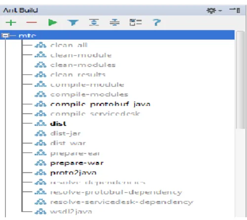
MTE is a Java EE application that involves various build steps (e.g. compile, wsdl2java, package war, package ear, ptoto2java, copy dependencies) and Apache Ant10 is used as the build tool. [9]
The build steps are written in an xml build script file, modern Java IDE (e.g. Eclipse, IntelliJ Idea) auto detects an ant build script in a Java project.
9
http://en.wikipedia.org/wiki/Representational_state_transfer
Figure 2-2: MTE Ant build script integrated in a Java IDE
The build script can be run from the command line or from within the Java IDE.
2.2.3 Google protocol buffer
Google protocol buffer11 is a very flexible, simple and efficient protocol to transfer data when compared to XML and JSON. The data contract is written in a simple .proto text file and then a utility program can be used to generate source code (Java, C#, C++). [10]
Following is a sample proto for an address book class taken from [10]
Figure 2-3: Example address book proto
The proto files serve as the data contract between MTE written in Java and the Mobile application written in C#. The REST services exposed by MTE accept and returns the data in Google protocol buffer format.
2.2.4 SOAP UI
SOAP UI12 is an open source tool very popular among the developer community to test the SOAP web services. During the MTE development SOAP UI software is used extensively to test the complex SOAP queries before doing any actual implementation.
For example following is a SOAP UI project after importing the Trillium WSDL it list all the available methods and we can test the web service calls by filling in the method parameters in request xml. The server response when this request is sent is displayed as raw xml. Following screenshot is taken from [11]
Figure 2-4: Trillium WSDL imported into SOAP UI
2.2.5 SVN kit library
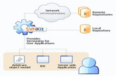
SVN kit13 library provide API for java applications to work with the subversion. By using this library java application can connect to a subversion server and can perform all the functinality that is normaly provided by a subversion client. For explanation please see the picture below taken from [12]
Figure 2-5: SVN Kit library big picture
To achieve continues data synchronization MTE and mobility platform uses SVN kit library extensively. The data that needs to be synchronized to devices is written by MTE to binary protocol buffer files and is committed to a central subversion repository. AIQ checks out a working copy of this repository and synchronize data to the device.
12
http://www.soapui.org/
2.2.6 Oracle database
Oracle database14 is an industry standard for scalable and robust applications. MTE supports oracle 10g database.
The data extracted from Trillium by MTE is stored in the database. MTE uses oracle database driver to communicate with the database. The database connection configurations are configured in the web application server as a data source file and retrieved by MTE using JNDI15. [13]
Database creation scripts are provided with MTE installation package to create database.
2.2.7 JBoss application server & clustering
MTE is a Java enterprise (J2EE) web application and requires a web container that supports EJB16. JBoss17 is an open source web application server that has full clustering support and features like automatic node discovery that require very little configuration effort. JBoss enterprise application server provides all means to develop large, scalable and robust applications. [14]
MTE is deployed in JBoss 5 application server.
2.2.8 Spring framework
MTE is a spring framework18 based web application. The spring framework in MTE is used mainly for dependency injection19 in addition the powerful abstraction provided by spring framework in form of templates for database access is extensively used.
Spring security is used to protect the web services with simple web authentication and Spring MVC is used to develop the REST web services.
14 http://en.wikipedia.org/wiki/Oracle_Database 15 http://en.wikipedia.org/wiki/Java_Naming_and_Directory_Interface 16 http://en.wikipedia.org/wiki/Enterprise_JavaBeans 17 http://www.jboss.org 18 http://www.springsource.org/spring-framework 19 http://en.wikipedia.org/wiki/Dependency_injection
3
Architecture and design
3.1
Introduction
The software architecture of the Mobile Trillium solution is based on SITA MMS platform. The focus is set on enhancing mobile experience while optimizing infrastructure costs.
Given the nature of the operations, it is designed to be highly available and scalable to support ever growing business.
3.2
Overall system architecture
This section describes the proposed software architecture of the system and explains how the mobile application, mobility platform, MTE and Trillium backend work together and are integrated.
In section 1.3 and section 1.4 the approach to solve the problem (given in section 1.2) is explained briefly. To achieve the goals and build a system on top of this approach the overall system can be divided in to four layers.
3.2.1 Mobile layer
This layer consists of components running on mobile device. These components mainly include
– Trillium mobile application which provides the user interface for the FE to do incident and change management activities
– The AIQ client provided by mobility platform this is mainly a container application and provide essential infrastructure i.e.
– connection management when the FE starts the AIQ client the connection management starts and establishes a connection to the mobility platform backend – authentication to access the trillium mobile application FE needs to authenticate
with a username and password after successful connection to the mobility platform backend the authentication process starts and FE is prompted for the credentials the provided username and password are sent to the mobility platform backend for authorization
– synchronization of business data starts after the successful authentication and data is downloaded by the client and written to the file system on the mobile device – services container the Trillium mobile application executable are downloaded by
the mobility client and presented to the FE as a service/application icon from where the FE can start the mobile Trillium application and do the incident and change management activities
– integration end points when FE makes any updates using the Trillium mobile application these updates are submitted to the mobility client which forwards it to the mobility platform backend that forwards it to MTE and from there they are sent to the Trillium backend
3.2.2 Middleware layer
This layer (AIQ mobility platform backend) provides the foundations to the mobile solution the core components explained briefly in section 2.1 include
– Administration server is the administration interface for administrators and can be considered as the configuration store [6]. The configurations are stored in a database. Proxy components connect to the administration server to download the following configurations
– Authentication configurations the configurations to connect to LDAP and authenticate based on username and password and extract the FE profile (e.g. name, email, phone number) from LDAP
– Provisioning configurations uploaded Trillium mobile application executable and other resources for example the name of the application, icons for the application – Device management configurations the AIQ client installed on FE device can be
upgraded centrally and the new AIQ client package can be uploaded to the administration server
– Synchronization configurations the URL and connection configurations of the central SVN repository server where datasets (data required by the Trillium mobile application and committed by the MTE) is located
– Message server configurations the message or integration server configurations where proxy needs to look for the messages and message routing configurations (i.e. a key value pair which says message received with a header value INCIDENT_UPDATE should be routed to a REST end point on MTE e.g. /mte/api/incidentupdate)
– Integration or messaging server is the component that stores all the messages and expose REST interface for operations on the messages [6]. The messages are stored in the database. Proxy component retrieve the messages for a client using this interface and external systems e.g. MTE submit/inject messages into the system using this interface – Proxy is the component where the configurations made in administration server is
executed, on startup the proxy connects to the AIQ administration server and downloads all the configurations given above. The AIQ client only talks to the proxy component which is a single point of contact in the system for the client from where client can
– authenticate by using the authentication configurations for LDAP the FE request to authenticate is processed
– download application/service by using the provisioning configurations the application for FE (e.g. Trillium mobile application executable) is downloaded by the client
– synchronize data by using the sync configurations the datasets (data required by Trillium mobile application) are downloaded by the client
– retrieve and submit messages by using the message server configurations the messages are retrieved by the client and updates are sent to MTE using the message routing configurations
3.2.3 Mobile services layer
This layer (MTE) mobilizes the Trillium system. It abstracts Trillium by presenting a mobile-friendly REST API for Trillium mobile application. It is in charge of extracting data from Trillium and stores it in a database and transforming complex business data into data easily use-able by the mobile application. It is also responsible for converting light mobile data into
Trillium's complex format (e.g. an incident update made by an FE when received from mobile application on MTE needs to be enriched with some more business data that is only available on or calculated by the MTE backend without this data Trillium system might reject this update.)
This layer bridges the mobility platform and the trillium backend system. It exposes the web services for clients to extract data a request to fetch a list of FE incidents arrives at Proxy which forwards this request to MTE and the response (i.e. list of incidents) is returned back to the client. The advantage to proxy these requests via AIQ proxy is that on one component i.e. AIQ proxy is open to the mobile application over internet.
If new data is available or an error report (e.g. failed incident update) is required to be sent to the mobile application then MTE injects this to the AIQ integration/message server as a message.
As there are large number of FE’s using application on many airports a heavy load is expected on the MTE so it is load balanced and a cluster of MTE servers is available to serve the mobile application requests.
3.2.4 Enterprise layer
This is where the existing legacy or conventional systems are located namely the Trillium and SITA Domain Controller (LDAP).
The Trillium system exposes web services and MTE integrates it to the mobile application. LDAP is used by mobility platform for user authentication. Users (FE’s) are created by SITA administrators in the LDAP and FE’s uses these credentials to authenticate on the AIQ client. Following is an overall representation of the system architecture explained above; the figure is taken as is from [15]
3.3
Overall system design
3.3.1 Introduction
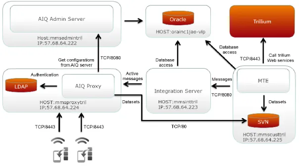
The AIQ mobility platform, MTE and Trillium are deployed in SITA datacenter managed by the SITA engineering teams. Field engineers are mobile users and they use the mobile application at different airport over 3G and wifi networks.
Following diagram explains the high level system design which is explained below
Figure 3-2: System design
The Trillium system is provided by SITA which stores all the business data (e.g. assets, incidents, incident update logs) in an oracle database it has a web interface for service desk supervisors to do knowledge management (i.e. add remove assets) and do incident/ticket management. It also provides the SOAP interface for integration with external systems and all operations (i.e. data extraction, incident management) can be performed via the SOAP interface.
Following is the web interface of Trillium system available for administrators, the screenshot is taken from [16]
The Mobile trillium engine (MTE) integrates Trillium and mobility platform. It is deployed on a dedicated web server. MTE communicates to Trillium using SOAP client. It extracts business data and incidents from Trillium and stores it locally in the database. It writes data to the SVN repository which is synchronized to mobile devices via the platform continues synchronization feature. The updates made by FE using mobile application are sent to Trillium. MTE inject messages to integration server if new data is available for mobile application or any update made by an FE is rejected by Trillium.
MTE constantly write errors to log files (e.g. failure to send updates to trillium, failed sync with trillium) this may interrupt daily operations and engineers frequently monitor these log files to address any issues.
The domain controller LDAP is provided by SITA here FE users along with credentials and user profile are created. FE’s are informed about their credentials and they use these credentials to login into the mobility platform. Mobility platform authenticates FE’s against this LDAP.
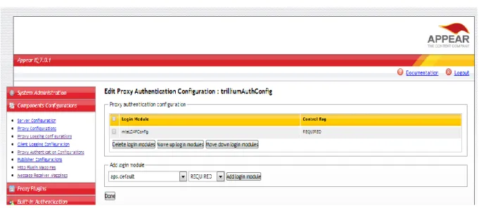
The Mobility platform include Administration server which has a web interface used by operation engineers to configure the system. The configurations are stored in the database and are fetched by the Proxy and Message server component. Proxy components periodically checks the SVN repository for any updates and if any updates are detected the data is downloaded by the clients. All the mobility platform components expose REST interfaces for communication and each mobility platform component is deployed on a dedicated web server. [6]
Following is the web interface of administration server available for administrators; the screenshot is taken from [17]
Figure 3-4: Mobility platform admin interface
FE uses the AIQ client mobile application to login and to access the mobile trillium application and do incident management. The AIQ client only talks to the AIQ proxy and all the communication to external systems e.g. MTE is done through proxy.
Following is the AIQ client application used by FE to login and start the mobile trillium application after successful authentication. The screenshots below are taken from [18]
The mobile application is explained in detail in section 4
3.4
MTE architecture and design in depth
The overall system architecture and design is explained above, the goal of this thesis as mentioned in section 1.3 and 1.4 is MTE development and in this section we focus on MTE architecture and design.
3.4.1 Major conceptual features
Following is a list of major features or use cases that have been developed in MTE to achieve the thesis goals
1. Integration with Trillium system using web services and extract the required business data and do continues synchronization for the updates on business data
2. Model and store the data locally in MTE
3. Integration with AIQ mobility platform and Trillium mobile application and serve data in a mobile application friendly format
4. Handle incident updates sent from the Mobile trillium application via AIQ mobility platform and send them over to Trillium system
The three major features given above are explained in detail in the following section.
3.4.2 Integration with Trillium and data extraction
The Trillium system in the Enterprise tier holds master data required by the Trillium mobile application. To provide a mobile solution of the Trillium system, the Mobile Trillium Engine extracts a subset of key Trillium data, relevant for mobile users such as assets and contacts to its local data storage. The engine also replicates incidents to the local data storage to improve response time to requests from handhelds. Only the attributes that are relevant to the mobile users are extracted.
3.4.2.1 Trillium business data
Trillium business data refers to data required or created when field engineers use the Trillium mobile application. This data mainly consists of
1. Global data (static & semi-static data) or common data required by all users and data which is shared by all users working in the same airports (e.g. system wide codes priority flag, cause codes, resolution codes etc). Static data (e.g. assets, contacts, contact groups information) is the data which hardly ever changes and volume of static data is small. Semi-static data is the data which does not change often during a given 8hrs window. Semi-static data is large in volume.
2. Dynamic data which is specific to individuals (e.g. incident, activity logs). This is the data which changes often during a given 8hrs window. Dynamic data is large in volume. 3.4.2.2 Trillium web service authentication
MTE integrates with Trillium system using SOAP web services. Trillium requires all web service call to be authenticated which means to extract data first MTE should login into Trillium system and gets a session id. MTE on startup starts a session manager that handles the authentication process with Trillium.
For example following is a sample SOAP request used by MTE to login [19]
Figure 3-5: Login SOAP request
Following are details of above given login SOAP request Web service method
Name loginServiceManaged
Parameters
Name Type Value
Policy String Name of the policy or login name
encrypted_policy String Encrypted policy string, base 64 encoded password string
Trillium system returns a session id if the credentials are valid. This session id has a inactivity timeout configured to 60 minutes on Trillium. The session id is store by MTE in memory and later used in all web service calls made by MTE.
On successful authentication MTE starts a scheduled service that run every 15 minutes to query session status, so that it doesn’t expire due to inactivity and incase it is expired make a new login request and get a new session.
3.4.2.3 Data extraction
After successful authentication with Trillium system MTE triggers the data extraction process. The data extraction process can be divided into two major phases.
1. Database initialization phase
2. Continues data synchronization phase
Following is the detail explanation of the above given data extraction phases.
- Database initialization phase
The database initialization phase is run only once when the MTE is run for the first time and not data has been synchronized with Trillium yet. The database schema is created using a SQL script bundled with the MTE distribution.
The database initialization phase can be further divided into following three sub phases:
- Static and semi-static data initialization phase Static and semi-static data are defined in section 3.4.2.1
To extract data MTE calls the Trillium web service multiple times with parameters that include type of data requested (e.g. priority, cause code, assets, contacts), the requested attributes of that object and where clause with incremental minimum and maximum last modified dates.
Each call requests for an amount of data in one month period. The start minimum last modified date is default to January 1st, 1990 00:00:00 UTC. This phase will stops when the maximum last modified date has passed today’s midnight in the MTE server.
- Dynamic data initialization phase Dynamic data is defined in section 3.4.2.1
The MTE calls web service with parameters that include type of data request (e.g. incidents, activity logs), the attributes required and a where clause containing a minimum last modified data and a maximum last modified date, as shown in the table below, to extract relevant business data.
The MTE calls web service multiple times with incremental minimum and maximum last modified dates. Each call requests for an amount of data in one day period. The start
minimum last modified date is default to January 1st, 2007 00:00:00 UTC. This phase stops when the maximum last modified date has passed today’s midnight in the MTE server.
When the database initialization is done, the MTE updates a database initialization fag in the database to true. This prevents the database initialization process to be executed when starting the MTE next time.
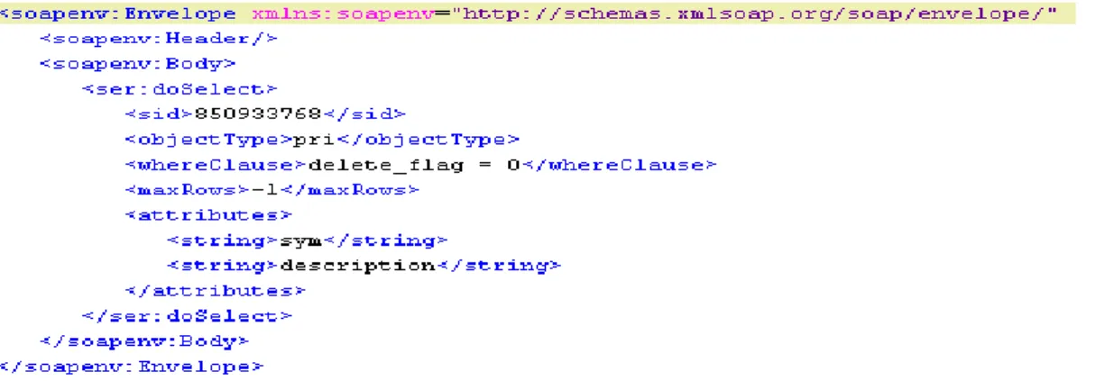
Following is a SOAP request from [19] to extract priority data from Trillium
Figure 3-6: Extract data SOAP request Web service method
Name doSelect
Parameters
Name Type Value
Sid Number Session id retrieved from the login request
Object type String Data to query (e.g. priority, assets, incidents) Where clause String Condition to filter the query data (e.g.
delete_flag=0 will give all data where delete flag is not true)
(last_modified_date > timestamp1 AND last_modified_date < timestamp2) will return data between timestamp1 and timestamp2. Similar to an SQL query where clause
Attributes Array of
String
The attributes to query for a data only these attributes will be returned in the result. If left empty all attributes will be returned, same as a select * from a table SQL query. Number of rows Number Total number of records to return (e.g. -1
means all, 1 means only one record)
- Continues data synchronization phase
Once the database init is successful MTE starts the periodic data extractors which periodically sends requests to Trillium to ask for updates on each business object type using conditions. Requests are sent every four hours, one hour and one minute for each static data object type, semi static data object type and dynamic data object type, respectively.
A condition that filters data on the last modified date field, is constructed programmatically and dynamically. The MTE reads the maximum last modified date of each business object type from the database table. In other words, when the MTE starts synchronization, it only asks for data that have changed since the last synchronization.
The synchronization process consists of:
- Insert new data into database
- Update existing data in database
- Remove data from tables if the master data have been deleted (delete_flag = 1), become invisible (zvisible = 0) or become inactive (active = 0)
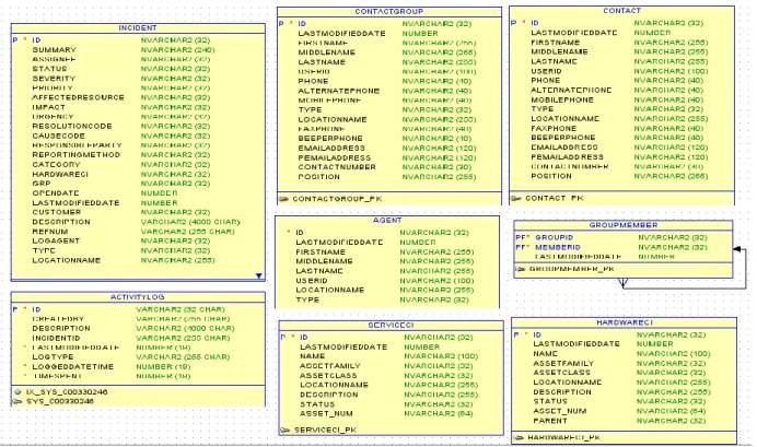
3.4.3 Model and store the data in MTE
The subset of Trillium data extracted by MTE 3.4.2 is modeled into entity classes. The Diagram below shows structure of static, semi-static and dynamic business data in MTE database. The foreign keys are used between tables but there are no constraints (e.g. delete constraints) as data e.g. the incidents should never be removed from the database. In Trillium data is never removed from the system it can become inactive.
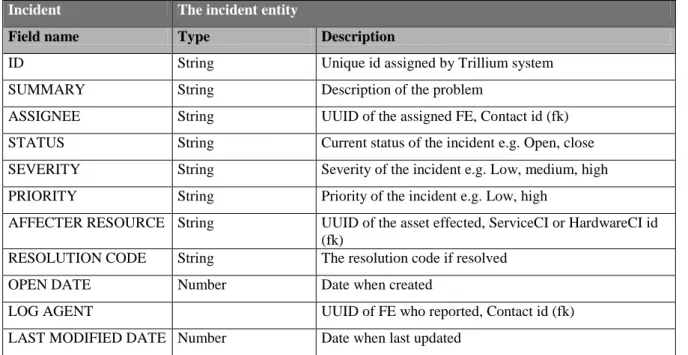
Following is the description of incident entity
Incident The incident entity
Field name Type Description
ID String Unique id assigned by Trillium system
SUMMARY String Description of the problem
ASSIGNEE String UUID of the assigned FE, Contact id (fk)
STATUS String Current status of the incident e.g. Open, close
SEVERITY String Severity of the incident e.g. Low, medium, high
PRIORITY String Priority of the incident e.g. Low, high
AFFECTER RESOURCE String UUID of the asset effected, ServiceCI or HardwareCI id
(fk)
RESOLUTION CODE String The resolution code if resolved
OPEN DATE Number Date when created
LOG AGENT UUID of FE who reported, Contact id (fk)
LAST MODIFIED DATE Number Date when last updated
Table 3-3: Incident entity
Following is the description of Activity logs of an incident
Activity log Log of any changes or updates (changed status, added comment, updated description) made to an incident
Field name Type Description
ID String Unique id assigned by Trillium system
CREATED BY String The FE, or the log agent
INCIDENT ID String Incident id for which the log is created
LAST MODIFIED DATE Number Last update data time of this log entry
LOG TYPE String Type of the log (Creation, update, status changed)
LOG DATE TIME Number Log create data time
Table 3-4: Activity logs entity
Following is the description of Group member entity, the FE (a contact) and customers are divided into groups and one customer (a contact) or FE (a contact) can belong to multiple groups
Group member Entity links the contacts and the group they belong to , a contact can belong to more than one group
Field name Type Description
GROUP ID String Group id (fk)
Table 3-5: Group Member entity
The asset is identified by two entities the HardwareCI and the ServiceCI, several HarwareCI’s can belong to one parent ServiceCI asset e.g. a boarding pass printer terminal as a whole is can be considered as ServiceCI but its components e.g. input, printer as HardwareCI’s that belong to one parent ServiceCI.
ServiceCI Service CI represents an asset
Field name Type Description
ID String UUID assigned by Trillium system
NAME String Name of the asset
ASSET FAMILY String Family of the asset (fk) to Asset Family static data
ASSET CLASS String Class of asset (fk) to Asset Class static data
LOCATION NAME String The location of asset, which airport
DESCRIPTION String The description of the asset
STATUS String The current status of the asset
Table 3-6: ServiceCI entity
HarwareCI has the same fields as ServiceCI with an extra parent filed which is a ServiceCI id. The diagram below shows the database model for static data taken from [19].
Figure 3-8: Static business data model (ii)
Following is description of the priority static data entity and Reporting method rest of static data entities has similar fields.
Field name Type Description
ID String Unique id assigned by Trillium system
DESCRIPTION String Name or description e.g. High
SYM String Numeric value e.g. 5201
LAST MODIFIED DATE Number Last updated time stamp
Table 3-7: Priority entity
Following is the description of reporting method data entity
Reporting method The method or means of reporting incident e.g. mobile app, service desk
Field name Type Description
ID String Unique id assigned by Trillium system
SYM String Numeric value e.g. Mobility
LAST MODIFIED DATE Number Last updated time stamp
Table 3-8: Reporting method entity
3.4.4 Integration with Mobility platform
As given in section 3.2 MTE integrates the AIQ mobility platform to the Trillium system. The business data extracted by MTE section 3.4.2 is converted to a mobile application friendly format and injected into the mobility platform.
3.4.4.1 Data synchronization
The MTE use continues synchronization feature explained in section 2.1.3. A central subversion repository is provided and both Mobility platform and MTE are configured with the URL to this subversion repository. Any data committed to this repository by MTE is synchronized to the Trillium mobile application.
Figure 3-9: Synchronize datasets using continues synchronization
After successful completion of database initialization phase section 3.4.2.3 MTE check out a working copy of dataset from the subversion repository. The static and semi-static data is written into the protocol buffer files and committed to the central subversion repository. AIQ proxy detects the changes in the working copy and synchronizes the updates to the AIQ client. AIQ client saves the data set files to the mobile file system. The trillium mobile application can now read these files and have access to the Trillium business data.
The dynamic data changes very often and is extracted by mobile application via direct HTTP calls. MTE exposes some REST web services to expose the dynamic data. These web services are never accessed directly by the mobile application but via HTTP request forwarding feature of the mobility platform (the request is send to an endpoint on AIQ proxy which dispatches it to a configured MTE URL).
Following is the HTTP forwarding configuration configured on the AIQ administration server, the screenshot is taken from [17]
Figure 3-10: HTTP forwarding configuration
Figure 3-11: Http forwarding mapping
A pattern is configured which means all forwarding requests from the client having pattern “trillium/{URL}/” will be forwarded to the above configured URL.
For example, if the client sends a request to
http://sita.proxy.aero/proxy/plugin/trillium/api/incidents the HTTP forward plugin will forward this request to http://mte.server.aero:8080/trillium-webapp/api/incidents
Figure 3-12: Dynamic data sync via HTTP forwarding
MTE on receiving the request reads required data from the database and sends back the response containing data in compressed protocol buffer format. This data is returned to the mobile application which processes the data and presents it to the user.
3.4.4.2 Receive updates from the mobile application
FE using the mobile application can do various updates e.g. create new incidents, update an existing incident. The mobile application uses the reliable messages described in section 5.1.2.
Figure 3-13: Updates via messaging
As illustrated in the above diagram Mobile application submits update messages to the AIQ client and the client will send messages to the AIQ Proxy.
On Proxy a message receiver is configured, proxy on receiving the messages from client it will Post the message to the configured external message receiver URL (MTE REST web service in this case). Following screenshot is taken from [17]
Figure 3-14: Message receiver configuration
The accepted code in above is the HTTP codes that are considered as success it means once the proxy get once of the success code it will not retry.
The unaccepted code in the above diagram is the HHTP codes that are considered as error codes and on receiving this error code proxy keeps on retrying the message unless it gets a success response code.
Once MTE receives the update message it checks if it is an incident create request, or an incident update request. This is specified by the mobile application by setting a HTTP header. MTE validates the request and enriches it if required with business data and send it using the SOAP client to the Trillium system.
3.4.5 Integration with Trillium mobile application
Trillium mobile application is used by the FE to view list of incidents and do incident management. The Mobile application is integrated to MTE via the mobility platform the application consumes the business data extracted by MTE from the Trillium system.
3.4.5.1 Data contract
Trillium mobile application requires the data to be in protocol buffer format. Both MTE and mobile application uses Google protocol buffer (explained in section 2.2.3) schema as the data contract.
For example following is a sample protocol buffer schema used by MTE and mobile application for static data [19]
Figure 3-15: Static data proto schema
When source code is generated from this protocol buffer schema it generates an AssetClassList class that holds a list of type static data. The static data type has three fields
- Id (is required and can’t be null)
- Name (is optional and can be null)
- Description (is optional and can be null)
The protocol buffer data files are read from the file system as stream and then un-marshaled into protocol buffer objects. For example to get a list of all AssetClass mobile application will read the assetClass.proto file downloaded via continues synchronization and un-marshal it to C# AssetClassList object. In case the any of the required field is missing the marshaling process will fail and throw an exception.
3.4.6 Use cases
3.4.6.1 Use case identification
Some conceptual use cases are given in section 3.4.1 in this section lists some more functional use cases or scenarios which depict significant central functionality of the MTE system are given. These use cases or concrete and have been identified based on the most important functionality required by the field engineers.
3.4.6.2 Use case diagram, details and implementation
Figure 3-16: Use case diagram
Following is description and details of use cases given in the use case diagram 1. Login/authentication
Name Login/Authenticate
Summary To access the mobile trillium application the field engineer logins into the mobility platform using the AIQ client application. The user credentials are validated by mobility platform against the LDAP and user profile information (e.g. user full name, trillium user id, trillium contact id)
Dependencies - LDAP is configured with the correct FE information and profile attributes
- Mobility platform is configured with correct LDAP server information
- MTE is setup and database initialization is complete Actors FE/AIQ Client/AIQ Mobility platform
The diagram below taken from [15] shows the logical relationships of the main components used to implement the authentication use case.
Figure 3-17: FE authentication use case
1. The Authentication module requests for username / password information, which is sent to the AIQ proxy
2. The proxy verifies the username / password upon the Trillium AD. If the authentication is successful, the proxy extracts profile information from the AD.
3. If the authentication is successful from Trillium AD, the proxy sends a request with a Trillium user ID to the MTE. The MTE uses the given Trillium user ID to register the user to the MTE if the user has not existed, and returns user’s groups and full name to the proxy. At this point the proxy has built a user context (session with attributes e.g. full name, user groups, trillium contact id) containing a Trillium user ID, full name and user’s groups.
2. MTE registers the login user
Name MTE registers the login user
Summary On successful authentication mobility platforms sends a request to MTE to register this user and user profile (e.g. user full name, trillium user id, trillium contact id). The profile attributes are later used to map a user logged in on mobile device to a user in Trillium system.
Dependencies - Login/authentication use case is complete
- MTE is running setup and database initialization is complete Actors FE/AIQ Client/AIQ Mobility platform/MTE
Name View the incident list
Summary After successful authentication FE uses the mobile trillium application to view the list of existing incidents. User can access details of an incident in his list by selecting an incident.
Dependencies - Login/authentication use case is complete Actors FE/AIQ Client/AIQ Mobility platform/MTE
The diagram below taken from [15] shows the logical relationships of the main components used to implement the use case.
1. The incident application sends a request to the AIQ proxy
2. The request is handled by an Http forwarding which forwards the request to the MTE 3. The MTE looks up for data from the local storage
4. The looked up data is returned all the way to the incident application 4. View incident activity logs
Name View incident activity logs
Summary After successful authentication FE uses the mobile trillium application to view the list of existing incidents. User can access details of an incident in his list by selecting an incident. While view the details user can view the activity logs an incident.
Dependencies - Login/authentication use case is complete
- View incident list user case is complete Actors FE/AIQ Client/AIQ Mobility platform/MTE
Similar as the view incident use case the selected incident number is sent to the MTE and activity logs for the selected incident are fetched by the mobile application.
5. Update an incident
Summary After successful authentication FE uses the mobile trillium application to view the list of existing incidents. User can access details of an incident in his list by selecting an incident. User can update details of an incident
- Change status
- Update summary, description, add comment
- Assign incident to himself or to some other contact Dependencies - Login/authentication use case is complete
- View incident list user case is complete
Actors FE/AIQ Client/AIQ Mobility platform/MTE/Message server
The diagram below taken from [15] shows the logical relationships of the main components used to implement the use case.
Figure 3-18: Update incident use case
1. The user updates an incident details. This delegates the responsibility of delivering the information to the AIQ client messaging framework.
2. The AIQ proxy posts the incoming message to the MTE
3. The MTE is in charge of making the necessary calls to Trillium to update incident details. 4. If the response from Trillium is successful MTE updates the incident in database, thus the changes are visible to other clients even if the data synchronization has not completed yet 5. Afterwards MTE downloads the updated incident back as part of its business data
synchronization process.
6. The incident application checks out the latest list of incidents, via the HTTP proxy 7. The HTTP proxy forwards the request to the MTE, and delivers the updated list back to
the mobile application
If the update on Trillium fails, the MTE sends an error message to the user. This message includes error information returned by Trillium System.
6. Create an incident
Name Create an incident
Summary After successful authentication FE uses the mobile trillium application to create an incident. FE selects the faulty asset and input incident details (e.g. Summary, description, priority, urgency) he selects an assignee or assignee it to himself or leave it open.
Dependencies - Login/authentication use case is complete
- Datasets is downloaded and device has all the required business data to create an incident.
Actors FE/AIQ Client/AIQ Mobility platform/MTE/Message server
The diagram below taken from [15] shows the logical relationships of the main components used to implement the use case.
Figure 3-19: Create incident user case
1. User creates a new incident using the mobile application. It delegates the responsibility of delivering the message to the MTE via the AIQ messaging framework
2. The Proxy dispatches the incoming message to the MTE
3. The MTE makes a call to Trillium in order to create the incident. Once the incident is created, the MTE downloads it back
4. The mobile client fetches the list of incidents matching the registered users' context, by requesting them from the Proxy
5. The proxy forwards the request to the MTE
If the creation of incident on Trillium System fails, the MTE sends an error message to the user. This message includes error information returned by Trillium.
Figure 3-20: Create incident SOAP request
Web service method
Name createRequest
Parameters
Name Type Value
Sid Number Session id retrieved from the login request
Status String Status code of the created incident (e.g. 5200
stands for open incident) any one can take it and start working on it.
Priority String Priority code of the created incident (e.g. 500 stands for High)
Zreport_method String Means of reporting the incident (e.g. 7302 means mobile application)
Urgency String Urgency code of the created incident
Impact String Impact code of the created incident
Affected_resource String UUID of the affected asset (e.g. id of an printer asset)
Category String Category code of the incident (e.g. hardware error, software error)
Description String Free text description of the problem
incident)
Group String Group information of the user creating this
incident (MTE has a mapping of group and group members) this field is enriched by MTE.
Customer String UUID of the customer for this issue
Table 3-9: Create incident SOAP request 3.4.7 Clustering support
MTE needs to be saleable and robust which means the application needs to be designed in such a way that it supports the clustering.
During development following approach is taken so that MTE supports clustering
– Detect the master node among the cluster and execute the database synchronization and continues data synchronization only on the master node
– No data is stored in memory or session all data is written into the database (e.g. before successful database initialization the flag in database is false, after successful initialization this flag is set to true)
– The services exposed by MTE are all REST API and all the operations are asynchronous which make it easy to cluster
3.4.7.1 JBoss configurations
MTE is bundled with a JBoss application server and the startup scripts are configured such that if several MTE instances are started in the same network they are ready to cluster and can detect each other and form a cluster.
Following are the clustering configurations that needs to be configured [19] # Clustering settings
MTE_BIND_ADDRESS="127.0.0.1" MTE_PARTITION="MTE-SERVER"
MTE_MULTICAST_ADDRESS="238.254.254.5" MTE_PEER_ID="1"
#Set the clustering variable
CLUSTERING_OPTIONS="g $MTE_PARTITION u $MTE_MULTICAST_ADDRESS Djboss.messaging.ServerPeerID=$MTE_PEER_ID b $MTE_BIND_ADDRESS -Djgroups.udp.ip_ttl=1"
#Start Jboss with clustering options
$JBOSS_HOME/bin/run.sh -c all $CLUSTERING_OPTIONS Following is the description of clustering configurations
Configuration Description
MTE_BIND_ADDRESS Machine’s IP address to allow communication with other
nodes in the cluster
nodes in the cluster.
MTE_PEER_ID Node identifier. It must be unique in a cluster. Similarly on
the other node it will be set to e.g. 2
MTE_PARTITION Used to identify a set of nodes. Meaning that nodes with
same portions name are for same purpose and they should make a cluster
jgroups.udp.ip_ttl Clustering use UDP for discovery and communication and
this sets a time to live on a UDP packet. UDP packet with TTL value 1 means that it will not travel out of the same subnet or the number of network hops this packet is allowed to travel. This Setting is important to reduce the network flooding.
3.4.7.2 MTE detects the master node
As soon as multiple JBoss instance start with same portion name and different peer id they will form a cluster and one of the JBoss nodes will become a master node.
As MTE run the database initialization and continues synchronization only on the master nodes it checks before running these task if it is a master node or not. MTE uses the singleton service approach20 to detect if the node is a master node or not. [20]
The code snippet below [19] shows a singleton service registered with JBoss. Only one instance of this service exists and Master info provider bean can be used to check if the current node is a mater node or not.
4
Mobile application
This section explains the Trillium mobile application. The mobile application development is not in the scope of this thesis but is closely related to achieve the thesis goals. In all the use cases give in section 3.4.6 FE is the main actor and is using the mobile application to trigger the user cases supported by MTE.
The screenshots below are taken from [18]
4.1.1 FE authentication
FE starts the mobility client and login (see authentication use case in section 3.4.6). If the use case is successful user is presented with the applications provisioned by the mobility platform.
Following is the list of applications provided to the FE
– My incidents application list the incidents assigned to the FE who has logged in
– My Groups incident application list the incident which are not assigned to an FE but rather his group. (An FE belongs to more than one group)
– Create incident application is used by the FE to create an incident – Become unavailable application is used by FE to set this availability
– Sign out application is used by an FE to sign out of the mobility client application The information displayed to FE on mobility client is following
4.1.2 View incident list and incident details
To see the list of incidents FE starts the incidents application (see use case view incident list in section 3.4.6). This application provides a list view of all the incidents, with indication of how high priority is the incident, the assignee of the incident, status if it is open or in progress.
To view details of an incident FE select an incident in the list and is present with more details of that incident. Basically the information while creating an incident is presented here.
4.1.3 View incident details and activity logs
FE can select the activity logs tab in the incident detail view to see the activity logs of an incident activity logs are fetched from backend on the fly (see use case view activity logs in section 3.4.6)
Activity logs can be large in number for an incident and FE can navigate between the activity logs using the next and previous buttons.
4.1.4 Create an incident
To create an incident FE start the create incident application (see the create incident user case in section 3.4.6) which takes the FE through a wizard where he fills in information related to an incident.
FE selects the asset that has a problem and inputs the summary and description of the incident then selects the impact level and urgency. FE then selects the category of the incident and inputs the customer for this incident.
FE can assign this incident to himself or allow someone else to work on it by assiging it to the default group. A summary view is presented on wizard completion and on tapping the check button incident creation request is sent to MTE.
Mobile application will submit the create request as a message to the mobility client which delivers it to the MTE backend application. MTE will forward the incident create request will all the attributes to the Trillium system (see the create incident user case SOAP request in section 3.4.6)
4.1.5 Update an incident
FE can update an existing incident details (see the use case update incident in section 3.4.6). FE while viewing details of an incident taps the settings button and is presented with a menu from where he can choose what information he wants to update.
Mobile application will submit the update request as a message to the mobility client which delivers it to the MTE backend application. MTE will forward the incident update request with all the updated attributes to the Trillium system.