Volume 10 (2008)
Proceedings of the
Seventh International Workshop on
Graph Transformation and Visual Modeling Techniques
(GT-VMT 2008)
Composing control flow and formula rules for computing on grids
1P. Bottoni and N. Mirenkov and Y. Watanobe and R. Yoshioka
15 pages
Guest Editors: Claudia Ermel, Reiko Heckel, Juan de Lara
Managing Editors: Tiziana Margaria, Julia Padberg, Gabriele Taentzer
Composing control flow and formula rules for computing on grids
2P. Bottoni1and N. Mirenkov2and Y. Watanobe2and R. Yoshioka2
1[email protected]Dep. of Computer Science, ”Sapienza” Univ. of Rome, Italy
2(nikmir,yutaka,rentaro)@u-aizu.ac.jpDep. of Computer Software, Univ. of Aizu, Japan
Abstract: We define computation on grids as the composition, through pushout constructions, of control flows, carried across adjacency relations between grid cells, with formulas updating the value of some attribute. The approach is based on the identification of a subcategory of attributed typed graphs suitable to the definition of pushouts on grids, and is illustrated in the context of the Cyberfilm visual language. Keywords: Grids, Control flow rules, DPO
1
Introduction
Graphs have been long proposed as a universal formalism for describing the structure of sys-tem configurations and to support computational specifications of the transformations they may undergo. Moving from this common ground, the areas of graph transformations and graph algo-rithms have taken two divergent, possibly complementary paths.
On the one hand, graph transformations propose a declarative approach to computation based on the iteration of local modifications to the graph structure, so as to define a language of admis-sible graph configurations, each depicting a posadmis-sible state of the system being modelled.
On the other hand, algorithms on graphs exploit procedural definitions of visits to the graph structure, usually to extract some global property of it. In many cases, graph transformations – typically performed by enriching the graph with additional features such as types [CMR96], attributes [MW93,HKT02,dBE+07] or control structures on rule application [KK99,SWZ99,
BKPT00] – are capable of replicating many relevant features of the algorithmic approach. However, the general approach to graph transformations – based on the search for a subgraph isomorphism between the antecedent of a rule and the host graph under scrutiny – is not optimal for spatially organized structures, such as grids (in any number of dimensions), trees, or pyra-mids [YM02,WMYM08], as the inherent non-determinism of the matching process fails to take advantage of the existence of privileged relations among elements, and of orders for their visit.
We propose to reconcile the use of graph transformation as a general computational framework with the existence of some spatial structure on the host graph. To this end, we combine a suite of meta-models for diagrammatic languages – defining the possible spatial relations among identi-fiable elements [BG04], their transformation semantics [BLG07], and the relations between the two [dGB07] – with a form of algebraic composition of rules in the framework of the Double Pushout Approach to graph rewriting.
The proposal is applied to the Cyberfilm visual environment, which provides the user with iconic representations of computational flows on spatial structures. These representations are
arranged as sequences of frames highlighting the set of nodes which at each step contribute to the production of a new result [WMYM08]. In a separate view, the formulas defining the computations can be defined, thus allowing their reuse according to different control flows. In particular, we focus on bidimensional grids on which several control flows can be defined, and use a categorical construction to provide a formal treatment of the composition of control flow and computational formulas.
In the rest of the paper, after related work in Section 2, we provide background on graph transformations and the adopted metamodels inSection 3.Section 4introduces the categories on grids needed to define control flow rules inSection 5. Finally,Section 6shows how to compose formulas and control flows, before drawing conclusions inSection 7.
2
Related Work
Spatial structures, such as those defined by grids or trees, have been the subject of many studies from the algorithmic point of view, in particular as regards the identification of paths with partic-ular properties over them [IPS82]. From the algebraic point of view, trees have been studied as representations of computational structures, such as terms [HP95] or abstract syntaxes [Mos94], whereas images, rather than grids, have been studied in relation to the sets of languages definable on them [GR97]. The translation morphism discussed in this paper may be seen as an analogous of the ”positional overlapping” operation for images [BL07].
The technique for composing control flows and formulas differs from the notion of (local) application of rules to rules in [Par94], based on finding a match from a rule component to a component of another rule, as well as from that of action pattern in [BLG07], where a pattern is matched to the right-hand side of a rule to produce a rule whose effects conform to the pattern. A construction analogous to the one here is in [TB94], exploiting common subrules to identify possible agreements on a host graph and construct amalgamated versions of the rules. Although we can also use this notion to find agreements between rule application, we are mainly interested here in the construction of new rules from rules defined on different graph types.
Finally, we point out a similarity with notions of modularity and Viewpoints [GEMT00], pro-posed as a way to modeling a system through the integration of partial models. However, we combine different aspects of the behaviour of the system into an integrated specification, rather than considering behavioral and structural aspects together. The approach to coordination pro-posed in [AFGK02] is also based on pushouts (actually colimits), to allow separation of concerns when defining different aspects of a program behaviour.
3
Background: Metamodels and Graph Transformations
Figure 1: The overall metamodel for diagrammatic languages.
a relation is assessed via a predicateisAttached()implemented by each zone. Symmetries may exist between spatial relations. Two relationsσ andρ are tied by a symmetry if there is a
size-preserving diagram transformation changing all instances ofρ into instances ofσ.
Specializations of these abstract types define language families. For example, in connection-based languages, anEntityacts as an endrole forConnectionelements, while the signif-icant relation isTouches, determined by the coincidence of a dot at the end of a connection with a point on the border of an entity. In this paper we are interested in languages based on
Adjacency, which indicates a class of relations betweenCells of regular shape tessellating the plan, and whose borders overlap for a finite segment. According to the type of tessellation, cells may entertain various adjacency relations, typically possessing symmetric companions, such as inLeftandRightadjacency for regular arrangements of rectangles.
Based on this metamodel, we can represent diagrams as attributed typed graphs, where nodes are elements of classes in the metamodel and edges are instances of the associations.
Formally, a type graph is a construct T G= (NT,ET,sT,tT)with NT and ET sets of node and
edge types. sT: ET →NT and tT: ET →NT define the source and target node types for each
edge type. A typed graph on T G is a graph G= (N,E,s,t)with a graph morphism type : G→
T G composed of typeN: N→NT and typeE: E→ET, s.t. typeN(s(e)) = sT(typeE(e)) and typeN(t(e)) =tT(typeE(e)). Type graphs with node inheritance exploit a pair T GI= (T G,I),
where I= (NI,EI,sI,tI)is a node inheritance graph, with NI =NT, i.e. I has the same nodes as T G, but its edges are the inheritance relations. The inheritance clan of a node n is the set of all
its children nodes (including n itself): clan(n) ={n0∈NI|∃path n0→∗n in I} ⊆NI.
Typed attributed graphs are typed graphs with additional data nodes and attribute edges (nodes of G are now called object nodes). A type graph T G has a set∆of data type nodes and a set A of
associ-ated with nodes, together with functionsσA: NT→P(A), defining the attributes for a given type,
andτA: A→∆, defining the admissible domain for each attribute. These elements define a type graph with attributes T GA. A typed attributed graph on T GAis a construct(T G,G,N∆,EA,sA,tA),
where T G and G are as before, N∆is the set of data nodes, coinciding with the disjoint union of the domains of attributes, and EA is the set of attribute edges, from object nodes to data nodes.
Edges are typed on A and associate object nodes with the values of its attributes. sA: EA→N
and tA: EA→N∆define the valuation of attributes for a given node, coherently withσAandτA.
We represent data nodes as typed items and distinguish them from object nodes through a dotted contour, following the convention proposed in Example 8.5 of [EEPT06].
Attributed typed graphs form the adhesive HLR category [LS04] AGraphATG, so that
transfor-mations can be expressed through Double Pushout (DPO) derivations [EEPT06], in which rules are spans L←K→R and K defines the part which is left unchanged by the rule application. We
also exploit application conditions, as shown inSection 4.
4
Categories on Grids
Rectangular grids are regular arrangements of cells according to symmetrical pairs of vertical and horizontal adjacency relations, with nrow rows and ncol columns, conforming to the family of adjacency-based diagrammatic languages depicted in Figure 2. Hence, nodes are instances ofCell, with a position given by their row and col attributes and boolean values to distinguish border cells. Adjacency relations can be of four types, with the obvious constraints on their pairing. Moreover, there exists a set of additional constraints stating that a grid has to form a rectangle (i.e. its top and bottom borders must have the same number of elements, as must its left and right borders), and all border elements are adjacent to three other cells except the four corner elements, adjacent to two. Mirror and rotation symmetries exists between pairs of adjacency relations.
Figure 2: The family of bidimensional grids.
Grids thus give rise to a subcategory AGridTof AGraphATG, whose morphisms are composed
attributes. The structural part uses translations as morphisms. A translation exists from a grid G1
to a grid G2if G2 is such that an isomorphism exists from G1to a subset of its cells, preserving
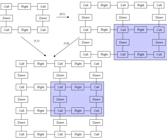
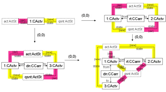
its connectivity and the relative directions. A translation is uniquely determined by the position of the image of the upper left corner (or any other cell) of the original grid in the context of the target grid.Figure 3shows the composition of two translations, where the highlighted rectangles show the new positions of the original grid. We assume that translations occur only rightwards and downwards. The pairs(r,c)labeling the morphisms indicate the offsets at which the nodes of the original grid are found in the new grid. The size of G2is at least equal to that of G1. The
identity morphism is the translation(0,0)from a grid into itself, and morphism composition is the vectorial sum of the translations. We now study the subcategory TGridT, obtained by taking
the structural part of AGridT, i.e. maintaining the type information, but forgetting attributes.
Figure 3: Translation morphism and composition.
In TGridT, a pushout G1
p1
→P←p2 G2 for a span G1
t1
←G→t2
G2 between two grids can be
constructed in the same way as the pushout in Graph if and only if one of the following is true: (1) either t1or t2is an identity;
(2a) t1has a label of the form(r1,0)and G1.ncol==G.ncol AND
(2b) t2has a label of the form(0,c1)and G2.nrow==G.nrow;
(3a) t1has a label of the form(0,c2)and G1.nrow==G.nrow AND
(3b) t2has a label of the form(r2,0)and G2.ncol==G.ncol.
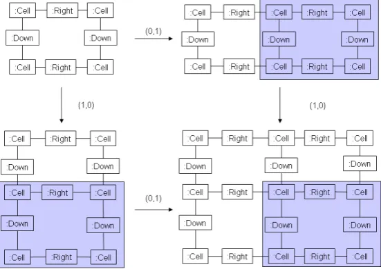
Then, P has size (max(G1.nrow,G2.nrow),max(G1.ncol,G2.ncol)); morphisms p1: G1→
P and p2: G2 →P are labeled by (max(r1,r2)−r1,max(c1,c2)−c1), and (max(r1,r2)−r2,
max(c1,c2)−c2), respectively, so that parallel arrows have the same label (seeFigure 4). The
pushout complement G→x1 C→x2 G0, for the composition G→t1 G1
t2
size(r,c), G1 of size(r1,c1)and G0 of size(r0,c0), uniquely exists only if t1 and t2 satisfy the
constraints above, and has size((r0−r1) +r,(c0−c1) +c), with x1and x2labeled as t1and t2.
Figure 4: The pushout construction for grids
We can now define structural DPO rules in TGridTin accordance to the construction above.
In particular, in order to satisfy the the dangling condition, rules are non-deleting (i.e. L←K
is an identity). The gluing condition, if K→R is not an identity, requires border cells of L to
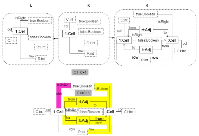
be matched to border cells of the host grid G. The pushout complement object D is now always equal to G. Hence, grids can be generated so that the constraints on their rectangular form are maintained through the pushout construction, without having to adopt regulatory mechanisms for rewriting, such as those needed for the so-called Indian grammars: a set of horizontal rules is there first used to create the upper row, and then vertical rules are applied in parallel to pop-ulate the columns [SK74]. The pushout construction can now be lifted in order to consider also attributes. In particular, as typical of attributed graph rewriting, data morphisms are identities (no domain element can be created or deleted). Hence, the effect of a rule can only be the addi-tion of structural nodes and edges and the deleaddi-tion and creaaddi-tion of attribute edges. Applicaaddi-tion conditions can be used to describe the relations between values. All grids in AGridT can now
be generated by the iterated use of the two rules inFigure 5andFigure 6, in which identifiers of
Adjacencynodes indicate their directions and an application condition defines the coordinates of the new cell.
In both cases, we show the classical representation of DPO rules at the top of the figure, and use, at its bottom, a compact notation, already exploited in [dGB07]: the difference between
K, L, and R is shown by highlighting the deleted and produced parts with different colours and
Figure 5: The rule for letting a grid grow horizontally.
5
Control Flow Rules
Figure 7presents the metamodel triples describing the correspondences induced by assigning to the adjacency relation in the visual representation the semantic meaning of a carrier, along which either data or modifications in the activation state can travel from and to active elements. The left upper part ofFigure 7constitutes the static semantics for the control flow variety on spatial structures, while the right upper part models the data variety, here simplified by considering a simple integer-valued attribute, called level. By applying the construction in [dGB07] one can incrementally define the flow structure through triple graph rules which introduce carriers in correspondence with the installation of adjacency relations in specified directions. Hence, one can model the permeability of the cell wall to control or data flow. As an example, flows could travel rightwards and leftwards, but not downwards and upwards.
A control flow (cf ) rule is a DPO rule in AGraphATG with graphs conforming to the left
upper part ofFigure 7, so that A contains the attribute state with values in some finite domain
ActivationState∈∆.
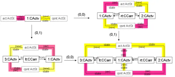
In general, as shown in the rule (in compact form) on the left ofFigure 83, the activation state may vary during transportation, e.g. a flow can decrease its intensity. The element reached by the flow could have possessed some other activation value and the one from which the flow originated may gain a new one, as defined by application conditions. The basic rule on the right ofFigure 8
deals with the case of cells entering an active state as the control flow reaches them traveling the grid rightwards from the origin to the destination, while the origin enters a quiescent state.
Figure 6: The rule for letting a grid grow vertically.
The carrier identifier indicates the value of itsDirectionattribute. Similar rules are defined for other directions, exploiting rotational and mirror symmetries. cf -rules are composed to form more complex ones using a componentwise pushout construction in AGraphATG, as shown in
Figure 9, where L←K→R is the maximal intersection of L1←K1→R1and L2←K2→R2,
all the squares commute and those with curved arrows are pushouts. As an example, directional rules compose through a rule on a single cell passing from the active to the quiescent state.
Figure 10 illustrates the case of the two horizontal movements, while Figure 11 that of one directional and one vertical movement.
Figure 8: A generic rule for transmission of control flows and a basic rule. L 4 4 K l o
o r //
* * R 4 4 L1 K1 l1 o
o r1 //
R1
L2 K2 44
l2
o
o r2 // **
R2 L0oo l K0 r 44//R0
Figure 9: The construction for rule composition.
6
Composing Control Flow and Computation Formulas
We now introduce data-rules to specify the transformation of some attribute according to some formula. These are defined on the type graph in the right upper part ofFigure 7. Data and cf -rules are composed, again with a pushout construction, to produce -rules which both apply the formula and propagate the flow, when an active element is reached by the control flow.
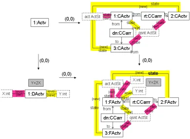
The rule inFigure 12doubles the value oflevel. X and Y are variables to indicate generic instances of an integer. The rules involved in their combination operate on four different types of graphs. The intersection is defined in a type graph where ActiveElementabstracts on
ControlActiveElementandDataActiveElementand has no attribute, while the pushout
object complies with a type graph formed by taking the quotient of the disjoint union of the two type systems fromFigure 7and identifying the activity types in aFullActiveElementtype
Figure 11: The construction of a bidirectional rule.
(abbreviated in FActv). Node morphisms go from less to more specific types.
Figure 12: A rule expressing a computational formula.
InFigure 13, the bidirectional rule ofFigure 11is composed with the formula ofFigure 12, so that the latter is now evaluated only when the activation front leaves an element in both directions. Using different mappings from the intersection to the cf -rule, the formula would be evaluated when the control flow reaches an element from a specific direction. The resulting rule does not specify thelevel values for the other elements. Rules can be applied sequentially or, if they do not conflict on their result, combined to form amalgamated rules to achieve an effect of parallelism [TB94]. As an example, the rule ofFigure 13agrees with itself on any node whose upper and left neighbours are both mapped, by two distinct matches, to the cell identified by 1. Rules can be enriched with parameters and applied via rule expressions to realize complex computations [BKPT00].
6.1 Types of activation in Cyberfilm
The Cyberfilm language [YM02,WMYM08] provides a collection of predefined control flows, associated with program templates defining the loops realizing them, and with sequences of iconic schemes for an intuitive visualization of the main steps in the execution flow. Cyberfilm allows the separated definition of computational formulae and control flow specifications. Hence, the constructions above can be exploited to provide a compositional mechanism for it.
Figure 13: The resulting rule specifying the condition of application.
flashing state of a node Different types of flashing are defined: for example, full flashing indicates
that the node is able to perform reading and writing operations; contour flashing indicates that the node is referenced by other flashing nodes which can perform reading operations, but not change its value; half flashing indicates the activity state of an observer which can change the state of other nodes in a global fashion. Other types of flashing are defined, but in this paper we restrict ourselves to the flow of the full and contour flashing, thus interpreting full flashing as an indication that the formula associated with the node can be evaluated to assign a new value to the node, and contour flashing, as the fact that the value of the node is available for formula evaluation by other nodes.
At any time, a cell is in only one possible state. The control flows of the full and contour flashing can be independent or coordinated. Independent flows can be specified as described in
Section 5, whereas coordinated flows require the identification of the conditions under which a cell is able to receive the contributions of other cells.
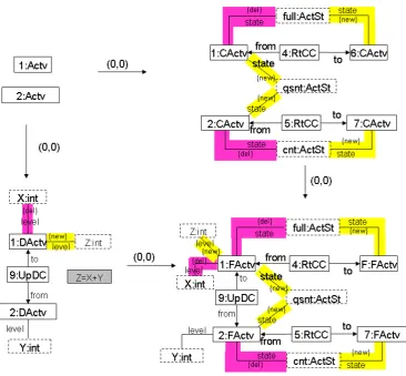
Figure 14shows the composition of a coordinated cf -rule, for rightward transmission of both
full and contour flows, with a formula rule where an element reads the value of its down
Figure 14: The rule resulting from the coordination of movements of full and contour flashing.
In this case, the cf -rule is bound to consider both the full and contour flows simultaneously. The same effect could be achieved by considering the two flows independently.Figure 15shows the first step of the relative construction, in which the rightwards movement for the full flash-ing is combined with the same formula to produce a rule which does not affect the state of the
ControlActiveElementidentified by 2. InFigure 16, the obtained rule is composed with that for rightward movement of contour flashing. While the final effect is the same, the interme-diate step could be combined with other movement rules. Several such rules might be defined, for example to propagate the flow across several cells, so that only some elements are activated.
7
Conclusions
Figure 15: Coordinating movement of the full flashing flow with the formula inFigure 14.
the independent definition of two types of rules, one to specify control flow and the other to specify the actual computations. The construction is symmetrical in control and formula rules, so that it can be flexibly applied starting from either specification. Symmetries between adjacency relations can also be exploited to generate different versions of flows and formulas.
Future work will explore other types of spatial structures, typically trees and pyramids, to define adequate cf -rules, also considering the distinction between formula evaluation on control flows reaching or leaving the involved cells, and develop ways of reasoning about the compati-bility of independent cf -rules (e.g. one for reading and one for writing).
Bibliography
[AFGK02] L. F. Andrade, J. L. Fiadeiro, J. Gouveia, G. Koutsoukos. Separating computation, coordination and configuration. J. of Software Maintenance 14(5):353–369, 2002.
[BG04] P. Bottoni, A. Grau. A Suite of Metamodels as a Basis for a Classification of Visual Languages. In Proc. VL/HCC 2004. Pp. 83–90. 2004.
[BKPT00] P. Bottoni, M. Koch, F. Parisi Presicce, G. Taentzer. Automatic Consistency Check-ing and Visualization of OCL Constraints. In Proc. UML 2000. Pp. 294–308. 2000.
Figure 16: Coordinating movement of the contour flashing flow with the rule ofFigure 15.
[BLG07] P. Bottoni, J. de Lara, E. Guerra. Action Patterns for Incremental Specification of Execution Semantics of Visual Languages. In Proc. VL/HCC 2007. Pp. 163–170. 2007.
[CMR96] A. Corradini, U. Montanari, F. Rossi. Graph processes. Fundamenta Informaticae 26(34):241–265, 1996.
[dBE+07] J. de Lara, R. Bardohl, H. Ehrig, K. Ehrig, U. Prange, G. Taentzer. Attributed graph transformation with node type inheritance. TCS 376:139–163, 2007.
[dGB07] J. de Lara, E. Guerra, P. Bottoni. Triple Patterns: Compact Specifications for the Gen-eration of OpGen-erational Triple Graph Grammar Rules. In Proc. GT-VMT’07. Pp. 81– 95. 2007.
[EEPT06] H. Ehrig, K. Ehrig, U. Prange, G. Taentzer. Fundamentals of Algebraic Graph
Trans-formation. Springer, 2006.
[GEMT00] M. Goedicke, B. Enders, T. Meyer, G. Taentzer. Towards integration of multiple perspectives by distributed graph transformation. In Nagl et al. (eds.), Proc. AGTIVE
1999. Pp. 369–377. 2000.
[GR97] D. Giammarresi, A. Restivo. Two-dimensional languages. In Handbook of Formal
[HKT02] R. Heckel, J. K¨uster, G. Taentzer. Confluence of Typed Attributed Graph Transfor-mation with Constraints. In Proc. ICGT 2002. LNCS 2505, pp. 161–176. 2002.
[HP95] A. Habel, D. Plump. Unification, rewriting, and narrowing on term graphs. Electr.
Notes Theor. Comput. Sci. 2, 1995.
[IPS82] A. Itai, C. H. Papadimitriou, J. L. Szwarcfiter. Hamilton Paths in Grid Graphs. SIAM
J. Comput. 11(4):676–686, 1982.
[KK99] H. Kreowski, S. Kuske. Graph Transformation Units with Interleaving Semantics.
Formal Aspects of Computing 11:690–723, 1999.
[LS04] S. Lack, P. Sobocinski. Adhesive Categories. In Ehrig et al. (eds.), Proc. FOSSACS
2004. Pp. 273–288. Springer, 2004.
[Mos94] P. Mosses. Recent Trends in Data Type Specification. Chapter Unified algebras and abstract syntax, pp. 280–294. Springer, 1994.
[MW93] M. K. M L¨owe, A. Wagner. Term Graph Rewriting: Theory and Practice. Chapter An Algebraic Framework for the Transformation of Attributed Graphs, pp. 185–199. John Wiley and Sons Ltd, 1993.
[Par94] F. Parisi Presicce. Transformations of Graph Grammars. In TAGT. LNCS 1073, pp. 428–442. 1994.
[SK74] R. Siromoney, K. Krithivasan. Parallel context-free grammars. Information and
Con-trol 24:155–162, 1974.
[SWZ99] A. Sch¨urr, A. Winter, A. Z¨undorf. The PROGRES-Approach: Language and Envi-ronment. In Ehrig et al. (eds.), Handbook of Graph Grammars and Computing by
Graph Transformation, Vol. 2. Pp. 487–550. World Scientific, 1999.
[TB94] G. Taentzer, M. Beyer. Amalgamated Graph Transformations and Their Use for Specifying AGG. In Dagstuhl Seminar on Graph Transformations in Computer
Sci-ence. LNCS 776, pp. 380–394. Springer, 1994.
[WMYM08] Y. Watanobe, N. N. Mirenkov, R. Yoshioka, O. Monakhov. Filmification of meth-ods: A visual language for graph algorithms. Journal of Visual Languages and
Com-puting 19(1):123–150, 2008.