Proceedings of the Workshop on the
Layout of (Software) Engineering Diagrams
(LED 2007)
A Pattern-Based Layout Algorithm for Diagram Editors
Sonja Maier and Mark Minas
16 pages
Guest Editors: Andrew Fish, Alexander Knapp, Harald St ¨orrle
Managing Editors: Tiziana Margaria, Julia Padberg, Gabriele Taentzer
A Pattern-Based Layout Algorithm for Diagram Editors
Sonja Maier1and Mark Minas2
Institut f¨ur Softwaretechnologie
Universit¨at der Bundeswehr M¨unchen, Germany
Abstract:The diagram editor generator framework DIAMETAutilizes
meta-model-based language specifications and supportsfree-hand as well asstructured editing. We presented ageneric layout algorithm that meets the demands of this kind of editors. The algorithm combines two concepts, constraint satisfaction and attribute evaluation, to a powerful methodology for specifying the layout for a particular visual language. As thelayoutspecification for this algorithm is rather complex, we encapsulated basic functionality into reusablepatterns. This paper describes this
patternconcept of thegeneric layout algorithm, and shows how they simplify the
layoutspecification of a specific language.
Keywords:Pattern, Constraint Satisfaction, Attribute Evaluation, Visual Language,
Free-hand Editing, Structured Editing
1
Introduction
Several approaches and tools have been proposed to specify visual languages and to generate editors from such specifications. These attempts can be characterized by the way the diagram language is specified and by the way the user interacts with the editor and creates respectively edits diagrams. Most visual languages have a meta-model as (abstract) syntax specification. A model is essentially a class diagram of the data structure that is visualized by a diagram. When considering user interaction and the way how the user can create and edit diagrams,structured editing is usually distinguished fromfree-hand editing. Structured editorsoffer the user some operations that transform correct diagrams into (other) correct diagrams. Free-hand editors, on the other hand, allow to arrange diagram components from a language-specific set on the screen without any restrictions. The editor has to check whether the drawing is correct and what its meaning is. In both cases, alayoutermay be used to beautify the diagram. Infree-hand mode, the editor user has more freedom, which implies that the layouter is more complex.
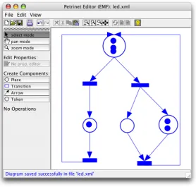
In [MM07] we designed a generic layout algorithm that works for model-based visual lan-guages. It meets the demands of structured as well asfree-hand editing. Our algorithm was designed for the framework DIAMETA, that follows the model-driven approach to specify dia-gram languages. From such a specification an editor, offeringstructured as well as free-hand editing, can be generated. In Fig.1we can see an editor that was generated with DIAMETA.
the world of grammar-based editors, somelayout algorithmshave been established in the past
[Min04]. Ourlayout algorithmoperates on a meta model instead. It allows for defining alayout
that is specialized for a certain model, i.e. a certain visual language.
One frequently used concept is attribute evaluation. An attribute evaluator is fast and best suited if thelayout is unambiguous. This concept cannot deal with the situation that the same diagram may be represented in different ways. Especially infree-hand mode, a conventional attribute evaluator is not sufficient. Another concept that is frequently used forlayout[Min04,
CMP99] is constraint satisfaction. The disadvantages of this concept are that constraint
satisfac-tion is slow in some cases and its behavior is unpredictable in some situasatisfac-tions.
Figure 1: Petri net editor
In [MM07] we presented an algorithm that combines the two concepts, constraint satisfaction and attribute evaluation, to a powerful algorithm that is fast, flexible and behaves exactly the way we desire: Declarative constraints ensure the characteristics of thelayout. If they are not fulfilled, a set of certain attribute evaluation rules is switched on. These rules are evaluated, and the associated attributes are updated.
of abstraction on top of the specification, asdesign patterns [GHJV95] do for object-oriented software design. In order to use such a predefinedpattern, the model must contain some special components, e.g. for theGraphPattern, the model must contain a class representing edges and a class representing nodes.
For most visual languages, standard layout algorithms may be specified, using predefined pat-terns. Using them simplifies thelayoutspecification. If the predefinedpatternsare not sufficient, e.g. for unusual visual languages or a fancy layout, thepatternsmay be adjusted to the special needs or newpatterns may be created. And of course it is also possible to use the algorithm in the traditional way and benefit from the complete functionality thegeneric layout algorithm
offers.
In Sect. 2 we introduce the model of Petri nets, the visual language that is used as a running example. In Sect. 3 we explain the generic layout algorithmthat we have proposed for meta model based editors. In Sect. 4 we introduce thepatternconcept for thegeneric layout algorithm. In Sect. 5 we show how to use this concept to create thelayout for Petri net editors. Sect. 6 summarizes some implementation details and gives an overview of DIAMETA, the environment in which thepatternconcept was tested. Sect. 7 concludes the paper.
2
Running Example
In this section we introduce an editor for Petri nets as running example. First we describe the underlying meta model of the Petri net language. Then we explain how the diagram is visualized. Finally we give a short overview of thelayoutthat we are going to define throughout the paper.
Each diagram consists of a finite set of visual components. In Petri nets, these are places, transitions, tokens, and arrows between places and transitions. Each component is determined by its attributes.
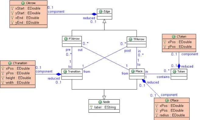
Fig.2shows the meta model for Petri nets. It contains the classNodeas an abstract base class of a Petri net’sPlaceorTransition. The classesPlaceandTransitionhave a member attribute
label. Edgeis the abstract base class of a connection between places and transitions. Concrete classes of the abstract model arePlace,Transition,PTArrow,TPArrow, andTokenrespectively. Transition-Place relations are represented by the associations betweenTransition,TPArrowand
Place, Place-Transition relations by the associations betweenPlace,PTArrowandToken. Place-Token relations are represented by the association between the classesPlaceandTransition.
In the meta model, the abstract syntax is described. Besides that, some aspects of the concrete syntax are included. This additional information is needed to perform layout computations. The classesCPlace,CTransition,CArrowandCTokenrepresent aspects of the concrete syntax.
A place is visualized by a circle whose center position is determined by its attributes (xPos,
yPos) and its radius by the attribute radius. A transition is visualized by a square whose cen-ter position is defined by the coordinate point (xPos,yPos) and its size by the attributeswidth
andheight. A token is visualized by a circle whose center position is again defined by (xPos,
yPos). Its radius is a fixed value that cannot be modified by the user. PTArrow andTPArrow
are visualized by arrows whose position is defined by its two end points, i.e. by two coordinate pairs (xStart,yStart) and (xEnd,yEnd).1 In Fig. 1we can see a sample Petri net, visualized as described above, and layouted (incrementally) as described in the following.
We are going to specify alayoutfor the Petri net editor that is based on the model presented above. During user interaction, we want to support the user with some special behavior. After user interaction, we want to get a beautified diagram as result.
• After user interaction: Arrows start and end exactly at the border of a component, i.e.
exactly at the border of a transition or place. Arrows must have a minimal length, i.e. the components must have a minimal distance. Tokens are completely inside a place. They may not intersect the border line of the place. If possible, tokens are arranged as a list, as long as the list fits into the place.2
• During user interaction: When we move a place (or change the size of a place), arrows
and tokens have to follow the place. When we move a transition (or change the size of a transition), arrows also have to follow the transition. This gives the user an easy and intuitive way of changing the visual appearance of the Petri net. He may for example rearrange tokens and places without changing the semantics of the diagram. When we move an arrow or token, nothing else is changed. With this functionality, the user may change the dynamic behavior of the Petri net. He may for example move a token from one place to another.
In our specification we make use of three patterns. TheGraphPattern being responsible for
layoutingthe arrows, theListPatternthat is responsible for arranging the tokens inside a place and theContainmentPatternthat ensures that tokens are completely inside the place. To demon-strate the possibilities offered by the concept, we will adjust a patternand we will add some additional functionality that is not supported by thepatterns.
1 They can be substituted by a list of bends. The editor that was created via D
IAMETAactually supports bends.
3
Generic Layout Algorithm
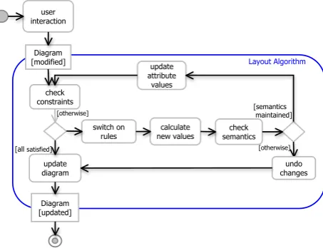
In Fig.3we can see a birds-eye view of thelayout algorithmthat has been presented in [MM07]. The algorithm is based on the idea that we have a set of declarative constraints (and a set of all attributes), that assure the characteristics of thelayout. If all constraints are satisfied, thelayouter
terminates. If one or more constraints are not satisfied, thelayouterneeds to change some at-tributes to satisfy the constraints. Therefore it switches on one or more attribute evaluation rules. These rules in turn are responsible for updating the attributes, i.e. to satisfy the constraints.
In this section we describe thislayout algorithmin more detail. First we describe the input pa-rameters of thelayouter. Then we summarize what components thelayout specificationconsists of. As a last step we describe thelayout algorithmitself. In the next section we will introduce thepatternconcept for thislayout algorithm.
3.1 Input
The algorithm gets as input one or two sets of attribute values - the old values(values before user interaction), theuser-desired values(values after user interaction) or both. Furthermore, the
layouteris aware of the current state. It knows whether the user is in the process of modifying a component, e.g. is currently moving a place, or has finished a modification already. It also knows, which component(s) the user has changed. In addition, thelayouter has access to the model of the visual language.
We have to distinguish three types of user interaction: adding, modifying and removing. The selection ofold valuesanduser-desired valuesdepends on the type of user interaction. When the user adds a component at a desired position, thelayoutergets one set of values as input - the
user-desired values. When the user modifies a component, e.g. moves a place from the position
characterized byxPosold andyPosold to a new positionxPosuser andyPosuser, thelayouter has
two sets of values as input - theold valuesand theuser-desired values. In case of deletion, the
layoutergets only theold valuesas input.
10
Diagram [updated] Diagram
[modified] Layout Algorithm
calculate new values switch on
rules check
constraints
update diagram
[otherwise]
[all satisfied]
check semantics
[otherwise]
[semantics maintained]
undo changes user
interaction
update attribute
values
After user interaction During user
interaction Before user
interaction
Figure 4: Moving a place
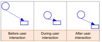
We distinguish between two states, during modificationandafter modificationthat we treat in different ways. During modificationonly the layouter is called, after modificationfirst the model is updated and then thelayouteris called, using the updated model.During modification, somelayoutingconstraints should be satisfied immediately. The satisfaction of other constraints may be postponed to the end of the user interaction. Suppose we change the position of a place, as we can see in Fig4. While we move the component (during modification), we want arrows to follow the place. As thelayouter is responsible for updating the attributes, he needs to be called several times during modification of the diagram via user input in order to update the arrows. After we finished moving the place, for example, we want to satisfy the constraint that arrows have a minimal length. If an arrow does not satisfy this constraint, it is extended automatically. Minimizing the number of computations during user interaction not only speeds up the computation of the new visualization, it also gives the user more freedom.
Another aspect we take care of is the information, what component, i.e. what attributes, the user changed. In our example we distinguish between moving arrows and moving places or transitions. When we move an arrow, we just want the arrow to be moved. The places and transitions remain unchanged. If we move a place or transition, we want the arrows to remain connected to these components, and hence the arrows are changed.
3.2 Layout Specification
The layouter uses the attributes, the state and the model of the visual language to calculate
new valuesthat represent the updated diagram. To do that, it needs a layout specification, as introduced in [MM07]. This specification consists of a set of constraints, each of them associated with a concrete class likePlaceorPTArrow. For every constraint there exists a list of attribute evaluation rules. If a constraint is violated, it is its evaluation rules’ task to update attributes such that the constraint is satisfied (again).
The constraints and attribute evaluation rules use the standard OCL syntax, as specified in
[OMG06]. Onlycurrent valuesare changed during execution of thelayout algorithm. All other
attributes remain unchanged. Intermediate results are created eachlayoutiteration.
Constraints are responsible for switching on and off attribute evaluation rules. Attribute eval-uation rules are responsible for calculating the set ofnew values. For example, constraint (1) switches on rule (2) ifxPos≤in.xPos. If this is not the case,xPosremains unchanged.
[after modification]xPos > in.xPos (1)
We may restrict constraints and attribute evaluation rules to be checked and executed only if we are in a special state (indicated by[state]in front of the constraint or rule). For example, if we add[after modification]in front of the constraint, this constraint is checked after modification. Otherwise, this constraint is checked each time thelayouteris called.
We may also add[o1 changed]in front of the constraint. This means that the constraint is only executed if one of the attributes of the object o1 has changed.3
3.3 Layout Algorithm
In Fig.3 we can see a birds-eye view of the generic layout algorithm. Thelayouteris called each time the diagram was changed via user interaction. The set ofcurrent valuesconsists of
user-desired valuesfor the attributes changed via user interaction, and old valuesfor attributes the user did not change. All potentially violatedlayoutconstraints (that need to be checked for the current state) are checked, and the rules that were switched on are collected. Thereafter the
new valuesof the attributes are calculated via attribute evaluation.
The current valuesare substituted by thenew values and the constraints are checked again,
since new constraints may have become unsatisfied due to changes performed by thelayouter. If all constraints are satisfied, thelayoutersucceeds and reports allnew values. Otherwise, the
layouterhas to evaluate the rules again. If thelayouterdoes not succeed after a certain number of iterations (may be user defined), thelayouterstops and returns theuser valuesas result.
4
Pattern Concept for the Layout Algorithm
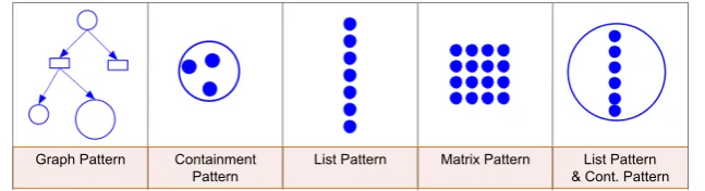
Creating an editor with DIAMETA is tool supported. The only part the editor developer had to write by hand had been thelayouter. With thelayout algorithmpresented above, the editor developer is no longer burdened with this task. He now only has to provide alayout specification. We are aware that writing such a specification is still rather complicated and complex. There-fore we encapsulated basic functionality, as it is done in [SK03,Sch06], and give the user the opportunity to use thesepatterns. In Fig.5we can see somepatternsthat were already defined.
GraphPattern,ContainmentPatternandListPatternwill be explained in the next section, as they form the basis of thelayout specificationfor the Petri net editor.
Graph Pattern Containment Pattern
List Pattern Matrix Pattern List Pattern & Cont. Pattern
Figure 5:GraphPattern,ContainmentPattern,ListPattern,MatrixPattern
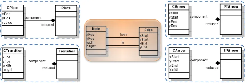
In order to use thesepatterns, the user simply has to specify whichpatternhe wants to apply on what part of the model. For example, for theGraphPattern, he has to specify which component plays the roleNode, and which component the roleEdge. For our Petri net editor, places and transitions will play the role Node and arrows will play the role Edge. In our meta model, places are represented by the two classesCPlaceandPlace and transitions by the two classes
CTransitionandTransition. Arrows are represented by the two classesCArrowandPTArrowor
by the two classesCArrowandTPArrow, as shown in Fig.6.
The editor developer has the opportunity to adjust thesepatternsto his own needs. He may also combine differentpatterns, or refine apattern. Of course he may also add additional functionality or create newpatternsfrom scratch.
4.1 Pattern Requirements
Apatterncontains a set of constraints and corresponding attribute evaluation rules. These con-straints and attribute evaluation rules need some associations and attributes for their calculations. Consequently, apatternmay only be used if some requirements are fulfilled. In Fig.6(in the middle) we see the requirements that need to be met in order to use theGraphPattern. There need to be two associations between Node andEdge with the roles from andto respectively.
Nodemust have the attributesxPos,yPos,widthandheight.Edgemust have the attributesxStart,
yStart,xEndandyEnd.
Figure 6: Requirements for theGraphPattern
In our example place does not offer the attributeswidth andheight. All other requirements are already met. We could add these attributes, but we do not want to change the meta model. In this case, the editor developer may introduce a mapping between a required component and another available component. We introduce a bidirectional mapping betweenheightandradius
and a bidirectional mapping betweenwidthandradius:4
height ← 2∗radius width ← 2∗radius
radius ← height/2 radius ← width/2
4.2 Pattern usage and Pattern adjustment
If all requirements are met, thepattern may be used (pattern usage). A pattern consists of a set of constraints and attribute evaluation rules. E.g. theGraphPatternconsists of the following constraints and attribute evaluation rules.
The following four constraints (left side) associated with the classes PTArrowandTPArrow
assure that arrows start and end exactlyat the top or bottom of a component, as we can see in Fig.4. (xPos,yPos) is located in the top left corner of a component. The first (last) two constraints are checked if the component, at which the arrow starts (ends) has changed. The associated attribute evaluation rules (right side) update arrows, if they are not at the right position.
[from changed]xStart = f rom.xPos+f rom2.width xStart ← f rom.xPos+ f rom2.width
[from changed]yStart = f rom.yPos+f rom.height yStart ← f rom.yPos+f rom.height
[to changed]xEnd = to.xPos+to.width2 xEnd ← to.xPos+to.width2
[to changed]yEnd = to.yPos yEnd ← to.yPos
To assure that arrows have a minimal length, we introduce a constraint associated with the classesPTArrowandTPArrow. This constraint is checked after user interaction has finished:
[after modification](xEnd−xStart)2+ (yEnd−yStart)2>1000
The associated rules extend an arrow, if it is shorter than the minimal length required. If the component, at which the arrow starts (ends) has changed, the component, at which the arrow ends (starts) is moved. As the arrow stays connected to this component, it is automatically extended to the required length.
[from changed]to.xPos ← to.xPost(i−1)+
to.xPost(i−1)−f rom.xPos |to.xPost(i−1)−f rom.xPos|
[from changed]to.yPos ← to.yPost(i−1)+ to.yPost(i−1)−f rom.yPos |to.yPost(i−1)−f rom.yPos|
[to changed] f rom.xPos ← f rom.xPost(i−1)+
f rom.xPost(i−1)−to.xPos |f rom.xPost(i−1)−to.xPos|
[to changed] f rom.yPos ← f rom.yPost(i−1)+ f rom.yPost(i−1)−to.yPos |f rom.yPost(i−1)−to.yPos|
In eachpatternwe introduced some constants. These constants have an initial value and may be overridden by the user (pattern adjustment). They are used in the constraints and attribute evaluation rules. E.g. for theGraphPattern, the attributeminLength(the 1000 in the constraint) may be overridden. This changes the minimal length of an arrow. This mechanism madepattern
more flexible. Experiments showed that they were now applicable in more situations.
4.3 Pattern combination and Pattern refinement
It is possible to use more than onepatternforlayout specification(pattern combination). In our example, we will combine the twopatterns ContainmentPatternandListPattern. The Contain-mentPatternwill be responsible to keep tokens inside a place. TheListPatternis responsible for arranging tokens as a list, if the constraints of theContainmentPatternstill can be satisfied.
Pattern Pattern refinement
Figure 7:Pattern refinement
In our example, first theListPattern is applied, and then the
ContainmentPattern. This mechanism will be substituted by an
enhanced priority concept in future implementations.
We may also add additional constraints and attribute evalu-ation rules to a pattern (pattern refinement). In our example we add a constraint that assures that transitions have a minimal width and height (Fig.7). Up to now, all constraints and attribute evaluation rules are collected. No simplification or error check is utilized. The editor creator has to ensure that constraints and attribute evaluation rules are reasonable.
5
Pattern-Based Layout for the Petri net editor
We now explore a concrete example - thelayoutdeclaration for the Petri net editor. We present thepatternsthat are used in more detail, and show how they are adjusted, combined and refined to the language specificlayoutdesired.
5.1 ContainmentPattern
TheContainmentPattern assures that components are completely inside a surrounding
compo-nent. They may not intersect the border line of the surrounding compocompo-nent.
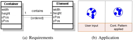
In order to apply theContainmentPattern, the model must contain the following components. BetweenContainer andElement, there must be a 1-to-many association. Container must have the attributeswidth,height,xPosandyPos.Elementmust have the same attributes (Fig.8).
(a) Requirements
User input Cont. Pattern applied
(b) Application
Figure 8:ContainentPattern
We apply theContainmentPatternto places asContainer, and tokens asElement. In order to use the pattern we need to add the attributeswidthandheightto places and tokens. For places we introduce a bidirectional mapping betweenheightandradiusand betweenwidthandradius, as described in Sect.4.1. For tokens, these are fixed values: 20 for both, an unidirectional mapping (height←20,width←20).5 In Fig.8we see an excerpt of a Petri net. On the left side we see the user input, on the right side the result after applying theContainmentPattern.
5 Note that all tokens are moved inside the square width*height, not into a circle. To change this, we would need
5.2 ListPattern
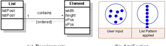
The ListPatternis responsible for arranging a set of components as a list. The ListPattern re-quires that the meta model contains a 1-to-many association betweenListandElement. Further-more, theList must have the attributeslistPosX andlistPosY. These are the coordinates where the list starts. Elementmust have the attributeswidth, height, xPosandyPos. We can see the requirements in Fig.9.
(a) Requirements
User input List Pattern
applied
(b) Application
Figure 9:ListPattern
We apply theListPatternto places asListand tokens asElement. In order to use thepattern,
User input LP & CP applied
Figure 10: Cont. andListPattern
we must add the attributeslistPosXandlistPosYto place.
For listPosX and listPosY we define a bidirectional
map-ping. (listPosX ← xPos+width/2, xPos← listPosX− width/2 andlistPosY ←yPos, yPos←listPosY). Transi-tionalready has all attributes required.
The ListPatternprovides several customization options.
For example we may choose whether to align elements ver-tically or horizontally. By default they are aligned verti-cally, as used for our Petri net editor. In Fig.9we see an excerpt of a Petri net. On the left side we see the user input, and on the right side the result after applying theListPattern. In Fig.10
we can see what happens if we apply both - theContainmentPatternas well as theListPattern.
5.3 GraphPattern
As the third and lastpatternwe use theGraphPattern, thepatternthat was already described in the last section. It demands that arrows start and end at the border of transitions and places.
User input Graph Pattern applied
Figure 11:GraphPattern
In addition, arrows must have a minimal length. The
Graph-Patternmay be applied if the requirements shown in Fig.6are
met. We apply the GraphPattern to places and transitions as
Nodeand arrows asEdge. TheGraphPatternalso provides sev-eral customization options. For example, we may change the minimal length of arrows. This opportunity is used in order to specify ourlayout. Or we may arrange components from left-to-right, instead of top-to-bottom. In Fig.11we can see the user
5.4 Complete Layout
To demonstrate the simplicity and flexibility of the pattern concept, we include all concepts described in Sect. 4 in the complete layout. We use thepatternsdescribed above (pattern usage
andpattern combination). We change the minimal length of arrows required (pattern adjustment) and we require that transitions must have a minimal size (pattern refinement). We override the attributeminLengthof theGraphPatternto change the minimal length of arrows, and we add an additional constraint and its corresponding attribute evaluation rules to assure the minimal size of transitions. The interesting part of the layout specification is the following:
gp = new GraphPattern(CArrow,CPlace,CTransition); lp = new ListPattern(CPlace,CToken));
cp = new ContainmentPattern(CPlace,CToken);
gp.adjust("minLength := 100");
Constraint constr = new Constraint("width > 100",CTransition); constr.addRule("width := width + 10");
gp.refine(constr);
6
Implementation
In this section, we will give an overview of DIAMETA, the environment in which the algorithm was tested and explain how the algorithm was integrated in the framework. We will then examine the layout algorithm and the pattern concept in terms of usability and performance.
6.1 Integration of the Layout Algorithm inDIAMETA
DIAMETA provides an environment for rapidly developing diagram editors based on meta-modeling. Each DIAMETA editor is based on the same editor architecture which is adjusted to the specific diagram language.
6.1.1 Architecture
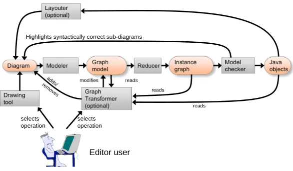
Fig12. shows the structure which is common to all DIAMETAeditors [Min06a,Min06b]. The editor supportsfree-hand editingby means of the included drawing tool which is part of the editor framework, and can be adjusted by the DIAMETADesigner. With this drawing tool, the user is able to create, arrange and modify the diagram components of the particular diagram language. Editor specific program code, which has been specified by the editor developer and generated by the DIAMETADesigner, is responsible for the visual representation of these language specific components. The drawing tool creates the data structure of the diagram as a set of diagram components together with their attributes (position, size, etc.).
Diagram
Drawing tool
Editor user
selects operation
5
Graph model
Modeler Instance
graph
Reducer Model
checker
Java objects
selects operation
Graph Transformer
(optional) reads
reads
adds/
removes modifies reads
Layouter (optional)
Highlights syntactically correct sub-diagrams
Figure 12: Architecture of a diagram editor based on DIAMETA
correct and provides visual feedback to the user by drawing those diagram components in a certain color; errors are indicated by another color. However, the model analyzer not only checks the diagrams abstract syntax, but also creates the object structure of the diagram’s syntactically correct sub diagram.
Then thelayouteris (optionally) called. It modifies attributes of diagram components and thus the diagramlayoutis based on the (syntactically correct sub diagrams) object structure that was created in the last processing step.
6.1.2 Framework
This section completes the description of DIAMETA and outlines its environment supporting specification and code generation of diagram editors that are tailored to specific diagram lan-guages. The DIAMETA environment shown in Fig. 13 consists of an editor framework, the DIAMETADesigner and the DIAMETALayout Generator.6
The framework that is basically a collection of Java classes, provides the generic editor func-tionality, which is necessary for editing and analyzing diagrams. In order to create an editor for a specific diagram language, the editor developer has to provide two specifications: First, the abstract syntax of the diagram language in terms of its model, and second, the visual appear-ance of diagram components, the concrete syntax of the diagram language, the reducer rules and the interaction specification. Besides that, he may provide alayout specification, if he wants to define a specificlayout. We may use the pattern concept in this specification.
DIAMETAcan either use the Eclipse Modeling Framework (EMF version) [AKRS06,Min06a] or MOFLON (MOF version) [BBM03,Min06b] for specifying language models and generating their implementations. Our algorithm implementation is based on the EMF version. But with minor changes, the algorithm and the pattern concept may also work with the MOF version in-stead. A languages class diagram is specified as an EMF model that the editor developer creates
Editor developer Diagram editor DiaMeta editor framework DiaMeta Designer DiaMeta Generated program code EMF Compiler operates ECore Modeller ECore Specification operates DiaMeta Layout Generator Generated Program code Editor Specification Layout Specification
Figure 13: Generating diagram editors with DIAMETA
by using the EMF modeler. The EMF compiler, being part of the EMF plugin for Eclipse, is used to create Java code that represents the model. The EMF compiler creates Java classes (respec-tively interfaces) for the specified classes. The editor developer uses the DIAMETADesigner for specifying the concrete syntax and the visual appearance of diagram components, e.g. places are drawn as circles, transitions as rectangles, andedges as arrows. The DIAMETADesigner generates Java code from this specification. In addition, we can provide alayout specification, e.g. we may iapply theGraphPatternto arrows, places and transitions. The DIAMETALayout
Generator generates Java code from this specification. This Java code, together with the Java
code generated by the DIAMETADesigner, the Java code created by the EMF compiler and the editor framework, implement an editor for the specified diagram language.
6.2 Usability and Performance
In the last subsection we described how thelayout algorithm(and thus thepattern concept) was integrated in DIAMETA. We examine the algorithm in terms of usability and performance, as it is done in [DFAB98].
a specific visual language. The editor developer himself may decide how much effort he wants to put onto thelayout specification.
The weak point of most algorithms solely based on constraint satisfaction is performance
[CMP99]. In our algorithm we provide the constraints as well as the solution to these constraints
(attribute evaluation rules). This has the consequence that layout computation is no longer time consuming. Thus performance is (up to now) no issue. E.g. for the presented example, layouting a diagram that contains 200 components (50 places, 50 transitions, 50 tokens and 50 arrows) takes less than 0.5 seconds. For further details, please refer to [MM07].
7
Conclusions and Prospects
The diagram editor generator framework DIAMETAmakes use of meta-model-based language specifications and supportsfree-hand as well asstructured editing. The algorithm described in [MM07] is a modular andgeneric layout algorithmthat meets the demands of this kind of edi-tors. The fundamental concept of the algorithm is constraint satisfaction combined with attribute evaluation in the sense that constraints are used to activate particular attribute evaluation rules. This combination gives thelayouterthe flexibility it needs to supportfree-handas well as struc-tured editing. By means of the example we saw that it is possible to define alayout algorithmfor diagrams that supports the user during user interaction (incrementally), and meanwhile grants the user plenty of freedom. Furthermore, alayouteddiagram is displayed at any time.
We realized that writing such a specification is rather complicated. Therefore we encapsulated basic functionality, and give the user the opportunity to use (and reuse) thesepatterns. Patterns
introduce another level of abstraction on top of the specification, asdesign patternsdo in object oriented software design. Apatternis basically a set of constraints and attribute evaluation rules that is tailored to a specific problem, e.g. to the problem of arranging arrows in a graph-based visual language. Patterns may be used if some requirements are satisfied. It may be adjusted to a visual language as required. The editor developer has the opportunity to combine different
patternsor refine apattern. Of course he may also add additional functionality or create new
patternsfrom scratch. Using thepattern concept made writing a specification easier, without
loosing the flexibility of the original, sufficiently efficientgeneric layout algorithm.
Up to now creating a specification or defining apatternhas to be done by hand. The next step will be to introduce GUI support for creatingpatternsand also for creating a whole specification. Extensive case studies are planned, and may lead to an enhancedpattern concept. The exten-sion will include a priority concept for constraints and will offer a possibility to integrate existing
layouterand constraint solver. We will apply the concept to graph-based as well as other visual languages. We will examine the applicability to diagrams of different sizes. We will define different views for the same visual language. Till now we focused on an incremental layout, in future case studies we will also examine a complete automatic layout. We will investigate
free-handas well asstructured editing.
Bibliography
[AKRS06] C. Amelunxen, A. K¨onigs, T. R¨otschke, A. Sch¨urr. MOFLON: A Standard-Compliant Metamodeling Framework with Graph Transformations. In Rensink and Warmer (eds.),Model Driven Architecture - Foundations and Applications: Second
European Conference. Lecture Notes in Computer Science (LNCS) 4066, pp. 361–
375. Springer Verlag, Heidelberg, 2006.
[BBM03] F. Budinsky, S. A. Brodsky, E. Merks.Eclipse Modeling Framework. Pearson Edu-cation, 2003.
[CMP99] S. S. Chok, K. Marriott, T. Paton. Constraint-Based Diagram Beautification. InVL
’99: Proceedings of the IEEE Symposium on Visual Languages. P. 12. IEEE
Com-puter Society, Washington, DC, USA, 1999.
[DFAB98] A. Dix, J. Finley, G. Abowd, R. Beale. Human-computer interaction (2nd ed.). Prentice-Hall, Inc., Upper Saddle River, NJ, USA, 1998.
[GHJV95] E. Gamma, R. Helm, R. Johnson, J. Vlissides. Design Patterns. Addison-Wesley Professional, January 1995.
[Min04] M. Minas. VisualDiaGen – A Tool for Visually Specifying and Generating Visual Editors. InApplications of Graph Transformation with Industrial Relevance, Proc. 2nd Intl. Workshop AGTIVE’03, Charlottesville, USA, 2003, Revised and Invited
Papers. Lecture Notes in Computer Science 3062. Springer-Verlag, 2004.
[Min06a] M. Minas. Generating Meta-Model-Based Freehand Editors. Appears in Electronic Communications of the EASST, Proc. of 3rd International Workshop on Graph Based Tools (GraBaTs’06), Natal (Brazil), September 21-22, 2006, Satellite event of the 3rd International Conference on Graph Transformation, 2006.
[Min06b] M. Minas. Generating Visual Editors Based on Fujaba/MOFLON and DiaMeta. In Giese and Westfechtel (eds.),Proc. Fujaba Days 2006, Bayreuth, Germany, Septem-ber 28-30, 2006. Pp. 35–42. 2006. Technical Report tr-ri-06-275 Universit¨at Pader-born, Fakult¨at f¨ur Elektrotechnik, Informatik und Mathematik, Institut f¨ur Infor-matik.
[MM07] S. Maier, M. Minas. A Generic Layout Algorithm for Meta-model based Editors.
InApplications of Graph Transformation with Industrial Relevance, Proc. 3rd Intl.
Workshop AGTIVE’07, Kassel, Germany. 2007.
[OMG06] OMG. Object Constraint Language (OCL) Specification, Version 2.0. 2006.
[Sch06] C. Schmidt. Generierung von Struktureditioren f¨ur anspruchsvolle visuelle
Sprachen. PhD thesis, Universit¨at Paderborn, D-33098 Paderborn, Germany, 2006.