CARBON DIOXIDE GEOSEQUESTRATION: OPTIMUM GAS
INJECTION TEMPERATURE REQUIRED FOR CAP ROCK
GEOMECHANICAL INTEGRITY
Adango Miadonye
[a]and Mumuni Amadu
[b]Keywords: Carbon dioxide, tensile failure, shear failure, steady state, geosequestration, diffusivity, thermophysical.
In the efforts to mitigate the unprecedented anthropogenic carbon dioxide presence in the atmosphere, the decision to store this greenhouse gas in geologic repositories has received global appreciation with assured technical and financial viability. The implication is that the injection temperature of flue gas in the potential geologic sites will be typically those encountered in combustion power plants. This, obviously has a geomechanical consequence considering the fact that heat transferred from the aquifer to the low permeability cap rock will cause excessive pore pressure build up due to poor pore pressure diffusion characteristics of these rocks. While these low permeability rocks are required to provide stratigraphic trapping mechanisms such excessive pore pressure build up can result in compromising the geomechanical integrity. This article has used heat transfer theories and geomechanical concepts to obtain steady state temperature distribution in cap rocks for temperatures ranging from 50 to 8000C. In so doing, cap rock critical temperatures for tensile and shear failures
have been established for a potential on-site gas injection into saline aquifers.
* Corresponding Authors
E-Mail: [email protected]
[a] Department of Chemistry, Cape Breton University, P.O. Box 5300, Sydney, NS, Canada.
[b] Department of Process Engineering and Applied Science, Dalhousie University, Halifax, NS, Canada.
Introduction
In the deeper zones of the sedimentary basin that have for geologic years been cut off from oxygen supply there exist formations containing ultra-high saline waters. The saline formations are natural, salt-water-bearing intervals of porous and permeable rocks that occur beneath the level of potable groundwater. On the basis of mean global geothermal and/or geostatic gradient it is estimated that such a geologic repository must be located at least 2500 ft below mean sea level.1,2
This mean depth ensures a supercritical state where
the gas occupies less volume than in the non-super critical state. One geologic condition for such a deep sequestration is the existence of thickness of rocks or cap rocks above the potential injection zones to act as a geologic seal.
Combustion power plants are the most single stable and intensive carbon dioxide emitters. The CO2 concentration
depends on whether the fuel is gas or coal, on the particular power station technology notably pulverised coal plants (PF), natural gas combined cycle plants and integrated combined gas cycle plants and the age of the plant. In all combustion technologies flue gas production with different concentrations of carbon dioxide is measured per megawatt hour of electrical energy generation. Natural gas combined cycle has the lowest carbon emission while the pulverized coal technology generates the greatest carbon concentration in the flue gas.3 To mitigate global warming by carbon
emission, carbon dioxide capture and geological storage is widely seen as a cost effective way to reduce industrial CO2
emissions into the atmosphere. While the capture of anthropogenic carbon dioxide from combustion power plants and its geological sequestration have been universally
accepted as a technically and economically feasible mitigating step in reducing global warming the need to embark on cost effective and environmentally friendly carbon sequestration is essential. This is because carbon capture and its ultimate geological storage is an additional cost to the power provider unlike the case where carbon sequestration through carbon dioxide enhanced oil recovery is a value added oriented project in the petroleum industry.
In the carbon dioxide capture and storage chain the most single expensive step is that connected to capture. The global availability of the saline aquifers makes it possible for future sequestration projects to be located at injection sites and this has the obvious advantage that flue gas captured from coal combustion processes can be injected directly into saline aquifers. This option reduces transportation cost. The high temperatures of the injection gas will result in geomechanical problems in the cap rock of the saline aquifer that is supposed to offer long term hydrodynamic trapping. It is also necessary to determine the extent to which direct flue gas from the combustion plant will have to be cooled to subcritical temperatures required for avoiding two phase flow in the well bore that can lead to poor injectivity in the injection interval due to gravity segregation.
Theoretical Development
For heat transfer processes governed by pure diffusion a characteristic diffusive time lag parameter4 can be defined
for the system as the time required for steady state heat transfer conditions where temperature is a function only of space coordinate in the system. Normally the smaller the coefficient of heat diffusion the bigger the diffusive time lag. In the case of carbon dioxide injection into saline aquifers, two mechanisms of heat transfer can be distinguished. They are heat transfer by convective processes involving mass transfer and heat transfer by diffusion that depends on the effective diffusion coefficient of the system. For a typical carbon sequestration projects seeking to reduce global warming the anticipated high injection rates, coupled with the conventional requirement for higher injection rates required for limiting capillary forces effect in the two face flow system will result in a convective dominated heat transfer. The steady state heat transfer in such a system will be achieved well within the time frame of fluid injection and possibly earlier than will be expected for diffusive dominated heat transfer. Since the source of heat transfer to the cap rock is the heat of the injected fluid in the aquifer the temperature profile field of the aquifer is the governing factor for that of the cap rock. Consequently, the steady state temperature of the cap rock that is required for obtaining knowledge about final pore pressures and stress conditions of the cap rock will be established by the steady state temperature field of the aquifer. This requirement justifies the steady state temperature computations in this paper using existing steady state solutions for the combined aquifer and cap rock heat transfer problem.
Tensile Failure Criterion
The following are the assumptions considered pertinent for the derivation of tensile and shear failure under undrain loading:
1. The only source of stresses (vertical and horizontal principal stresses) in the shale column is that derived from the overburden material. In this regard stresses due to tectonic forces are neglected.
2. for simplicity a normally pressure shale lithology or column is assumed
3. Mean global values of hydrostatic and geostatic pressure gradients are considered to be 0.46 and 1 psi per foot respectively
4. The aquifer is very extensive and not confined so that injected gas rising to the top of the formation will migrate under the cap rock without exerting significant pressure at the base of the cap rock to constitute a source of stress in the shale column.
5. The injection of supercritical carbon dioxide into a saline aquifer constitutes a two phase flow called drainage. The hydrodynamics of such a system depends on dimensionless parameter called gravity number which is the ratio of buoyancy forces to viscous forces. A high value of this parameter means that buoyancy forced dominant and this will cause injected gas to rise to the top of the aquifer
earlier before injection stops. On the contrary a low value means viscous dominant hydrodynamics which will cause injected gas to predominantly move in a radial direction. We assume a high injection rate characteristic of carbon geosequestration in response to high carbon dioxide generation from a medium power plant. Under such conditions stresses on the base of the cap rock which could be transmitted to the cap rock will be negligible.
For fluid injection under non-isothermal conditions total horizontal stress consists of the effect of fluid pressure and thermal stress effect given as:
(1)
whereohare total horizontal stress, initial
horizontal stress, vertical stress and Poisson’s ratio, respectively.
It has been reported5,6 that the change in vertical stress is
exactly equal to the increase in pore fluid pressure due to thermal loading. This is given as:
(2)
The horizontal stress increase due to thermal loading of pore fluid is given by using the Poisson’s effect as:
(3)
SfwPpare thermal expansivity of rock solid
grains, thermal expansivity of fluid, pore-water compressibility, porosity of sediment, pore pressure change and temperature change respectively.
Initial horizontal stress is given by:
(4)
where Gst and D are mean value of geostatic gradient (1
psi/foot) and depth respectively.
Substitution into Eqn. 2 gives total horizontal stress as:
(5)
β
1- 2ν ν
σ = Δσ +v Δσ +z Δ + σ
hT 1- ν 1- ν 1- ν oh
E T
α 1-φ +φα
s
f
Δ
p
=
Δ
φ
w
P
T
c
α 1- φ + φαs
1- 2ν f
Δ p= Δ
1- ν wφ
P T
c
1- 2ν
σ = st
oh 1- ν G D
s f
hT
w
1
1 2 1 2
1 1 1
E
T D
c
For tensile failure the following stress conditions7 must be
met:
(6a) (6b)
where Pp, Th, Tv, h, v are pore pressure, tensile strength in
the horizontal direction, tensile strength in the vertical direction, horizontal stress and vertical stress respectively. Eqn. (6a) defines tensile failure in the horizontal direction while (6b) defines tensile failure in the vertical direction. The sum of the stress components on the right hand sides of Eqn. (6a) and (6b) gives total stresses, horizontal and veridical stresses respectively. For failure in the horizontal direction the failure stress and pore pressure condition must therefore be met. This gives:
(7)
For a normal pressure basis and for tectonically relaxed basin8pore pressure after temperature change is given by:
(8)
Substitution of this into Eqn. (6) for the failure condition gives Eqn. ( 9)
(9)
Vertical stress is given by:
(10)
where Gst= geostatic gradient psi/foot
The following quantity will hence forth be defined:
(11)
Substitution of Eqn. (11) into failure condition gives:
(12)
Assuming pore pressure is just equal to total stress then the failure condition gives:
(13)
Grouping the temperature change terms gives:
(14)
Using a value of Poisson’s ratio of 0.2 for lean shale9 and
rearranging this equation for temperature change gives:
(15)
Typical value for the thermal expansivity of shale materials9
(in 1/0C) is:
and the compressibility of brine10 is (in psi-1) :
Using a porosity of 0.3 for typical North Sea shales and formation water compressibility values gives the value of µ defined in Eqn. (11) as:
(16)
Using a value of Poisson’s ratio of 0.2 gives:
(17)
Substituting values into the temperature change Eqn. (15) and using the tensile strength value of shale 8.6 MPa (1247 psi)11gives:
p p h
p n v
P T P T
v G Dst
s f hT w 11 2 1 2
1 1 1
E
T T D
c
s f p st w 1 0.46P DG T
c s f w s f st w 1 0.46 1
1 2 1 2
1 1 1 p
D T
c
E
T T G D T
c
s f w 1 c
1 2 1 20.46
1 1 1 p
E
D T T D T
st p
1 2 1 2
0.46
1 1 1
E v
T G D T D
v v
1 2 1 2 0.461 1 1 p
E
D T T D T
st p 0.7 0.46 0.30 1
G D T D
T E 4 4
s 0.8*10 ; f 10
6
03.6*10
c
4 4
6
4 4 6
1
6 6
0.8*10 1 0.3 0.3*10
3.6 *10 * 0.3
0.56 *10 0.3*10 86 *10
79.6 1.08*10 1.08*10 o psi C
1 2 1 2 * 0.2
0.70
1 1 0.2
(18)
Eqn. (18) of this work gives the threshold temperature change required to cause horizontal tensile failure conditions at a given depth during thermal pressurization of cap rock pore fluid in response to heat conduction from the injected fluid in the aquifer into the overlying cap rock. Given the local value of mean geostatic stress gradient the change in temperature can be calculated using typical values of cap rock tensile stress strength, thermal expansivity of pore fluid and rock material and Young modulus of rock grains. The equation shows that the critical temperature change is a linear function of depth.
Temperature change due to Depth in Cap Rock Interval
By using the mean local geothermal gradient the temperature at a given depth is calculated as:
(19)
where TD, Tsuf, GthD are temperature at a given depth,
surface temperature and mean local geothermal gradient respectively.
Assuming this was the depth temperature before temperature increase, thus, adding this to the critical temperature change gives:
(20)
This temperature, expressed by Eqn. (20), gives the critical temperature at a given depth in the cap rock; where TDer=
critical temperature at a given depth.
Since Eqn. (20) addresses failure in low permeability cap rocks where undrain conditions persist under thermal loading the critical temperature and the threshold temperature change can be developed for different shales with different tensile strength characteristics.
Eqn. (18) through (20) will be used in conjunction with steady state temperature calculations in order to determine the technical feasibility of injecting direct flue gas with different outlet temperatures from an on-site combustion power plant into a saline aquifer capped by low permeability shale with a tensile strength value similar to that used for obtaining Eqn. (18).
Critical Temperature for Shear Failure
For a given temperature change the resulting pore pressure at a given depth after temperature change is given by:
(21)
where: αs, αf, are thermal expansivity of solid, thermal
expansivity of fluid and porosity respectively.
Vertical and horizontal effective stresses are given by:
(22)
(23)
The condition8 for shear failure is given by Eqn. (2) as:
(24)
where C, are cohesion and friction angle, respectively.
Solving for the difference in the two stresses in (24) gives:
(25)
The difference between Eqn. (24) and (25) gives:
(26)
G= shear modulus, (psi).
Substituting the values in Eqn. (26) into (25) and solving for the temperature change required for shear failure at a given depth of the earth gives:
(27)
Eqn. (27) gives the temperature change required for shear failure. To link this to depth requires using Eqn. (19) as:
(28)
4 4
0.7 1247 0.46
1
79.6*0.30 0.8*10 * 2.9*10 1 0.2
0.24 1247
59.43 0.011 23.88 2.9
D D
T
D
D
D suf th
T T G D
Dcr srf th 59.43 0.011
T T G D D
2
s f
H O i
w
1 T
P P
c
S f
/ z st
w
1 0.46
G D H T
c
/ / / /
v h cos v hsin
2 C 2
/ /
v h
2 cos 1 sin
C
/ /
v h st s
1 0.25
1
G D G v
1
st s
2 cos 1
0.25
1 sin 1
C
T G D G
1
crD o th st s
2 cos 1 0.25
1 sin 1
C
T T G D G D G
/h st s
s f
w
1
0.75 0.46
1 1
G D E T H
T c
To use Eqn. (27) requires inputs of shale strength properties in terms of cohesion C and friction angle phi. Using extensive data base, Lal12 developed a correlation for
compressional wave velocity in shales as:
(29)
(30)
where Vp=compressional wave velocity in shale (km s-1).
Compressional wave velocity in shale is given as13V
p =
2124 m s-1 = 2.124 km s-1.
Substitution of compressional wave velocity in Eqn. (29) and (30) gives values of cohesion and friction angle as:
This gives friction angle as: 20.5o
Substitution of values including the shear modulus of Shale14 gives temperature change from Eqn. (27) as:
(31)
Eqn. (31) gives the final equation for calculating the temperature change required to cause shear failure in the shale column. Linking this to depth gives:
(32)
Discussion
To gain an insight into the technical suitability of direct flue gas injection, this investigation has considered the problem of cap rock thermal pressurization in relationship to tensile failure criterion encountered in geomechanics. This analytical consideration of the thermomechanical problem has led to the derivation of equations for predicting tensile and shears failures where stresses in the cap rock are due solely to thermal pressurization of the resident formation fluid.
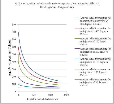
Figure 1. A plot of steady state aquifer radial temperature variation for different fluid injection temperatures.
To test the equations, a model aquifer at a depth typical of supercritical conditions of carbon dioxide storage has been used. For time frames typical of carbon geosequestration projects, steady state temperature fields and stresses are those of thermomechanical concern for the cap rocks. Accordingly, the steady state temperature field of the aquifer was used to deduce that of the cap rock. By using the derived equation that links critical temperature to depth in the cap rock it has been possible to determine the safe temperature required for maintaining the geomechanical integrity of the cap rock to avoid failure in tension and shear. In this work, it has been assumed that the potential aquifer is an open one with quite an appreciable radial extent and permeability such that the injected gas through the entire interval will flow laterally with negligible pressure against the cap rock. In this way stress changes in the cap rock are due only to thermal pressurization of pore fluid which could cause in-situ stress perturbation.
Figure 1 shows the temperature field of the aquifer for different temperatures of fluid injection. Based on the depth to the model aquifer a mean local geothermal gradient of 30 degrees per kilometre the initial ambient temperature of this system is calculated to be 410C using the depth to the
midpoint of the interval. The average initial temperature of the upper cap rock was similarly calculated to be 340C. The
figure shows that for injection temperatures far above the initial ambient temperature the steady state temperatures are far above the systems initial temperature except for injection at 50 and 1000C. The steady state temperature obtained
depends on the carbon dioxide injection temperature. The higher the injection temperature, the larger the exponential drop in the temperature to attain steady state temperature.
Figure 2, which is the most important geomechanically, indicates a plot of the steady state temperature of the cap rock versus depth in the cap rock for a radial temperature of 2.15 meters from the injection well. This location has been selected to determine the effect of heat on the near well bore environment because they are areas that are typically subjected to higher temperatures.
p p
1 sin
1
V
V
p
p5 V 1
C
V
2.124 1
sin 0.35
2.124 1
0
.
25
301
2
.
9
0
.
086
103
9
.
2
35
.
0
1
56
.
246
*
94
.
0
*
2
25
.
0
1
1
D
D
D
T
5 2.124 1 3*8 2.124
C MPa
crD srf th 0.086 103
Figure 2. A plot of steady state temperature versus depth for the cap rock at a radial distance of 2.15 metres from sand face.
The figure shows that during steady state heat transfer a linear relationship exists between temperature and depth in the cap rock interval. The figure also shows a plot of the critical temperature lines for tensile and shear scenarios based on Eqn. (20) and (18). The critical temperatures are seen to be increasing with depth in the cap rock and this is quite consistent with the derivation of the thermal failure criterion because the earth stresses involved are horizontal stresses which increase with depth. The most important observation or finding is that all the injection temperatures except those at 50 and 1000C will result in cap rock tensile
failure. This is due to the fact that the plots for all these temperatures lie above the critical temperature lines for both tensile and shear failures determined by this study except those for 50 and 1000C lines.
The study also shows that as far as this aquifer is concerned an injection temperature of 2000C will be suitable
as far as the upper parts of the cap rock is concerned but failure will occur close to the aquifer interval. One thing consistent about Figure 2 as far as failure in geomechanics is concerned is that it predicts lower failure temperatures for tensile than for shear and that is why the shear failure line lies above the tensile failure. This fact has been established in geomechanics relating where rocks are found to be weaker in tension than in shear8. The potential candidates
for geological repositories for carbon dioxide sequestration include depleted oil and gas reservoirs. Among these reservoirs there are those that were developed using thermal recovery methods that are found to exist at depth typical of supercritical carbon dioxide existence. Most of these were developed using steam or hot water with temperatures above 2000C. Judging from the findings in this study these types of
depleted oil reservoirs must be thoroughly investigated for their intact geomechanical integrity before being considered
as potential geologic repositories worthy of being included in the inventories of geological carbon sinks.
Conclusion
The following inferences are obtained from this work:
1. By virtue of their global availability and promising global carbon storage capacities saline aquifers are top ranked as geological repositories for long term carbon dioxide storage.
2. Under normal circumstances the well head temperature of injected carbon dioxide depends on the source with on-site temperatures being invariably those of ambient ones except in cases where they are maintained at subcritical with regard to temperature to avoid liquefaction in the well bore.
3. The excess heat of direct flue gas could cause thermomechanical problems in saline aquifer cap rock formations which could compromise the anticipated long term hydrodynamic trapping capabilities of these formations.
4. The work presented analytical equations based on thermomechanical related tensile and shear failure criteria which provide a guide to obtaining information about the temperature and pore pressure changes required for tensile and shear failure to occur due to thermal pressurization of pore-fluid in response to high temperature direct flue gas injection.
5. The optimum temperature to inject CO2 is that at or
close to the aquifer temperature and this is the ideal temperature required to maintain cap rock geomechanical integrity.
6. It also serves as a guide to determining the optimum temperature required for injection for all purposes of cap rock integrity due to thermal pressurization problems. In this regard where gas is to be injected from an onsite power plants the temperature does not need to be cooled to that of the aquifer. To reduce cost related to heat exchanger meant for heat extraction from flue gas the temperature can be cooled to near that of the aquifer but commensurate with the geomechanical integrity requirement of the cap rock which in this study is 1500C, 1000C, and 1090C above the aquifer
temperature.
ACKNOWLEDGMENT
Greek Letters
T = total horizontal stress-psi
oh = initial horizontal stress-psi
v= vertical stress-psi
= porosity-fraction = friction angle-degrees
S= thermal expansivity of solid- oK-1
f= thermal expansivity of fluid- oK-1
’h= horizontal effective stress-psi
’v= vertical effective stress-psi
= Poison ratio
References
1Rice, R. G., Do, D. D., Applied Mathematics and Modeling for
Chemical Engineers, John Willey and Sons Inc., 1995.
2Benson, S. M., Cole D., Elements, 2008, 4, 325–331. 3Nguyen, D. N., Allinson, W. G., The Economic of CO
2 Capture
and Geological Storage, (SPE Paper No. 77810) SPE International, 2002.
4Frisch, H. L., J. Phys. Chem., 1957, 6, 93–95.
5Palciauskas, V. V., Domenico, P. A., “Water Resourc. Res.,1982,
18, 281-290.
6Amadu, M., Miadonye, A., Eur. Chem. Bull., 2014, 3, 1047-1054. 7Cogsgroove, J. W., Geol. Soc., Spec. Publ.,1995, 92, 187-196. 8 Aadnoy, B. S., Modern Well Contro., 2nd Ed., CRC Press, 2010. 9https://www.spec2000.net/10-closurestress.
10Eseme, E., Urai, J. L., Krooss, B. M., Littke, R., Oil Shale, 2007,
24, 159-174.
11 Rijken, P., Cook, M., Tectonophysics, 2007, 117-133.
12Lal, M., Shale Stability: Drilling Fluid Interaction and Shale
Strength, (SPE Paper No. 54356) SPE Latin American and Caribbean, 1999.
13http://answers.yahoo.com/question/index?qid=20060926005806
AA9feUJ
14Diane L. J., Mechanical and Acoustical Properties of Sandstones
and Shales, Ph.D. Thesis, Stanford University, 1991.