JEEECCS, Volume 1, Issue 2, pages 21-30, 2015
Predictive maintenance of power industrial
electronic equipment
Şişman George Robert
University POLITEHNICA of Bucharest, Doctoral School of Electronics Communications and Information Technology Faculty Bucharest
Pitesti, Romania [email protected]
Mihai Oproescu
Department of Electronics, Communications and Computers, University of Pitesti
Pitesti, Romania [email protected]
Abstract – The purpose of this article is to present the concepts and equipment which is used in achieving predictive maintenance. Two case studies are presented here. The first shows the concept of maintenance for a single phase inverter based on tree analysis technique. This technique is based on the relation between the symptoms, the causes and the defects for the inverter, but can be extrapolated to another type of electronic equipment as well. The second study presents the equipment for achieving the predictive maintenance for a combination of electrical and electronic equipment. The SIMOCOD software module has the capability to make the on-line diagnosis. The diagnosis module for a 3 phase motor asynchronous is detailed in this study, highlighting the features and advantages in use it.
Keywords: maintenance; 3 phase asynchronous motor; SIMOCOD software.
I. INTRODUCTION
According to European norms of the international IEC or ISO, through maintenance means all technical measures, administrative and management undertaken during the life cycle of the electronic equipment.
Currently exist several techniques for predictive maintenance approach.
Preventive maintenance or proactive maintenance represents preventing damage by planned and scheduled; systematic checks and repairs are performed at predetermined intervals, even when this is clearly necessary. These activities are planned in accordance with manufacturer's instructions and managerial policy aimed at reducing the probability of failure or degradation leading to failure of the work equipment or facilities. Periodic maintenance, planned and carried out correctly is essential for maintaining the safety and reliability of equipment, machinery and working environment helping to eliminate workplace dangers and can prevent sudden and unexpected failure.
The most important typs of preventive maintenance are:
Systematic maintenance or maintenance performed
by a maintenance plan in maintenance activities, current repairs, maintenance and repairs, is constituted in "use and repair plans" [1].
Preventive maintenance and repair system:
- In the form of planned repairs of such revisions (RT), repair of grade 1 (RC1), grade 2 (RC2);
- The shape of periodic checks (Vp), partial revisions (Rp) and overhaul (R);
- By groups of equipment by setting the frequency of interventions.
This typ of maintenance can cause errors in planning the starting of maintenance, it does not take into account the operating hours effective work equipment with a risk that maintenance starts too early (where he worked shortly) or equipment to malfunction before the planned start time maintenance (because it was very intense use).
Predictive maintenance or maintenance performed by comparing the measured parameters with the technological limits of the items / sub-assembly work equipment or facilities, aiming to detect, analyze and correct potential problems before they occur following the interventions of maintenance to be carried out before the occurrence of the defect.
A predictive approach can be applied to any equipment problems if it can measure various parameters like vibration, temperature, pressure, voltage, current, resistance, etc. There must be a limit in terms of technology so that problems can be detected during routine checks. Also, the limit should be set low enough to detect the problem before equipment failure. Correcting the problem is the key route maintenanced.[1] ; [2] ; [3]
The predictive maintenance cycle.
II. STUDYCASEWITHTHEANALYSISOF
THETREETECHNIQUEBASEDONTHE
SYMPTOMS,DEFECTSANDCAUSE
In this study case is presented a technique for make the maintenance predictive based on the tree analysis. To make this type of the analysis is necessary to know the defects, symptoms and causes. This study is applied particular for a single-phase inverter.
Description of the analysis symptoms and causes defects
After a while which is monitored the electronic equipment, a data base with results obtained is created.
starting from the causes to the defects.
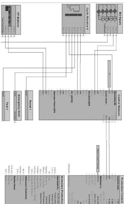
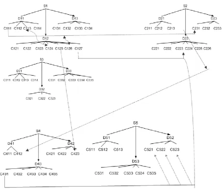
In figure 1, it is presented a tree analysis. The defects, symptoms and causes are interconnected and help to understand the possible causes for damage and to prevent them [5]. After is make the analysis is resulted a table with a possible causes. In according with the table is created a software program in the PLC (Programmable Logic Controller). The PLC is able alone to take a decision when is detected one of the error which is declared in the soft. This error is detected with tree analysis.
Figure 1. Diagram of the tree analysis with defects, symptoms and causes
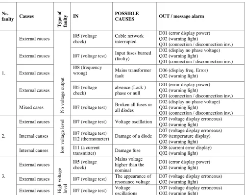
In Table 1 it is presented an interconnection of the defects - causes in the structure of the PLC system. Also in the input of the PLC are connected the sensor who perform the check of the parameter and on the output is the message and the action who is realized after the sensor is made the checks. So, for each sensor is assigned a input on the PLC, which is interconnected with one output.
Checking is done within the limits set. These limits are set by operator after he consults the tree analysis.
Nr.
faulty Causes
T yp e of fau lt
y IN POSSIBLE
CAUSES OUT / message alarm
1. External causes No volt age output I05 (voltage check) Cable network interrupted
D01 (error display power) Q02 (warning light)
Q01 (connection / disconnection inv.)
External causes I07 (voltage test) Input fuses burned (faulty)
D02 (display no phase voltage) Q02 (warning light)
Q01 (connection / disconnection inv.)
External causes
I08 (frequency
wrong) Mains transformer
fault
D06 (display freq. Error) Q02 (warning light)
External causes I05 (voltage check)
absence (Lack ) phase or null
D01 (error display power) Q02 (warning light)
Q01 (connection / disconnection inv.)
Mixed cases I07 (voltage test) Broken all fuses or all diodes
D02 (display no phase voltage) Q02 (warning light)
Q01 (connection / disconnection inv.)
2. External causes low volt age leve
l I07 (voltage test) Voltage oscillation D07 (voltage display erroneous) Q02 (warning light)
Internal causes I07 (voltage test)
I12 (thermometer) Damage of a diode
D07 (voltage display erroneous) D09 (temperature display) Q02 (warning light)
Internal causes I11 (a current
transmitter) Damage fuse
D08 (current error display) Q02 (warning light)
3. External causes High volt age leve l I05 (voltage check) Mains voltage higher than the nominal
D01 (error display power) Q02 (warning light)
External causes I07 (voltage test) The appearance of resonance voltage
D07 (voltage display erroneous) Q02 (warning light)
External causes I07 (voltage test) Voltage oscillations
D07 (voltage display erroneous) Q02 (warning light)
Table 1. Structure of the tree analysis using the PLC
III. STUDY CASE FOR PREDICTIVE MAINTENANCE BASED ON EQUIPMENT TYPE SIMOCOD WITH DIAGNOSTIC AND MONITORING MANAGEMENT
INCLUDED
Using the equipment for predictive maintenance has enjoyed an increased lately, although currently the technology is too expensive, and the installation process can be lengthy.
The case study for diagnostic a motor three - phase asynchronous has been used a SIMOCOD module. The data recorded in this module is acquired using several sensors such as: sensors for temperature, inductive sensors, monitoring electrical phase.
To identify the defects it must needed to monitor a lot of parameters. The monitored parameters for a three-phase asynchronous motor are: - Monitoring temperature of the motor;
- Partial discharge monitoring; - Noise and vibration of the motor;
- Monitoring the speed and torque of the motor; - Monitoring the absence of voltage at the terminal of motor;
- Monitoring the trends of the all 3 phase of the motor.
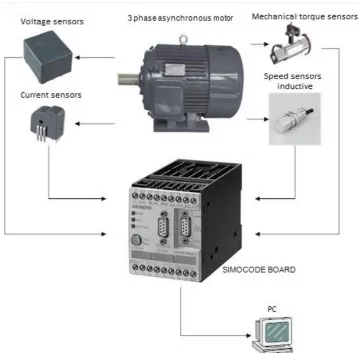
In Figure 2 is presented a block diagram of diagnostics for an electric motor using a SIMOCOD module. This scheme includes sensors for speed, torque, power and inductive with which it acquires data from motor. These data are transmitted to SIMOCOD module using the communication protocol PROFIBUS, Ethernet or IO-Link.
Figure 2. Diagnostic block diagram of a DC motor with permanent magnets with a module SIMOCOD
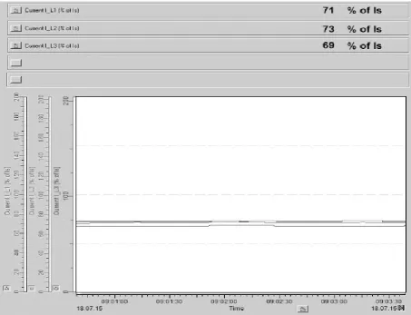
The purpose of using this application is the prevention the damages of the components by setting certain operating parameters of the electrical motor. The monitoring of the work regime of a motor three-phase can be done using the interface presented in figure 4.
Figure 3. Basic System with a SIMOCOD module [7]
The monitoring of the work regime of a motor three-phase can be done using an interface presented in figure 4. This monitoring is for all 3 phase of the motor. If exist some imbalance in amplitude are signaled immediately because has exceeded their limits. This monitoring it is realizing on-line. These techniques are monitoring the motor in time and prevent a possible fault of the motor.
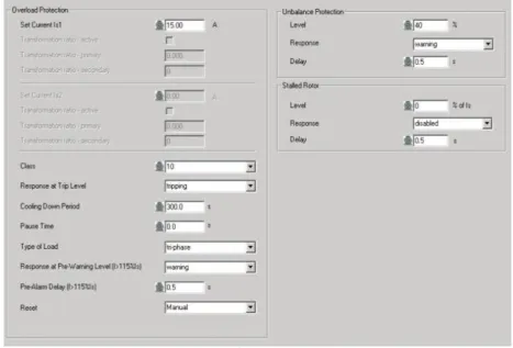
To achieve prevention in the case of an electric motor, the SIMOCODE allows settings a limit for operation. These settings are set in an interface presented in figure 5.
This module has the possibility to set the following settings:
- The maximum current of the stator;
- Temperature range at which the engine to stop;
- The emergence imbalance between phases (the limit that is allowed without affecting the smooth functioning of the motor);
- The number of operating hours; - number of starts of the motor;
- Starting the motor type - star – triangle; - Speed of the motor and the ramp for
Figure 4. Interface for monitoring the amplitude of all 3 phase for a electrical motor
Figura 5. Interface to set the operating parameters of a three-phase motor
The software at the SIMOCOD allow create a page for monitored continuously the vital functions and parameter. These parameters and functions are introduced in maintenance page. This page for maintenance is presented in figure 6.
To prevent a possible damage for an electric motor is created a interface which established a lot of protection for the motor such as:
- Change status of the motor (ON, OFF, slow, fast);
- Set the currents limits for all 3 phase and set the maximum current;
- The maximum voltage for each phase; - Set the operation time;
- Set the working temperature depending the motor type;
- Set the time required cooling after overheating the motor.
Figure 6. Interface for maintenance
Figure 7. Setting page for protection the electric motor
To prevent the damage to other components when the motor is damaged the SIMOCOD module have possibility to create a page for initialization. This page for initialization the motor make an interrogation
Figure 8. Page for initialization
Another advantage to use the SIMOCOD module for predictive maintenance is represented the speed process for parameterizing.
The process it is very fast because it is possible to copy and transfer in the same directory. It is possible to copy the parameters at a old motors and put the same parameters at a new motors.
The memory of the SIMOCOD is structured on the module.
Figure 9. Parameterizing process [7]
A logical program is needed to be created when the SIMOCOD module is used in the maintenance predictive process. The schematic block language is used for an easy diagnostic.
In figure 10 is presented a diagram block for software using in process for maintenance predictive. These diagram contains blocks for command or
decision, in the left side is presented the input block in the center are the blocks for control, protection and in the right part is the decision block and the output blocks, communication blocks and the block for indicator lights for alarms.
In block for enhanced protection is presented the value limits for operating and also is show if this value is in range or not. In the software configuration is exist the possibility to enter a block which is connected to the control block, that can turn off the motor when one of the parameters set is out of set range, all these action for protect the electrical motor.
Also when is detects one alarm, the interconnection line between connection the input block (signal from the sensor measure of current), control block and the extended protection becomes red as is illustrated in figure 11.
At the same time on the display is showing an error message with short description of the defects. In the control block is set a parameter for stop the motor if the alarm have a high importance.
operations in different sectors, including the industry, and is applied in all kinds of environments.
The maintenance is essential to ensure the continuity of production to manufacture high quality products and maintain the company's competitiveness, the impact on health, and safety at work.
In the last years, the diagnostic techniques for monitoring the process, in order to apply the advanced predictive maintenance techniques based on electronic equipment, were moved from the traditional methods to Artificial Intelligence techniques, which use Neural Networks and Fuzzy Logic Systems.
It is increasingly recognized that most techniques based on artificial intelligence have, besides the advantages, certain drawbacks. Thus, a hybrid approach of the diagnosis is better to be used.
The main contribution of this paper is the comparative design of diagnostics interfaces into various programs dedicated (such as PC - S7 and SIMOCOD) to highlight the differences in monitoring and signaling of the faults. The user interface contains various parameters in the settings page, including the limits in on-line operation and diagnosis of the electronic equipment.
It can be noted that the both methods has clearly advantages in prolonging the service life for the electronic devices monitored, even if both use only traditional maintenance methods. A comparative analysis between traditional and advanced maintenance methods will be realized in next paper.
A. Abbreviations and Acronyms
PLC - Programmable Logic Controller FB – Function Block
PDM – predictive maintenance RP – partial revision
RC1/ RC 2 – repair of grade 1 or 2 R – general revision - overhaul
WORK UNDER PHD STAGES, CONTRACT NUMBERS: SD04/46 AND SD04/04.
THE WORK HAS BEEN FUNDED BY THE SECTORAL OPERATIONAL PROGRAMME HUMAN RESOURCES DEVELOPMENT 2007-2013 OF THE MINISTRY OF EUROPEAN FUNDS THROUGH THE FINANCIAL AGREEMENT POSDRU187/1.5/S/155420.
SOME FIGURES, TABLES AND TEXT ARE
REPRODUCED FROM ICTPE PAPER CODE
01PES29HEREWITHKINDPERMISSIONFROM
THE ICTPE – 2015 GENERAL CHAIR [SEPTEMBER,2015].
REFERENCES
[1] Wikipedia : Predictive Maintenance.
[2] Adolf Crespo Marquez, The Maintenance Management
Framework, Models and Methods for Complex System Maintenance.
[3] K.S. Jardine_, Daming Lin, Dragan Banjevic., A review on
machinery diagnostics and prognostics implementing condition-based maintenance, Department of Mechanical and Industrial Engineering, University of Toronto, 5 King’s College Road Toronto, Ont., Canada M5S 3G8.
[4] Giraud L, La Maintenance. Etat de la connaissance et etude
exploratoire. Publication IRSST –Canada 2008.
[5] N. Bizon, M. Oproescu, 2007, Power converters used in
energy generation systems (in Romanian language: Convertoare de Putere utilizate in Sistemele de Generare a Energiei), Publishing House of the University of Pitesti, Piteşti, ISBN 978-973-690-644-2.
[6] Sisman George Robert, 2015, Models predictive and
corrective maintenance - an overview, the first PhD report.
[7] Siemens –SIMOCOD reinterpretation of the manual
[8] F. Zidani, D. Diallo, M. E. H. Benbouzid, and R. N. Said. A fuzzy-based approach for the diagnosis of fault modes in a voltage-fed PWM inverter induction motor drive. IEEE Transactions on Industrial Electronics, Vol. 55, No. 2, Pages: 586-593,2008.
[9] G.R. Sisman, M. Oproescu. Predictive maintenance at
![Figure 9. Parameterizing process [7]](https://thumb-us.123doks.com/thumbv2/123dok_us/7807477.2085377/7.595.89.548.58.400/figure-parameterizing-process.webp)