7th International Symposium
on Leveraging Applications of Formal Methods, Verification
and Validation
-Doctoral Symposium, 2016
Handling Domain Knowledge in Design and Analysis of Design Models
Kahina Hacid and Yamine Ait-Ameur
21 pages
Guest Editors: Anna-Lena Lamprecht
Handling Domain Knowledge in Design and Analysis of Design
Models
Kahina Hacid1and Yamine Ait-Ameur2
1kahina.hacid@enseeiht.fr,2yamine@enseeiht.fr Universit´e de Toulouse ; INP ; IRIT
Institut de Recherche en Informatique de Toulouse - France
Abstract: The development of complex systems involves several domain experts and several design models corresponding to different analyses (views) of the same system. No explicit information regarding the characteristics of the performed sys-tem analyses is given. We propose a stepwise approach to keep trace of the process that allows a system designer to build a point of view first, by explicitly defining the features of an analysis (view) and second, by explicitly defining the required con-cepts and properties borrowed from a design model. The objective is to trigger a given model analysis. Strengthening the design models with domain knowledge is highly recommended before performing such analysis. We propose a model anno-tation methodology for this purpose. These approaches are deployed using Model Driven Engineering (MDE) techniques and illustrated on an didactic case study.
Keywords: multi-view modeling, domain knowledge, ontologies, design model, model analysis
1
Introduction
Usually, during the development of complex systems several models corresponding to different views of the same system are built. In most of the developments, there is no explicit information regarding the characteristics of the performed system analyses.
Thus, our work is motivated by the following observations. First, the system developer usually uses part of the system model for a specific activity (an analysis to perform on the model). Indeed, some concepts are not useful for a given analysis. For example, real-time analysis does not require all the functional concepts of the analyzed system. There is no explicit definition of the concepts of a given model required by a given model analysis. Second, when performing model analysis, the system developer does not explicitly describe the analysis that he/she used. In order to take design decision, another system developer needs the whole information and hypotheses related to the realized system model analyses ( in fact, the result of an analysis may interfere with the inputs and results of another analysis. Thus information regarding the used method, tool, properties for an analysis may be needed to best evaluate its corresponding output result.). The system developer needs to know for example: what are the performed model analyses (tool, method, inputs, outputs, etc.)? What are the hypotheses made by the other analyses? And what are the parts of the system that have been analyzed?
a given model analysis. All these definitions are described in a model we will denote as point of view. Proceeding this way, our approach keeps trace of the process that allows a system designer to build its model analysis.
The achievement of the objectives of our proposal requires to make explicit all the knowledge and information (like the required properties, the configuration details to perform an analysis, the used method analysis, the analysis results, etc.) manipulated by the system developer while performing the analyses. This knowledge is formalized within domain ontologies. Thus, we propose a model annotation methodology in order to make explicit references to this domain knowledge carried out by domain ontologies. The model annotation methodology is also used as a preliminary step in order to strengthen and enrich system design models.
This paper is structured as follows. Section 2 presents a didactic case study illustrating our approach. Section 3 gives a definition of domain ontologies and design models. Our global ap-proach and the developed methodology for strengthening models through an annotation-based method are described in section 4. Then, our methodology to handle multi-analysis of systems is presented in section 5. Section 6 details the implementation of our approach on the basis of Model Driven Engineering (MDE) techniques. The application of the proposed global approach on the case study is shown in section 7. Finally, section 8 overviews different approaches pro-moting multi-view modeling of systems. A conclusion ends this paper and identifies some future research directions.
2
A case study
In order to illustrate our proposal, we have borrowed the case study used in [HA]. It is a didac-tic case study describing a simple information system corresponding to a given specification. It deals with the management of students within the European higher education system. This sys-tem offers two kind of curricula: the Licence (or bachelor), Master, Doctorate curricula (LMD for short) and the Engineer curricula. In the LMD curricula, each of the three proposed diplomas corresponds to a specific level of education : Bachelor/Licence (high school degree with 180 credits), Master (Bachelor with 120 credits) and PhD (Master with 180 credits). In the Engi-neering curricula, an engiEngi-neering degree is delivered after at least five years of studies within specialized high engineering institutes.
In the studied information system, students register to prepare their next expected diploma. This registration action takes into account the last hold academic degree (or last diploma) as a pre-requisite to register for the next diploma. A set of defined constraints on this information system does not allow a student to register for a diploma if he/she does not have the necessary background qualifications. For example, Phd degree registration is authorized only if the last held degree corresponds to a Master degree. The studied information system prescribes the necessary conditions (constraints) for registering students for preparing diplomas.
3
Background
3.1 Ontologies
Gruber defines an ontology asan explicit specification of a conceptualization[Gru93]. We con-sider a domain ontology as aformal and consensual dictionary of categories and properties of entities of a domain and the relationships that hold among them[JPA06]. By entity we mean being, i.e, any concept that can be said to be in the domain. The term dictionary emphasizes that any entity of the ontology and any kind of domain relationship described in the domain ontology may be referenced by a symbol directly (usually referenced to asURI), for any purpose and from any context, independently of other entities or relationships. This identification symbol may be either a language independent identifier, or a language-specific set of words. But, whatever this symbol is, and unlike linguistic dictionaries, this symbol denotes directly a domain entity or re-lationship, thedescriptionof which is formallystated providing for (automatic) reasoning and consistency checking. Finally, the ontology conceptualization is agreed upon by a community larger than the members involved in one particular application development. For instance, ISO 13584-compliant (PLIB) [ISO98, ISO04] product ontologies follow a formal standardization process and are published as ISO or IEC international standards.
3.2 Design models
Design models target the definition of models from which systems are realized. They are de-scribed within design languages. They represent abstractions of the system to be designed and/or analyzed. When models are defined and according to the modeling language, it becomes possi-ble to perform a set of analyses like verification, validation, simulation, etc. The choice of the modeling language has an impact on the kind of analysis that can be performed on the models defined within this language.
During design processes, several models of the same system may be produced within differ-ent modeling languages. Indeed, some modeling languages focus on some specific aspects on which analyses become possible. This situation leads to heterogeneous models and heteroge-neous modeling corresponding to specific views of the system under design.
4
An overview of our global approach: Domain knowledge
han-dling in design and multi-analysis of models
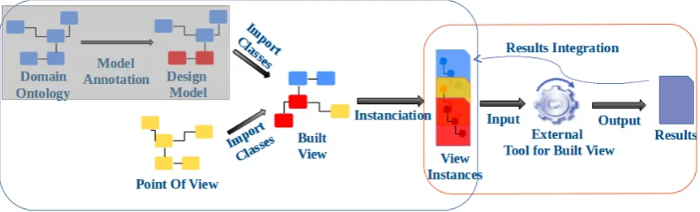
the quality of the system design model (by adding new domain properties and constraints). Thus, the model analysis methodology will be triggered on the new enriched design model (output of the model annotation step) and the quality of the obtained views will be increased. The model analysis approach is addressed in section6.
Once the integration of the two defined parts is made, the obtained view models are automat-ically instantiated, the corresponding analysis are triggered on the view instances (instances of the obtained view) and the results (output of external analysis tool) are collected.
Our global approach uses Model Driven Engineering (MDE) techniques and all the imple-mented models conform to the Ecore meta-model.
Figure 1: General framework for design and analysis of design models.
5
Annotating design models with references to ontologies
In this section, we describe the work we have done in order to strengthen system design models [HA16,HA]. It is represented on the left hand side of Figure1(grey box).
Usually, design models do not handle, in an explicit manner, the knowledge of the application domain or context where models are designed. Therefore, some useful properties available in the domain knowledge are not considered by the design models. Moreover, these properties may be violated by the design model if they were handled. An error or an inconsistency in the model is produced in this case.
Hence, linking knowledge domains expressed by ontologies with the design models strength-ens the designed models and offers the support of more verifications, since the properties ex-pressed in the ontologies will become part of the designed models. Model annotation is the mechanism we set up to link ontologies with design models. It consists in defining specific relationships between ontology concepts and model entities.
5.1 A methodology to handle design model enrichment
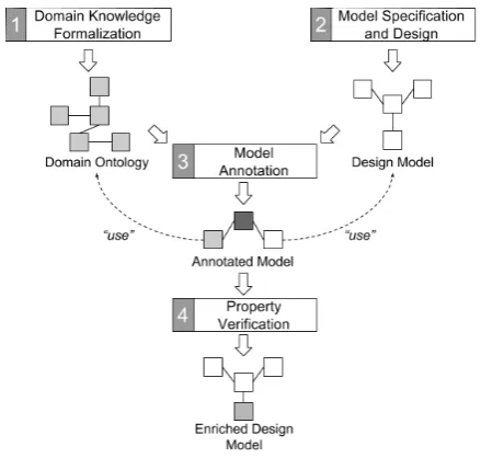
Figure 2: A Generic approach for Model annotation.
1. Domain Knowledge Formalization. This step consists in formalizing the knowledge of a specific domain within domain ontologies. These ontologies fulfil all the requirements recalled in subsection3.1.
2. Model specification and design. Design models formalizing and handling a given set of re-quirements are defined at this step. They are formalized within a specific modeling lan-guage and support different analyses offered by the chosen modeling lanlan-guage.
3. Model Annotation. This step defines annotations through explicit references to ontologies. In other words, models make explicit references to ontologies concepts. Different kinds of annotations have been identified. The explicit definition and details on the types of annotation are given in [HA,HA16].
4. Properties Verification. This step requires (re-)checking of the properties of the design mod-els after annotation. Indeed, some already checked properties may no longer be valid and/or new properties mined from the ontologies through annotation may appear explic-itly (i.e. the ontological entities - properties, concepts or constraints - involved in the annotation process are integrated in the new enriched design model at the end of step 3 and become available in it).
Ontology modeling
Figure 3: TheEquivalenceRelationship.
∀x,y,z|x7→y∈Eq∧y7→z ∈Eq
⇒ x7→z∈Eq
EQ_transitivity: Equivalence.allInstances()-> forAll(eq1, eq2| eq1.right = eq2.left implies Equivalence.allInstances()-> exists(eq3|eq2.right = eq3.right and eq1.left = eq3.left));
Figure 4: Equivalence relationship: Transitivity property expressed OCL.
constraints. The whole ontological relationships like Equivalence, restriction, etc. are also ex-pressed. As illustration, figure3gives the definition of the equivalence relationship as a class at the meta-modeling level.
The properties related tosymmetry, reflexivity and transitivityof the equivalence relationship are formalized as OCL constraints. For example, Figure4gives an overview of the formalization of transitivity property.
Core classes for model annotation
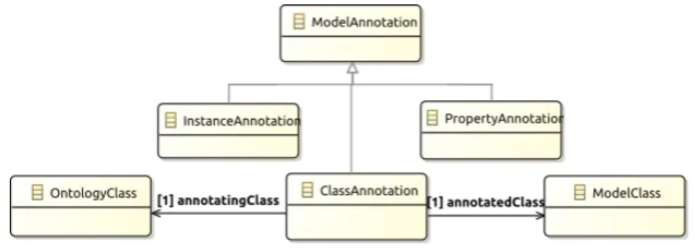
The relevant information and entities required to set up the methodology depicted in Figure2are summarized in a simplified class diagram on Figure5.
In step 3 of the model annotation approach (Figure2) relations defining the annotation model are established between the design model entities and the ontology concepts. These annotation relationships link between design model entities (classes, properties, datatypes, associations, etc. ) and ontology concepts (classes, properties, associations, etc.).
Figure5depicts an extract of the annotation meta-model where the annotation relationships are formalized. The annotation classClassAnnotationis defined to link (annotate) a design model class (ex. ModelClass) with an explicit reference to an ontology concept (ex. OntologyClass). Other types of annotation classes, likeInstanceAnnotationandPropertyAnnotation, etc. are also defined. They are used to annotate other entities of the design model (instances, properties, etc.).
Some remarks
The languages used to model ontologies, design models and annotation relationships may differ. Semantic alignment between these modeling languages may be required. This topic is out of the scope of this paper, we consider that these languages have the same ground semantics. A single and shared modeling language for the description of both ontologies, design models and anno-tations is used in this work. Furthermore, the engineering application we studied uses modeling languages with classical semantics using closed world assumption (CWA) [AM16].
The annotation step (step 3) described above requires the definition of annotation mechanisms. Different kinds of annotation mechanisms can be set up (inheritance, partial inheritance and al-gebraic relationships) [HA,HA16]. The details and choice of the right mechanism are also out of the scope of this paper.
6
Handling multi-analyses of systems: our proposal
We have developed a stepwise methodology to handle multi-analyses of systems and/or system model processing. The definition of this methodology comes from the observation of several experiments conducted by system developers (in order to formalize well established development practices and processes). It is based on making explicit the knowledge related to the know-how associated to the performed analysis.
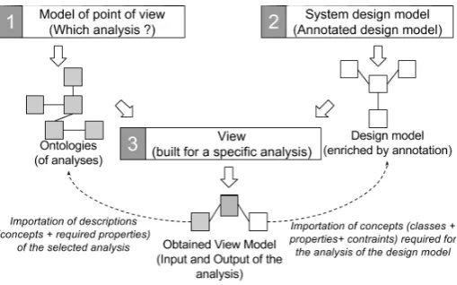
Figure 6 below depicts the defined methodology. This triptych describes what a system or model analysis is. We have identified three steps detailed in the following.
Figure 6: A generic approach for multi-view modeling.
method used for a given analysis. It shall also organize these analyses with respect to the kind or type of analysis.
2. System design model. This step consists of the definition of the model of the system to be analyzed. The choice of the right abstraction level is a key point. Indeed, if the chosen abstraction level leads to models that do not contain or represent the resources required by the analysis then the chosen analysis cannot be performed. Our methodology is able to check this feasibility condition.
3. View. The integration of both the point of view (analysis description) obtained at Step 1 and the system model obtained at Step 2 is performed at the final Step 3. Here, the view corresponding to the definition of the analysis (point of view of Step 1) on the system model (obtained at Step 2) is built. Checking the availability of all the information required by the analysis is done at this level i.e. checking the feasibility of the analysis.
At the end of this process we obtain a specific view model corresponding to the defined anal-ysis description. Instances of the view model are generated and the external tool in charge of the specific analysis (and described within the point of view) is triggered on this set of instances.
Finally, notice that although the above defined methodology relies on the definition of an integration point of view (step 1) and system design model (step 2), these two models are defined independently in an asynchronous manner. Second, note that the presented multi-view analyses methodology uses a single and shared modeling language for the description of the three involved models (point of view, design model and view model).
6.1 The core model elements
The relevant information and concepts required to set up the methodology depicted in Figure6
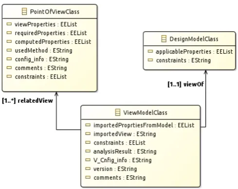
are summarized in a simplified class diagram on Figure7. The following relevant properties are required in order to obtain the integrated view corresponding to a system model analysis.
1. Model of point of view. ThePointOfViewClasscorresponds to the description of an analysis defined at step 1 of Figure6. The following properties are defined.
• TheviewProperties property is associated to the view. it characterize the descriptive properties of an analysis.
• The requiredProperties property defines the set of properties of the system model needed in order to trigger the described analysis. Mappings may be required to map the properties defined in the point of view with those defined in the system model.
• ThecomputedPropertiesproperty describes the output of the analysis corresponding to the currently described point of view or analysis.
• The usedMethod property defines the specific technique, method or program that supports the defined analysis.
Figure 7: Core classes for multi-view modeling
2. System design model. It corresponds to the information model to describe the models to be analyzed (step 2 of Figure6). It is formalized within a modeling language that supports different analyses. We may find at least what follows.
• TheapplicablePropertiesproperty corresponds to the properties associated to classes of the model to be analyzed.
• Theconstraintsproperty corresponds to the constraints that are defined on the model to be analyzed. These constraints characterize the correct set of instances.
3. View. Finally, at step 3 of the approach (Figure6), the integrated view or analysis is built by composing the resources issued from both concepts of step 1 and step 2.
• TheimportedPropertiesFromModelproperty corresponds to the set of properties im-ported from the model to be analyzed. It defines the properties needed from the model to build the view and perform the analysis.
• TheimportedView property refers to the analysis to be performed on the considered model.
• The constraints property defines the new constraints that apply on the integrated view.
• TheanalysisResultproperty defines the property containing the results of the analy-sis.
This meta-model also defines the constraints that guarantee the correct integration. The correct correspondence betweenapplicablePropertiesof the design model and therequiredPropertiesof the point of view can be checked in order to guarantee the correct construction of the view. Thus, a construction is considered correct only if all the required properties (requiredProperties) can be retrieved within the defined design model properties (applicableProperties). These proper-ties correspondences are made possible through the explicit references to ontologies. In fact, if two properties refer to the sameuriof an ontological property, then they are considered to be semantically equivalent (identical).
7
Developed prototype
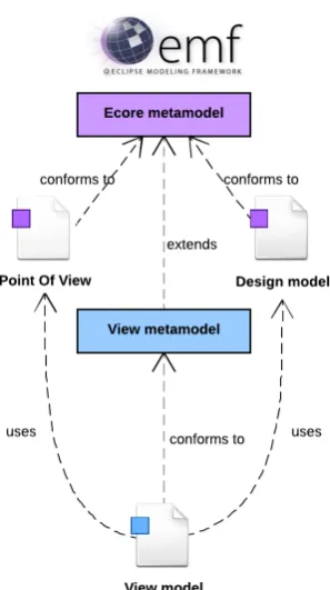
Figure 8: Implementation of the solution with Eclipse EMF.
infrastructures. Models are built in a modular manner with referencing capabilities between models. This modularity allows a developer to use EMF with other Eclipse projects.
Among the used projects in our developments, we mention the Sirius[sir] project related to the development of graphical tool/editors. Sirius is an Eclipse project which allows the creation of model-based workbench by leveraging the Eclipse Modeling technologies, including EMF and GMF[sir]. Sirius has been used in this work in order to support the whole graphical tool development we have set up as prototype.
Model to model transformation is set up in our prototype. This is amany to onetransformation which takes a point of view and a design model as input and returns a specific view model (corresponding to the integration of the two input models) as output.
Figure8 describes the overall architecture of our implementation. The view meta-model is defined and the editors for the construction of a specific analysis view are generated. The view meta-model is implemented as an extension of the Ecore meta-model. The design model and the point of view are described within Ecore and conform to the Ecore meta-model. The trans-formations required for the construction of a specific view and its instances are implemented in Java.
Details about the implementation of the model annotation methodology can be found in [HA16,
AH17]
8
Application on the
student information system
case study
The deployment of our approach, presented in section4, on thestudent information systemCase study (presented in section2) is described in this section.
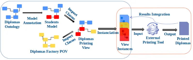
Figure 9: General workflow of thestudent information system.
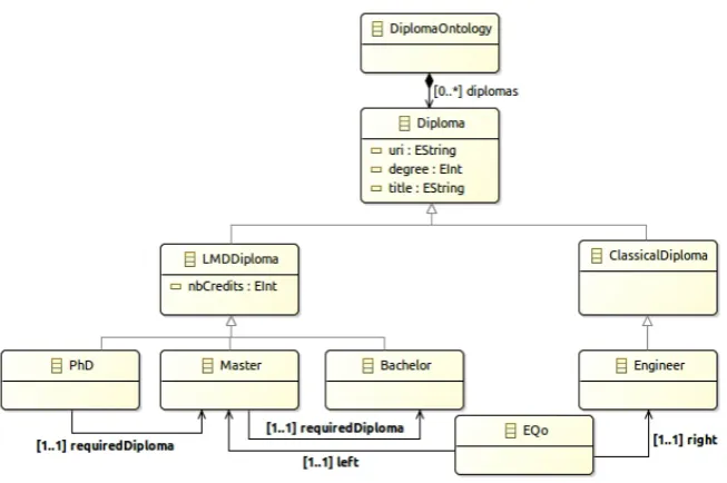
Figure 10: TheDiplomasontology.
At the end of the procedure we obtain a set of required instances (instances of the obtained diploma factory view) to trigger the external printing tool in charge of printing the students diplomas (or any other function/tool that uses properties of a given point of view and of the system under design)
8.1 Strengtheningstudent information systemmodel
The application of the model annotation methodology on thestudent information systemcase study has been already presented in our previous work [HA]. Next, we show the end-to-end application of our global approach.
8.1.1 Step 1. Domain knowledge formalization
The defined ontology for diplomas is depicted in Figure10in a simple class diagram. diplomas ontologycontains a set of inter-related classes and relevant properties as follows.
- A subsumption relationship (represented by theis a relationship - or inheritance relation-ship - on Figure10) is used to define hierarchies between categories of diplomas.LMDDiploma andClassicalDiplomadescribe respectively theBachelor, MasterandPhDdiplomas and other diplomas (e.g.Engineer).
property is represented by anequivalentclass (EQo) linkingMasterandEngineer classes of the same ontology.
- A constraint, defined as thesisRequirement, carried by the requiredDiploma relationship is added to assert that any master (or any equivalent diploma) is required to prepare a PhD.
Note that the presented diplomas ontology is only one of the possible ontologies for describing the diplomas domain knowledge. A final domain ontology needs to be consensually defined.
8.1.2 Step 2. Model specification and design
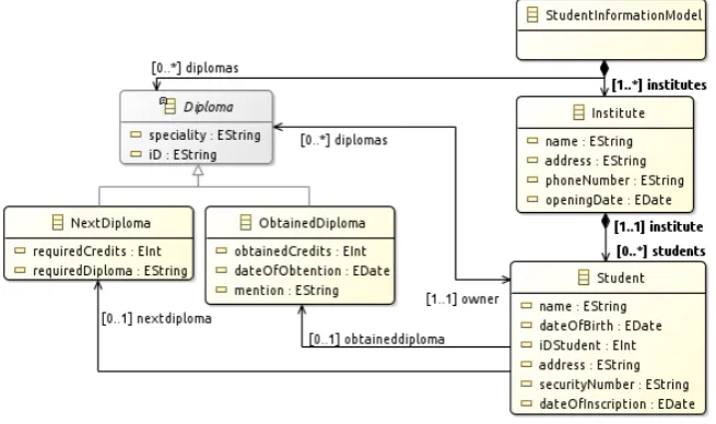
The system’s design model is defined according to a given specification. Figure11shows one possible UML class diagram representing the metamodel of the information system related to the management of students and their diplomas. It is composed of institutes and diplomas. An institute (a university or an engineering school) is composed of its students. In this model, a student is represented byStudentclass with thename,dateOfBirth,iDStudent(for student num-ber), address,securityNumber (for social security number) anddateOfRegistrationproperties. Each student is related to his/herinstituteand his/herDiplomas. Moreover, eachStudentholds anObtainedDiplomarepresenting the last obtained diploma (obtainedDiplomarelationship) and aNextDiplomareferring to the next in preparation diploma (nextDiplomarelationship). An in-stitute is represented by the Institute Class with properties name, adress, phoneNumber and openingDate. TheObtainedDiplomais characterised by thedateOfObtention(for date when the diploma was obtained by a student) and theobtainedCredits(for the number of credits a student obtained for his last diploma) properties. nextDiplomais characterised by the requiredCredits andrequiredDiploma(for the number of credits and the grade of diploma required in order to register for a specific next diploma) properties.
⇒
Student.obtainedDiploma.iD = ”m” self.obtainedDiploma.iD = ’m’
Figure 12: Formalization ofphdInscritpionconstraint.
Figure 13: Annotation of Student model.
Moreover, a constraint namedphdInscriptionon the studentnextDiplomais defined. It asserts that a student registering for a PhD diploma needs to hold a master diploma to be allowed to register for a PhD. It represents a model invariant and it is defined by the OCL constraint of Figure12.
8.1.3 Step 3. Model annotation
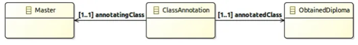
In step 3, the annotation model is defined. Figure13 shows how the annotation relationships between the design model entities and the ontology concepts are set up. TheObtainedDiploma class of thestudents information systemdesign model instantiates ModelClass (Figure 3) and theMasterclass of thediplomas ontologyinstantiatesOntologylClass(Figure 3). The Obtained-Diplomaclass is annotated by making explicit references to theMasterclass using a ClassAn-notation class. Similarly, NextDiploma is annotated by PhD of the diplomas ontology. The non-structural equivalence property and thethesisRequirementconstraint can now be accessed and exploited. Thus, the equivalence between Master and Engineer classes is expressed and made explicit within the design model.
8.1.4 Step 4. Properties verification
Student.nextDiploma.iD=”P” ⇒
annotation(Student.obtainedDiploma) ∈eq(Master)
phdInscritpion: self.nextDiploma.iD = ’p’ implies
let c: ecore::EClass = ClassAnnotation.allInstances()-> select(inst|inst.annotatedClass =
self.obtainedDiploma)-> at(0).annotatingClass in Equivalence.allInstances()-> exists(eq|
eq.left.uri = ’Master_uri’ and eq.right = c);
Figure 14: The OCL constraintphdInscritpionafter annotation.
Figure 15:Student information systemmodel instance.
are defined. Next subsections show how thediplomas factory analysis is performed on these model and its instances.
8.2 Thediploma factorymodel analysis
The details of the construction and application of thediploma factoryanalysis are given in the following subsections.
8.2.1 Step 1. Model of point of view: Thediploma factoryanalysis
The deployment of our model analysis methodology requires, in its first step, the description of a point of view. To make this description explicit, we have used a simple class diagram to express the different properties required to perform the analysis.
The defined point of view for the diploma factory analysis is depicted in Figure 16. The external printing functionto be triggered and its required input parameters are described. The printingMethodproperty characterises the externalprinting functionto be used and the printing-Toolproperty makes references to the external tool (encoding the printing function) that will be called for printing students diplomas.
are defined as view properties and are directly imported from the corresponding ontologies. The Resultclass defining theurlproperty is used to store the output results of theprinting function.
Notice that the semantics of these properties (required properties and view ones) are defined in the corresponding domain ontologies (diplomas ontology, students ontology, printing ontology, etc.), they are not given here due to space limitation. Moreover, not all the design model proper-ties are required for the construction of adiploma factoryview, thus only the required properties, specified within the point of view model, are imported for each specific analysis.
Figure 16: Thediplomas factorypoint of view.
8.2.2 Step 2. System design model
The design model some system analyses or functional computation of the properties of the sys-tem under design is defined at this level. It corresponds, in this case study, to the new strength-enedstudent information systemmodel and its instances obtained at the end of themodel anno-tationstep (subsection8.1.4).
8.2.3 Step 3.Diplomas factoryview
A specific diplomas factory view can be built by integrating the resources issued from both thestudent information system model and thediplomas factorypoint of view. Thus, both the required propertiesand theview propertiesare imported in thediplomas factoryview. Figure17
depicts thediplomas factoryview.
Figure 18:Diplomas factoryview instance.
- TheStudent,ObtainedDiploma,Institute,PrintingPoVandResultclasses containing the dif-ferent properties referenced by the point of view of thediplomas factoryanalysis (Figure
16) are imported (note that by selecting a point of view in the view editor, all the referenced properties, with their classes, are automatically imported in the view).
- The instances corresponding to these classes and properties are generated by a model to model transformation.
- An instance of theResultclass is generated for each instance of the Diplomas factory view, it contains theurl(address) of the output of the external tool to trigger. In this case the location of each printed diploma can be accessed.
Figure18depicts such a diplomas factory view instance. It is built (extracted) from the enriched student information system model instance shown in Figure15. Only the relevant information fordiplomas factoryview are defined.
- The instances of therequired propertiesdefined withinStudent,ObtainedDiplomaand Insti-tuteclasses are imported.
- The instance ofNextDiplomaclass is not imported in the view instance since it is not relevant for this view (not described within thediplomas factorypoint of view).
- TheusedMethod,usedToolproperties are instantiated to describe the suited analysis to trigger on the view instances.
- The view properties like paperSizeare instantiated. The additional user choices are made explicit.
At the end, the external printing tool is triggered on the set of diplomas factory instances. Students diplomas are printed and their corresponding storingurlare given as output results of the printing tool.
logical properties can envelope any system analysis. This is our intent when using a function that borrows information both from the point of view and from the design model. In the particular case of our paper, the proposed design model in the case study formalizes the student information system knowledge and the printing process is not directly attached to this knowledge. However, some of the knowledge formalized in the student information system model is required in order to trigger the printing. Thus, the printing process is defined as a specific view of the system and does not unnecessarily overload the system design model
9
Related work
Many researchers studied the issue of multi-view modeling. Sirius [sir] is part of EMF. It pro-poses a multi-view approach which allows users to manipulate sub-parts of a model and focus on specific view of a design model. [KAK09] presents the RAM approach, an aspect-oriented mod-eling approach that provides scalable multi-view modmod-eling and however faces the global view consistency challenge. It focuses on the composition of UML class diagrams, UML state and sequence diagrams. [TQB+14] deals with the integration of viewpoints (points of view) in the development of mechatronic products. The vocabulary, assumption and constraints of a specific domain are defined inViewpoint contractsanddependency models(shared models) are used to capture the existing relations between the different views of a system.
[SKSP10] propose a framework for multi-view modeling to support Embedded systems Engi-neering. A common shared model, that consists of a combination of relevant knowledge from the domain-specific views, is defined in SysML. The domain-specific views are directly generated from this common model which makes extensive use of SysML profiles and model transforma-tions. [Ver94] discuss the requirements for multi-view modeling and several approaches and tools are compared with regards to the defined requirements.
[FKG91] present an approach based software development with multiple viewpoints. View-point templates are used to encapsulate the style (representation) and the workplan (specification method) corresponding to the different domain views of a system. Aviewpointframework, cor-responding to the developed approach, and a logic-based approach to consistency handling are proposed later in [FGH+94]. To the best of our knowledge, it is the only approach that focusses on the importance of the explicit definition of a point of view.
10
Conclusion and perspectives
The work presented in this paper shows the major interests of model strengthening and mutli-view model analyses.
The first part of our work demonstrated that the use of domain ontologies to describe the shared knowledge of a domain and the capability to link the design system models to these on-tologies through annotations allows system designers to handle properties, axioms, hypotheses and theorems directly mined from the application domain and thus, allows the system designers to design higher quality models. Indeed, the quality of design models is increased by the an-notation operation. As a consequence, properties and constraints available in the ontology are imported in the annotated model. Checking whether these properties and constraints are fulfilled may reveal some inconsistencies in the design models that shall be fixed by the system developer. The second contribution of our work concerns the capability to handle model analyses. This idea is not new. But, the novelty of our approach consists in two main aspects. The first one consists in making explicit model analyses through the definition of a descriptive model (point of view) that describes the whole features of an analysis. Ontologies of model analysis are used for this purpose. The second aspect concerns the explicit definition of the required concepts and properties borrowed from a design model to trigger a given model analysis. Indeed, as for annotation, when performing a model analysis, our approach keeps trace of the process that allowed a system designer to build its model analysis.
We have shown the deployment of our global approach in the case of model driven engineering techniques. We have shown on a case study, the feasibility of our approach from model strength-ening - using model annotation methodology - to multi-view model analysis methodology. A deployment on formal methods based on proof and refinement using the Event-B method is also made [HA]. The formal deployment of multi-view model analysis methodology is however still under progress.
The work presented in this paper has been developed as part of the AME Corac-Panda project [ame] and has been applied to several case studies issued from embedded systems engineering domain. Experiments with MDE based techniques have been conducted on avionic systems [AH15,AH17].
Several other research directions to pursue our work can be envisaged. We are interested in offering the capability to integrate and ideally compose several model analyses. For the mo-ment, the developed approach allows a designer to perform a single analysis at a time. Allowing such integration will offer different analysis patterns. Finally, we only considered, in this pa-per, the case where the different involved models (ontologies, design models, analysis models) are described in the same modeling language, the case of semantic mismatch, where ontologies, design models and points of view are not described in the same modeling language, should be considered.
Bibliography
[AH17] Y. A¨ıt Ameur, K. Hacid. Report AME Corac-Panda project. Technical report, Institut de Recherche en Informatique de Toulouse, Toulouse university, 2017.
[AM16] Y. A¨ıt Ameur, D. M´ery. Making explicit domain knowledge in formal system devel-opment.Science of Computer Programming121, 2016.
[ame] AME-CORAC: Avionique Modulaire Etendue COnseil pour la Recherche Aronau-tique Civile.http://aerorecherchecorac.com/.
[emf] Eclipse Modeling Framework.https://www.eclipse.org/modeling/emf/.
[FGH+94] A. C. Finkelstein, D. Gabbay, A. Hunter, J. Kramer, B. Nuseibeh. Inconsistency han-dling in multiperspective specifications.IEEE Transactions on Software Engineering 20(8):569–578, 1994.
[FKG91] A. Finkelstein, J. Kramer, M. Goedicke. Viewpoint oriented software development. University of London, Imperial College of Science and Technology, Department of Computing, 1991.
[Gru93] T. R. Gruber. A Translation Approach to Portable Ontology Specifications.Knowl. Acquis.5(2), June 1993.
[HA] K. Hacid, Y. A¨ıt Ameur. Strengthening MDE and Formal Design Models by Refer-ences to Domain Ontologies. A Model Annotation Based Approach. InLeveraging Applications of Formal Methods, Verification and Validation: Foundational Tech-niques - 7th International Symposium, ISoLA 2016, Proceedings, Part I.
[HA16] K. Hacid, Y. A¨ıt Ameur. Annotation of Engineering Models by References to Do-main Ontologies. In Model and Data Engineering - 6th International Conference, MEDI 2016, Almer´ıa, Spain, September 21-23, 2016, Proceedings. Pp. 234–244. 2016.
[ISO98] ISO. Industrial automation systems and integration - Parts library - Part 42: Descrip-tion methodology: Methodology for structuring parts families. Iso ISO13584-42, International Organization for Standardization, Geneva, Switzerland, 1998.
[ISO04] ISO. Industrial automation systems and integration - Parts library - Part 25: Logi-cal resource: LogiLogi-cal model of supplier library with aggregate values and explicit content. Iso ISO13584-25, International Organization for Standardization, Geneva, Switzerland, 2004.
[JPA06] S. Jean, G. Pierra, Y. A¨ıt Ameur. Domain Ontologies: A Database-Oriented Anal-ysis. In Filipe et al. (eds.), WEBIST (Selected Papers). Lecture Notes in Business Information Processing 1. Springer, 2006.
[sir] Sirius.http://www.eclipse.org/sirius/.
[SKSP10] A. A. Shah, A. A. Kerzhner, D. Schaefer, C. J. J. Paredis.Multi-view Modeling to Support Embedded Systems Engineering in SysML. Pp. 580–601. Springer Berlin Heidelberg, Berlin, Heidelberg, 2010.
[TQB+14] M. T¨orngren, A. Qamar, M. Biehl, F. Loiret, J. El-Khoury. Integrating viewpoints in the development of mechatronic products.Mechatronics24(7):745–762, 2014.