MPLS Basic Configuration Guide, Cisco IOS XE 16 (Cisco ASR 900
Series)
First Published:2017-05-04 Last Modified:2019-08-01
Americas Headquarters
Cisco Systems, Inc.170 West Tasman Drive San Jose, CA 95134-1706 USA
http://www.cisco.com Tel: 408 526-4000
800 553-NETS (6387) Fax: 408 527-0883
THE SPECIFICATIONS AND INFORMATION REGARDING THE PRODUCTS IN THIS MANUAL ARE SUBJECT TO CHANGE WITHOUT NOTICE. ALL STATEMENTS, INFORMATION, AND RECOMMENDATIONS IN THIS MANUAL ARE BELIEVED TO BE ACCURATE BUT ARE PRESENTED WITHOUT WARRANTY OF ANY KIND, EXPRESS OR IMPLIED. USERS MUST TAKE FULL RESPONSIBILITY FOR THEIR APPLICATION OF ANY PRODUCTS.
THE SOFTWARE LICENSE AND LIMITED WARRANTY FOR THE ACCOMPANYING PRODUCT ARE SET FORTH IN THE INFORMATION PACKET THAT SHIPPED WITH THE PRODUCT AND ARE INCORPORATED HEREIN BY THIS REFERENCE. IF YOU ARE UNABLE TO LOCATE THE SOFTWARE LICENSE OR LIMITED WARRANTY, CONTACT YOUR CISCO REPRESENTATIVE FOR A COPY.
The Cisco implementation of TCP header compression is an adaptation of a program developed by the University of California, Berkeley (UCB) as part of UCB's public domain version of the UNIX operating system. All rights reserved. Copyright©1981, Regents of the University of California.
NOTWITHSTANDING ANY OTHER WARRANTY HEREIN, ALL DOCUMENT FILES AND SOFTWARE OF THESE SUPPLIERS ARE PROVIDED “AS IS" WITH ALL FAULTS. CISCO AND THE ABOVE-NAMED SUPPLIERS DISCLAIM ALL WARRANTIES, EXPRESSED OR IMPLIED, INCLUDING, WITHOUT LIMITATION, THOSE OF
MERCHANTABILITY, FITNESS FOR A PARTICULAR PURPOSE AND NONINFRINGEMENT OR ARISING FROM A COURSE OF DEALING, USAGE, OR TRADE PRACTICE. IN NO EVENT SHALL CISCO OR ITS SUPPLIERS BE LIABLE FOR ANY INDIRECT, SPECIAL, CONSEQUENTIAL, OR INCIDENTAL DAMAGES, INCLUDING, WITHOUT LIMITATION, LOST PROFITS OR LOSS OR DAMAGE TO DATA ARISING OUT OF THE USE OR INABILITY TO USE THIS MANUAL, EVEN IF CISCO OR ITS SUPPLIERS HAVE BEEN ADVISED OF THE POSSIBILITY OF SUCH DAMAGES.
Any Internet Protocol (IP) addresses and phone numbers used in this document are not intended to be actual addresses and phone numbers. Any examples, command display output, network topology diagrams, and other figures included in the document are shown for illustrative purposes only. Any use of actual IP addresses or phone numbers in illustrative content is unintentional and coincidental.
All printed copies and duplicate soft copies of this document are considered uncontrolled. See the current online version for the latest version. Cisco has more than 200 offices worldwide. Addresses and phone numbers are listed on the Cisco website at www.cisco.com/go/offices.
Cisco and the Cisco logo are trademarks or registered trademarks of Cisco and/or its affiliates in the U.S. and other countries. To view a list of Cisco trademarks, go to this URL:www.cisco.com go trademarks. Third-party trademarks mentioned are the property of their respective owners. The use of the word partner does not imply a partnership relationship between Cisco and any other company. (1721R)
C O N T E N T S
Multiprotocol Label Switching (MPLS) on Cisco Routers 1
C H A P T E R 1
Finding Feature Information 1
Information About MPLS 1
MPLS Overview 1
Functional Description of MPLS 2
Label Switching Functions 2
Distribution of Label Bindings 2
Benefits of MPLS 3
How to Configure MPLS 4
Configuring a Router for MPLS Switching 4
Verifying Configuration of MPLS Switching 5
Configuring a Router for MPLS Forwarding 5
Verifying Configuration of MPLS Forwarding 6
Additional References 7
Feature Information for MPLS on Cisco Routers 8
Glossary 8
MPLS Transport Profile 11
C H A P T E R 2
Restrictions for MPLS-TP on the Cisco ASR 900 Series Routers 11
Information About MPLS-TP 12
How MPLS Transport Profile Works 12
MPLS-TP Path Protection 12
Bidirectional LSPs 12
MPLS Transport Profile Static and Dynamic Multisegment Pseudowires 13
MPLS-TP OAM Status for Static and Dynamic Multisegment Pseudowires 13
Tunnel Midpoints 13
MPLS-TP Linear Protection with PSC Support 14
MPLS-TP Linear Protection with PSC Support Overview 14
Interoperability With Proprietary Lockout 15
Mapping and Priority of emlockout 16
WTR Synchronization 17
Priority of Inputs 18
PSC Syslogs 18
How to Configure MPLS Transport Profile 18
Configuring the MPLS Label Range 18
Configuring the Router ID and Global ID 19
Configuring Bidirectional Forwarding Detection Templates 20
Configuring Pseudowire OAM Attributes 21
Configuring the Pseudowire Class 22
Configuring the Pseudowire 24
Configuring the MPLS-TP Tunnel 25
Configuring MPLS-TP LSPs at Midpoints 28
Configuring MPLS-TP Links and Physical Interfaces 29
Configuring MPLS-TP Linear Protection with PSC Support 30
Configuring Static-to-Static Multisegment Pseudowires for MPLS-TP 33
Configuring Static-to-Dynamic Multisegment Pseudowires for MPLS-TP 34
Configuring a Template with Pseudowire Type-Length-Value Parameters 37
Verifying the MPLS-TP Configuration 38
Configuration Examples for MPLS Transport Profile 38
Example: Configuring MPLS-TP Linear Protection with PSC Support 38
Example: Verifying MPLS-TP Linear Protection with PSC Support 39
Example: Troubleshooting MPLS-TP Linear Protection with PSC Support 39
MPLS Multilink PPP Support 41
C H A P T E R 3
Prerequisites for MPLS Multilink PPP Support 41
Restrictions for MPLS Multilink PPP Support 41
Information About MPLS Multilink PPP Support 42
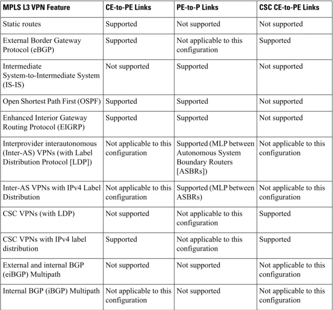
MPLS Layer 3 Virtual Private Network Features Supported for Multilink PPP 42
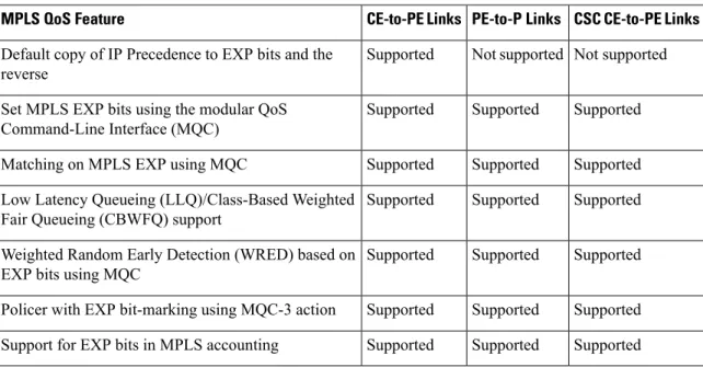
MPLS Quality of Service Features Supported for Multilink PPP 43
MPLS Multilink PPP Support and PE-to-CE Links 43
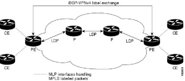
MPLS Multilink PPP Support and Core Links 44
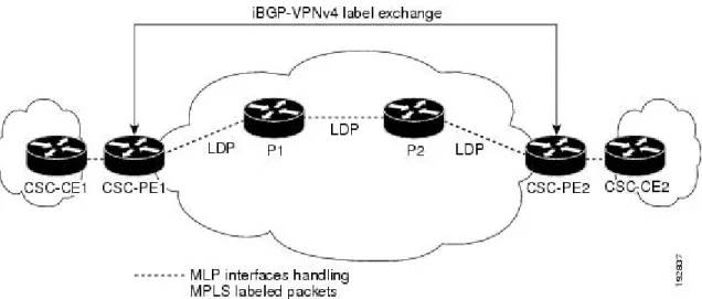
MPLS Multilink PPP Support in a CSC Network 45
MPLS Multilink PPP Support in an Interautonomous System 46
How to Configure MPLS Multilink PPP Support 46
Creating a Multilink Bundle 46
Assigning an Interface to a Multilink Bundle 48
Verifying the Multilink PPP Configuration 51
Configuration Examples for MPLS Multilink PPP Support 54
Sample MPLS Multilink PPP Support Configurations 54
Example: Configuring Multilink PPP on an MPLS CSC PE Device 54
Example: Creating a Multilink Bundle 56
Example: Assigning an Interface to a Multilink Bundle 56
MPLS LSP Ping, Traceroute, and AToM VCCV 57
C H A P T E R 4
Prerequisites for MPLS LSP Ping, Traceroute, and AToM VCCV 57
Restrictions for MPLS LSP Ping, Traceroute, and AToM VCCV 58
Information About MPLS LSP Ping, Traceroute, and AToM VCCV 58
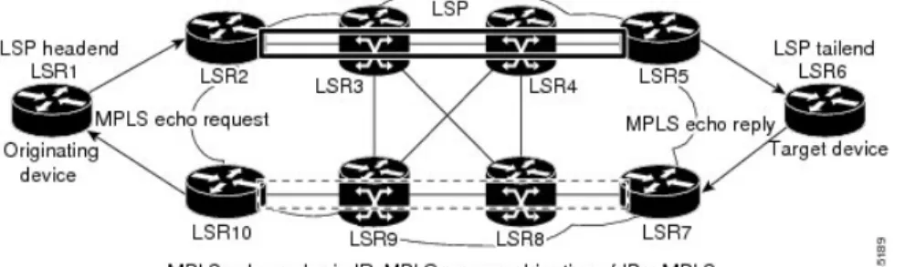
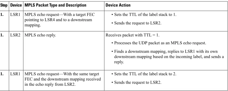
MPLS LSP Ping Operation 58
MPLS LSP Traceroute Operation 60
Any Transport over MPLS Virtual Circuit Connection Verification 62
AToM VCCV Signaling 63
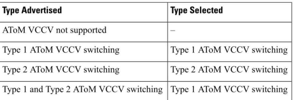
Selection of AToM VCCV Switching Types 63
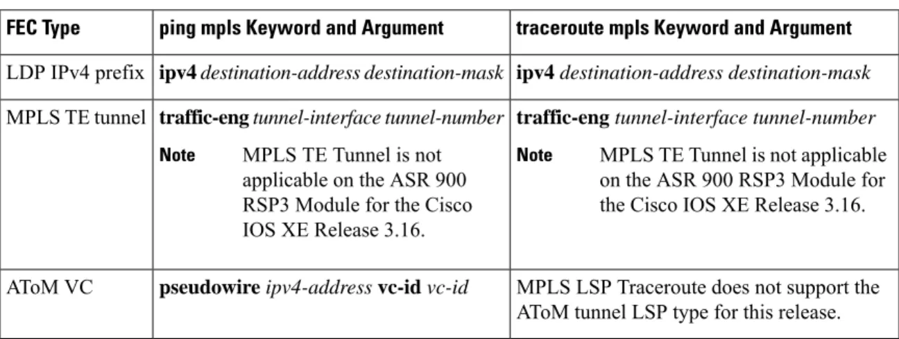
Command Options for ping mpls and trace mpls 64
Selection of FECs for Validation 64
Reply Mode Options for MPLS LSP Ping and Traceroute 65
Reply Mode Options for MPLS LSP Ping and Traceroute 66
Other MPLS LSP Ping and Traceroute Command Options 68
Option Interactions and Loops 70
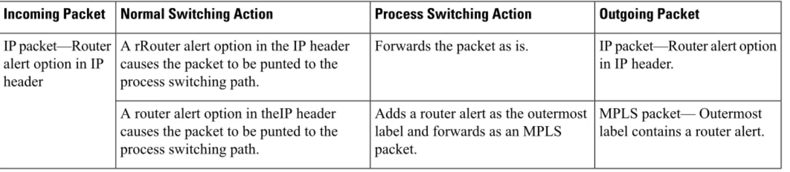
MPLS Echo Request Packets Not Forwarded by IP 73
Information Provided by the Device Processing LSP Ping or LSP Traceroute 74
MTU Discovery in an LSP 75
LSP Network Management 76
ICMP ping and trace Commands and Troubleshooting 77
MPLS LSP Ping and Traceroute Discovers LSP Breakage 77
MPLS LSP Traceroute Tracks Untagged Cases 85
MPLS LSP Ping and Traceroute Returns a Q 87
Load Balancing for IPv4 LDP LSPs 88
NSR LDP Support 91
C H A P T E R 5
Finding Feature Information 91
Prerequisites for NSR LDP Support 91
Information About NSR LDP Support 92
Roles of the Standby Route Processor and Standby LDP 92
LDP Operating States 93
Initial State 93
Steady State 93
Post Switchover 93
Supported NSR Scenarios 94
How to Configure NSR LDP Support 94
Enabling NSR LDP Support 94
Troubleshooting Tips for NSR LDP Support 95
Configuration Examples for NSR LDP Support 95
Example: NSR LDP Configuration 95
Additional References for NSR LDP Support 96
Feature Information for NSR LDP Support 97
Flex LSP Overview 99
C H A P T E R 6
Signaling Methods and Object Association for Flex LSPs 99
Associated Bidirectional Non Co-routed and Co-routed LSPs 100
Restrictions for Flex LSP 101
Restrictions for Non Co-routed Inter-Area Flex LSP Tunnels 102
How to Configure Co-routed Flex LSPs 102
Configuring Co-routed Flex LSPs 103
Verifying the Co-routed Flex LSP Configuration 104
How to Configure Non Co-routed Inter-area Flex LSP Tunnels 105
Configuring OSFP for Non Co-routed Flex LSP 107
Verifying the Non Co-routed Inter-area Flex LSP Tunnels
Troubleshooting Flex LSP 109
Flex LSP Phase 2 113
Flex LSP SRLG and Exclude Option for Explicit Path 114
Configuring Flex LSP SRLG and Exclude Option 114
Verifying the Flex LSP SRLG and Exclude Option 115
Flex LSP Non-Revertive 1:1 Path Protection 116
Configuring Flex LSP Non-Revertive Path Protection 116
Verifying Flex LSP Non-Revertive Path Protection 117
Flex LSP Sticky 119
Configuring Flex LSP Sticky Option 121
Verifying the Flex LSP Sticky Option 121
Flex LSP Hop Count and Cost-Max Limit 123
Flex LSP Cost-Max Limit 124
Configuring Flex LSP Hop Count and Cost-Max Limit 124
Verifying Flex LSP Hop Count and Cost-Max Limit 125
Flex LSP ECMP min-fill, max-fill, random 125
Configuring Flex LSP ECMP min-fill and max-fill 126
Verifying the Flex LSP ECMP min-fill and max-fill 127
Restore Path Option 128
Configuring the Restore Path Option 128
Verifying the Restore Path Option 128
C H A P T E R
1
Multiprotocol Label Switching (MPLS) on Cisco
Routers
This document describes commands for configuring and monitoring Multiprotocol Label Switching (MPLS) functionality on Cisco routers and switches. This document is a companion to other feature modules describing other MPLS applications.
•Finding Feature Information, on page 1 •Information About MPLS, on page 1 •How to Configure MPLS, on page 4 •Additional References, on page 7
•Feature Information for MPLS on Cisco Routers, on page 8 •Glossary, on page 8
Finding Feature Information
Your software release may not support all the features documented in this module. For the latest caveats and feature information, seeBug Search Tooland the release notes for your platform and software release. To find information about the features documented in this module, and to see a list of the releases in which each feature is supported, see the feature information table.
Use Cisco Feature Navigator to find information about platform support and Cisco software image support. To access Cisco Feature Navigator, go towww.cisco.com/go/cfn. An account on Cisco.com is not required.
Information About MPLS
MPLS Overview
Multiprotocol label switching (MPLS) combines the performance and capabilities of Layer 2 (data link layer) switching with the proven scalability of Layer 3 (network layer) routing. MPLS enables service providers to meet the challenges of explosive growth in network utilization while providing the opportunity to differentiate services without sacrificing the existing network infrastructure. The MPLS architecture is flexible and can be employed in any combination of Layer 2 technologies. MPLS support is offered for all Layer 3 protocols, and scaling is possible well beyond that typically offered in today’s networks.
MPLS efficiently enables the delivery of IP services over an ATM switched network. MPLS supports the creation of different routes between a source and a destination on a purely router-based Internet backbone. By incorporating MPLS into their network architecture, service providers can save money, increase revenue and productivity, provide differentiated services, and gain competitive advantages.
Functional Description of MPLS
Label switching is a high-performance packet forwarding technology that integrates the performance and traffic management capabilities of data link layer (Layer 2) switching with the scalability, flexibility, and performance of network layer (Layer 3) routing.
Label Switching Functions
In conventional Layer 3 forwarding mechanisms, as a packet traverses the network, each router extracts all the information relevant to forwarding the packet from the Layer 3 header. This information is then used as an index for a routing table lookup to determine the next hop for the packet.
In the most common case, the only relevant field in the header is the destination address field, but in some cases, other header fields might also be relevant. As a result, the header analysis must be done independently at each router through which the packet passes. In addition, a complicated table lookup must also be done at each router.
In label switching, the analysis of the Layer 3 header is done only once. The Layer 3 header is then mapped into a fixed length, unstructured value called alabel.
Many different headers can map to the same label, as long as those headers always result in the same choice of next hop. In effect, a label represents aforwarding equivalence class--that is, a set of packets which, however different they may be, are indistinguishable by the forwarding function.
The initial choice of a label need not be based exclusively on the contents of the Layer 3 packet header; for example, forwarding decisions at subsequent hops can also be based on routing policy.
Once a label is assigned, a short label header is added at the front of the Layer 3 packet. This header is carried across the network as part of the packet. At subsequent hops through each MPLS router in the network, labels are swapped and forwarding decisions are made by means of MPLS forwarding table lookup for the label carried in the packet header. Hence, the packet header does not need to be reevaluated during packet transit through the network. Because the label is of fixed length and unstructured, the MPLS forwarding table lookup process is both straightforward and fast.
Distribution of Label Bindings
Each label switching router (LSR) in the network makes an independent, local decision to determine a label value to represent a forwarding equivalence class. This association is known as a label binding. Each LSR informs its neighbors of the label bindings it has made.
When a labeled packet is being sent from LSR A to the neighboring LSR B, the label value carried by the IP packet is the label value that LSR B assigned to represent the forwarding equivalence class of the packet. Thus, the label value changes as the IP packet traverses the network.
The awareness of label bindings by neighbouring routers is facilitated using the following protocols: • Label Distribution Protocol (LDP) - Enables peer LSRs in an MPLS network to exchange label binding
information for supporting hop-by-hop forwarding in an MPLS network.
Multiprotocol Label Switching (MPLS) on Cisco Routers Functional Description of MPLS
• Tag Distribution Protocol (TDP) - Supports MPLS forwarding along normally routed paths. • Resource Reservation Protocol (RSVP) - Supports MPLS traffic engineering.
• Border Gateway Protocol (BGP) - Supports MPLS virtual private networks (VPNs) .
Benefits of MPLS
MPLS provides the following major benefits to service provider networks:
Scalable support for Virtual Private Networks (VPNs)--MPLS enables VPN services to be supported in service provider networks, thereby greatly accelerating Internet growth.
The use of MPLS for VPNs provides an attractive alternative to the building of VPNs by means of either ATM or Frame Relay permanent virtual circuits (PVCs) or various forms of tunneling to interconnect routers at customer sites.
Unlike the PVC VPN model, the MPLS VPN model is highly scalable and can accommodate increasing numbers of sites and customers. The MPLS VPN model also supports “any-to-any” communication among VPN sites without requiring a full mesh of PVCs or the backhauling (suboptimal routing) of traffic across the service provider network. For each MPLS VPN user, the service provider’s network appears to function as a private IP backbone over which the user can reach other sites within the VPN organization, but not the sites of any other VPN organization.
From a user perspective, the MPLS VPN model enables network routing to be dramatically simplified. For example, rather than having to manage routing over a topologically complex virtual backbone composed of many PVCs, an MPLS VPN user can generally employ the service provider’s backbone as the default route in communicating with all of the other VPN sites.
Explicit routing capabilities (also called constraint-based routing or traffic engineering)--Explicit routing employs “constraint-based routing,” in which the path for a traffic flow is the shortest path that meets the resource requirements (constraints) of the traffic flow.
In MPLS traffic engineering, factors such as bandwidth requirements, media requirements, and the priority of one traffic flow versus another can be taken into account. These traffic engineering capabilities enable the administrator of a service provider network to
• Control traffic flow in the network • Reduce congestion in the network • Make best use of network resources
Thus, the network administrator can specify the amount of traffic expected to flow between various points in the network (thereby establishing a traffic matrix), while relying on the routing system to
• Calculate the best paths for network traffic • Set up the explicit paths to carry the traffic
Support for IP routing on ATM switches (also called IP and ATM integration)--MPLS enables an ATM switch to perform virtually all of the functions of an IP router. This capability of an ATM switch stems from the fact that the MPLS forwarding paradigm, namely, label swapping, is exactly the same as the forwarding paradigm provided by ATM switch hardware.
Multiprotocol Label Switching (MPLS) on Cisco Routers
The key difference between a conventional ATM switch and an ATM label switch is the control software used by the latter to establish its virtual channel identifier (VCI) table entries. An ATM label switch uses IP routing protocols and the Tag Distribution Protocol (TDP) to establish VCI table entries.
An ATM label switch can function as a conventional ATM switch. In this dual mode, the ATM switch resources (such as VCI space and bandwidth) are partitioned between the MPLS control plane and the ATM control plane. The MPLS control plane provides IP-based services, while the ATM control plane supports ATM-oriented functions, such as circuit emulation or PVC services.
How to Configure MPLS
This section explains how to perform the basic configuration required to prepare a router for MPLS switching and forwarding.
Configuration tasks for other MPLS applications are described in the feature module documentation for the application.
Configuring a Router for MPLS Switching
MPLS switching on Cisco routers requires that Cisco Express Forwarding be enabled.
For more information about Cisco Express Forwarding commands, see the Cisco IOS Switching Command Reference.
SUMMARY STEPS
1. enable
2. configure terminal
3. ip cef distributed
DETAILED STEPS
Purpose Command or Action
Enables privileged EXEC mode.
enable
Step 1
Example: • Enter your password if prompted.
Device> enable
Enters global configuration mode.
configure terminal
Example: Step 2
Device# configure terminal
Enables Cisco Express Forwarding on the route processor card.
ip cef distributed
Example: Step 3
Device(config)# ip cef distributed
Multiprotocol Label Switching (MPLS) on Cisco Routers How to Configure MPLS
Verifying Configuration of MPLS Switching
To verify that Cisco Express Forwarding has been configured properly, issue theshow ip cef summary
command, which generates output similar to that shown below: SUMMARY STEPS
1. show ip cef summary
DETAILED STEPS
show ip cef summary
Example:
Router# show ip cef summary
IP CEF with switching (Table Version 49), flags=0x0 43 routes, 0 resolve, 0 unresolved (0 old, 0 new)
43 leaves, 49 nodes, 56756 bytes, 45 inserts, 2 invalidations 2 load sharing elements, 672 bytes, 2 references
1 CEF resets, 4 revisions of existing leaves 4 in-place modifications
refcounts: 7241 leaf, 7218 node Adjacency Table has 18 adjacencies Router#
Configuring a Router for MPLS Forwarding
MPLS forwarding on Cisco routers requires that forwarding of IPv4 packets be enabled.
For more information about MPLS forwarding commands, see theMultiprotocol Label Switching Command Reference.
SUMMARY STEPS
1. enable
2. configure terminal
3. interface type slot/subslot /port[. subinterface]
4. mpls ip
5. end
DETAILED STEPS
Purpose Command or Action
Enables privileged EXEC mode.
enable
Step 1
Example: • Enter your password if prompted.
Device> enable
Multiprotocol Label Switching (MPLS) on Cisco Routers
Purpose Command or Action
Enters global configuration mode.
configure terminal
Example: Step 2
Device# configure terminal
Specifies the Gigabit Ethernet interface and enters interface configuration mode.
interface type slot/subslot /port[. subinterface] Example:
Step 3
Device(config)# interface gigabitethernet 4/0/0
Enables MPLS forwarding of IPv4 packets along normally routed paths for the Gigabit Ethernet interface.
mpls ip
Example: Step 4
Device(config-if)# mpls ip
Exits interface configuration mode and returns to privileged EXEC mode.
end
Example: Step 5
Device(config-if)# end
What to do next
Configure either of the following:
• MPLS Label Distribution Protocol (LDP). For information about configuring MPLS LDP, see theMPLS Label Distribution Protocol Configuration Guide.
• Static labels. For information about configuring static labels, seeMPLS Static Labels.
Verifying Configuration of MPLS Forwarding
To verify that MPLS forwarding has been configured properly, issue theshow mpls interfaces detailcommand, which generates output similar to that shown below:
SUMMARY STEPS
1. show mpls interfaces detail
DETAILED STEPS
show mpls interfaces detail
Example:
Device# show mpls interfaces detail
Interface GigabitEthernet1/0/0:
Multiprotocol Label Switching (MPLS) on Cisco Routers Verifying Configuration of MPLS Forwarding
LSP Tunnel labeling not enabled MPLS operational
MTU = 1500 Interface POS2/0/0:
IP labeling enabled (ldp) LSP Tunnel labeling not enabled MPLS not operational
MTU = 4470
Additional References
Related Documents
Document Title Related Topic
Cisco IOS Master Commands List, All Releases
Cisco IOS commands
Cisco IOS Multiprotocol Label Switching Command Reference
MPLS commands
Standards
Title Standard
--The supported standards applicable to the MPLS applications appear in the respective feature module for the application.
MIBs
MIBs Link MIB
To locate and download MIBs for selected platforms, Cisco software releases, and feature sets, use Cisco MIB Locator found at the following URL:
http://www.cisco.com/go/mibs The supported MIBs applicable to the MPLS
applications appear in the respective feature module for the application.
RFCs
Title RFC
--The supported RFCs applicable to the MPLS applications appear in the respective feature module for the application.
Multiprotocol Label Switching (MPLS) on Cisco Routers
Technical Assistance
Link Description
Support & Downloads
The Cisco Support and Documentation website provides online resources to download documentation, software, and tools. Use these resources to install and configure the software and to troubleshoot and resolve technical issues with Cisco products and technologies. Access to most tools on the Cisco Support and Documentation website requires a Cisco.com user ID and password.
Feature Information for MPLS on Cisco Routers
The following table provides release information about the feature or features described in this module. This table lists only the software release that introduced support for a given feature in a given software release train. Unless noted otherwise, subsequent releases of that software release train also support that feature. Use Cisco Feature Navigator to find information about platform support and Cisco software image support. To access Cisco Feature Navigator, go towww.cisco.com/go/cfn. An account on Cisco.com is not required.
Table 1: Feature Information for MPLS on Cisco Routers
Feature Information Releases
Feature Name
Multiprotocol label switching (MPLS) combines the performance and capabilities of Layer 2 (data link layer) switching with the proven scalability of Layer 3 (network layer) routing. MPLS enables service providers to meet the challenges of explosive growth in network utilization while providing the opportunity to differentiate services without sacrificing the existing network infrastructure.
In Cisco IOS XE Release 2.1, this feature was introduced.
In Cisco IOS XE Release 3.5S, support was added for the Cisco ASR 903 Router.
The following commands were introduced or modified:interface atm,
mpls atm control-vc,mpls atm vpi,mpls ip(global configuration),
mpls ip(interface configuration),mpls ip default-route,mpls ip propagate-ttl,mpls ip ttl-expiration pop,mpls label range,mpls mtu,
show mpls forwarding-table,show mpls interfaces,show mpls label range,debug mpls adjacency,debug mpls events,debug mpls lfib cef,debug mpls lfib enc,debug mpls lfib lsp,debug mpls lfib state,
debug mpls lfib struct,debug mpls packets. Cisco IOS XE
Release 2.1 Cisco IOS XE Release 3.5S MPLS
(Multiprotocol Label
Switching)
Glossary
BGP--Border Gateway Protocol. The predominant interdomain routing protocol used in IP networks.
Border Gateway Protocol--See BGP.
Multiprotocol Label Switching (MPLS) on Cisco Routers Feature Information for MPLS on Cisco Routers
FIB--Forwarding Information Base. A table that contains a copy of the forwarding information in the IP routing table.
Forwarding Information Base--See FIB.
label--A short, fixed-length identifier that tells switching nodes how the data (packets or cells) should be forwarded.
label binding--An association between a label and a set of packets, which can be advertised to neighbors so that a label switched path can be established.
Label Distribution Protocol--See LDP.
Label Forwarding Information Base--See LFIB.
label imposition--The act of putting the first label on a packet.
label switching router--See LSR.
LDP--Label Distribution Protocol. The protocol that supports MPLS hop-by-hop forwarding by distributing bindings between labels and network prefixes.
LFIB--Label Forwarding Information Base. A data structure in which destinations and incoming labels are associated with outgoing interfaces and labels.
LSR--label switching router. A Layer 3 router that forwards a packet based on the value of an identifier encapsulated in the packet.
MPLS--Multiprotocol Label Switching. An industry standard on which label switching is based.
MPLS hop-by-hop forwarding--The forwarding of packets along normally routed paths using MPLS forwarding mechanisms.
Multiprotocol Label Switching--See MPLS.
Resource Reservation Protocol--See RSVP.
RIB--Routing Information Base. A common database containing all the routing protocols running on a router.
Routing Information Base--See RIB.
RSVP--Resource Reservation Protocol. A protocol for reserving network resources to provide quality of service guarantees to application flows.
traffic engineering--Techniques and processes used to cause routed traffic to travel through the network on a path other than the one that would have been chosen if standard routing methods were used.
Virtual Private Network--See VPN.
VPN--Virtual Private Network. A network that enables IP traffic to use tunneling to travel securely over a public TCP/IP network.
Multiprotocol Label Switching (MPLS) on Cisco Routers
Multiprotocol Label Switching (MPLS) on Cisco Routers Glossary
C H A P T E R
2
MPLS Transport Profile
This chapter is not applicable on the ASR 900 RSP3 Module.
Note
Multiprotocol Label Switching (MPLS) Transport Profile (TP) enables you to create tunnels that provide the transport network service layer over which IP and MPLS traffic traverses. MPLS-TP tunnels enable a transition from Synchronous Optical Networking (SONET) and Synchronous Digital Hierarchy (SDH) time-division multiplexing (TDM) technologies to packet switching to support services with high bandwidth requirements, such as video.
•Restrictions for MPLS-TP on the Cisco ASR 900 Series Routers, on page 11 •Information About MPLS-TP, on page 12
•How to Configure MPLS Transport Profile, on page 18
•Configuration Examples for MPLS Transport Profile, on page 38
Restrictions for MPLS-TP on the Cisco ASR 900 Series Routers
• Multiprotocol Label Switching Transport Profile (MPLS-TP) penultimate hop popping isnotsupported. Only ultimate hop popping is supported, because label mappings are configured at the MPLS-TP endpoints • IPv6 addressing isnotsupported.
• VCCV BFD isnotsupported.
• Layer 2 Virtual Private Network (L2VPN) interworking isnotsupported.
• Local switching with Any Transport over MPLS (AToM) pseudowire as a backup isnotsupported. • L2VPN pseudowire redundancy to an AToM pseudowire by one or more attachment circuits isnot
supported.
• Pseudowire ID Forward Equivalence Class (FEC) type 128 is supported, but generalized ID FEC type 129 isnotsupported
Information About MPLS-TP
How MPLS Transport Profile Works
Multiprotocol Label Switching Transport Profile (MPLS-TP) tunnels provide the transport network service layer over which IP and MPLS traffic traverses. MPLS-TP tunnels help transition from Synchronous Optical Network/Synchronous Digital Hierarchy (SONET/SDH) and Time Division Multiplexing (TDM) technologies to packet switching to support services with high bandwidth utilization and lower cost. Transport networks are connection-oriented, statically provisioned, and have long-lived connections. Transport networks usually avoid control protocols that change identifiers (like labels). MPLS-TP tunnels provide this functionality through statically provisioned bidirectional label switched paths (LSPs), as shown in the figure below.
MPLS-TP is supported on ATM and TDM pseudowires on the Cisco ASR 903 router. For information, see Configuring the Pseudowire Class.
MPLS-TP Path Protection
MPLS-TP label switched paths (LSPs) support 1-to-1 path protection. There are two types of LSPs: protect LSPs and working LSPs. You can configure the both types of LSPs when configuring the MPLS-TP tunnel. The working LSP is the primary LSP used to route traffic. The protect LSP acts as a backup for a working LSP. If the working LSP fails, traffic is switched to the protect LSP until the working LSP is restored, at which time forwarding reverts back to the working LSP.
Bidirectional LSPs
Multiprotocol Label Switching Transport Profile (MPLS-TP) label switched paths (LSPs) are bidirectional and co-routed. They comprise of two unidirectional LSPs that are supported by the MPLS forwarding infrastructure. A TP tunnel consists of a pair of unidirectional tunnels that provide a bidirectional LSP. Each unidirectional tunnel can be optionally protected with a protect LSP that activates automatically upon failure conditions.
MPLS Transport Profile Information About MPLS-TP
MPLS Transport Profile Static and Dynamic Multisegment Pseudowires
Multiprotocol Label Switching Transport Profile (MPLS-TP) supports the following combinations of static and dynamic multisegment pseudowires:
• Dynamic-static • Static-dynamic • Static-static
MPLS-TP OAM Status for Static and Dynamic Multisegment Pseudowires
With static pseudowires, status notifications can be provided by BFD over VCCV or by the static pseudowire OAM protocol. However, BFD over VCCV sends only attachment circuit status code notifications. Hop-by-hop notifications of other pseudowire status codes are not supported. Therefore, the static pseudowire OAM protocol is preferred
MPLS Transport Profile Links and Physical Interfaces
Multiprotocol Label Switching Transport Profile (MPLS-TP) link numbers may be assigned to physical interfaces only. Bundled interfaces and virtual interfaces are not supported for MPLS-TP link numbers. The MPLS-TP link creates a layer of indirection between the MPLS-TP tunnel and midpoint LSP configuration and the physical interface. Themplstp linkcommand is used to associate an MPLS-TP link number with a physical interface and next-hop node. The MPLS-TP out-links can be configured only on the ethernet interfaces, with either the next hop IPv4 address or next hop mac-address specified.
Multiple tunnels and LSPs may then refer to the MPLS-TP link to indicate that they are traversing that interface. You can move the MPLS-TP link from one interface to another without reconfiguring all the MPLS-TP tunnels and LSPs that refer to the link.
Link numbers must be unique on the router or node.
Tunnel Midpoints
Tunnel LSPs, whether endpoint or midpoint, use the same identifying information. However, it is entered differently.
• At the midpoint, all information for the LSP is specified with thempls tp lspcommand for configuring forward and reverse information for forwarding.
• At the midpoint, determining which end is source and which is destination is arbitrary. That is, if you are configuring a tunnel between your device and a coworker’s device, then your device is the source. However, your coworker considers his or her device to be the source. At the midpoint, either device could be considered the source. At the midpoint, the forward direction is from source to destination, and the reverse direction is from destination to source.
• At the endpoint, the local information (source) either comes from the global device ID and global ID, or from the locally configured information using thetp sourcecommand.
• At the endpoint, the remote information (destination) is configured using thetp destinationcommand after you enter theinterface tunnel-tp numbercommand. Thetp destinationcommand includes the
MPLS Transport Profile
destination node ID, and optionally the global ID and the destination tunnel number. If you do not specify the destination tunnel number, the source tunnel number is used.
• At the endpoint, the LSP number is configured in working-lsp or protect-lsp submode. The default is 0 for the working LSP and 1 for the protect LSP.
• When configuring LSPs at midpoint devices, ensure that the configuration does not deflect traffic back to the originating node.
MPLS-TP Linear Protection with PSC Support
MPLS-TP Linear Protection with PSC Support Overview
The Multiprotocol Label Switching (MPLS) Transport Profile (TP) enables you to create tunnels that provide the transport network service layer over which IP and MPLS traffic traverse.
Network survivability is the ability of a network to recover traffic deliver following failure, or degradation, of network resources. The MPLS-TP Survivability Framework (RFC-6372) describes the framework for survivability in MPLS-TP networks, focusing on mechanisms for recovering MPLS-TP label switched paths (LSPs)
Linear protection provides rapid and simple protection switching because it can operate between any pair of points within a network. Protection switching is a fully allocated survivability mechanism, meaning that the route and resources of the protection path are reserved for a selected working path or set of working paths. For a point-to-point LSPs, the protected domain is defined as two label edge routers (LERs) and the transport paths that connect them.
Protection switching in a point-to-point domain can be applied to a 1+1, 1:1, or 1:n unidirectional or bidirectional protection architecture. When used for bidirectional switching, the protection architecture must also support a Protection State Coordination (PSC) protocol. This protocol is used to help coordinate both ends of the protected domain in selecting the proper traffic flow. For example, if either endpoint detects a failure on the working transport entity, the endpoint sends a PSC message to inform the peer endpoint of the state condition. The PSC protocol decides what local action, if any, should be taken.
The following figure shows the MPLS-TP linear protection model used and the associated PSC signaling channel for state coordination.
In 1:1 bidirectional protection switching, for each direction, the source endpoint sends traffic on either a working transport entity or a protected transport entity, referred to as a data-path. If the either endpoint detects a failure on the working transport entity, that endpoint switches to send and receive traffic from the protected transport entity. Each endpoint also sends a PSC message to inform the peer endpoint of the state condition. The PSC mechanism is necessary to coordinate the two transport entity endpoints and implement 1:1
MPLS Transport Profile MPLS-TP Linear Protection with PSC Support
working path to protected path can happen because of various failure conditions (such as link down indication (LDI), remote defect indication (RDI), and link failures) or because administrator/operator intervention (such as shutdown, lockout of working/forced switch (FS), and lockout of protection).
Each endpoint LER implements a PSC architecture that consists of multiple functional blocks. They are: •Local Trigger Logic:This receives inputs from bidirectional forwarding detection (BFD), operator
commands, fault operation, administration, and maintenance (OAM) and a wait-to-restore (WTR) timer. It runs a priority logic to decide on the highest priority trigger.
•PSC FSM:The highest priority trigger event drives the PSC finite state machine (FSM) logic to decide what local action, if any, should be taken. These actions may include triggering path protection at the local endpoint or may simply ignore the event.
•Remote PSC Signaling:In addition to receiving events from local trigger logic, the PSC FSM logic also receives and processes PSC signaling messages from the remote LER. Remote messages indicate the status of the transport path from the viewpoint of the far end LER. These messages may drive state changes on the local entity.
•PSC Message Generator:Based on the action output from the PSC control logic, this functional block formats the PSC protocol message and transmits it to the remote endpoint of the protected domain. This message may either be the same as the previously transmitted message or change when the PSC control has changed. The messages are transmitted as an initial burst followed by a regular interval.
•Wait-to-Restore Timer: The (configurable) WTR timer is used to delay reversion to a normal state when recovering from a failure condition on the working path in revertive mode. The PSC FSM logic starts/stops the WTR timer based on internal conditions/state. When the WTR expires, it generates an event to drive the local trigger logic.
•Remote Event Expire Timer: The (configurable) remote-event-expire timer is used to clear the remote event after the timer is expired because of remote inactivity or fault in the protected LSP. When the remote event clear timer expires, it generates a remote event clear notification to the PSC FSM logic.
Interoperability With Proprietary Lockout
An emulated protection (emulated automatic protection switching (APS)) switching ensures synchronization between peer entities. The emulated APS uses link down indication (LDI)message (proprietary) extensions when a lockout command is issued on the working or protected LSP. This lockout command is known as emLockout. A lockout is mutually exclusive between the working and protected LSP. In other words, when the working LSP is locked, the protected LSP cannot be locked (and vice versa).
The emLockout message is sent on the specified channel from the endpoint on the LSP where the lockout command (working/protected) is issued. Once the lockout is cleared locally, a Wait-To-Restore (WTR) timer (configurable) is started and the remote end notified. The local peer continues to remain in lockout until a clear is received from the remote peer and the WTR timer has expired and only then the LSP is considered to be no longer locked out. In certain deployments, you use a large WTR timer to emulate a non-revertive behavior. This causes the protected LSP to continue forwarding traffic even after the lockout has been removed from the working LSP.
The PSC protocol as specified in RFC-6378 is incompatible with the emulated APS implementation in certain conditions. For example, PSC implements a priority scheme whereby a lockout of protection (LoP) is at a higher priority than a forced switch (FS) issued on a working LSP. When an FS is issued and cleared, PSC states that the switching must revert to the working LSP immediately. However, the emulated APS implementation starts a WTR timer and switches after the timer has expired.
MPLS Transport Profile
An endpoint implementing the newer PSC version may have to communicate with another endpoint implementing an older version. Because there is no mechanism to exchange the capabilities, the PSC implementation must interoperate with another peer endpoint implementing emulated APS. In this scenario, the new implementation sends both the LDI extension message (referred to as emLockout) as well as a PSC message when the lockout is issued.
Mapping and Priority of emlockout
There are two possible setups for interoperability: • New-old implementation.
• New-new implementation.
You can understand the mapping and priority when an emLockout is received and processed in the new-old implementation by referring to the following figure.
When the new label edge router (new-LER) receives an emLockout (or emLockout_clear) message, the new-LER maps the message into an internal local FS’/FSc’ (local FS-prime/FS-prime-clear) or LoP’/LoPc’ (local LoP-prime/Lop-prime-clear) event based on the channel on which it is received. This event is prioritized by the local event processor against any persistent local operator command. The highest priority event drives the PSC FSM logic and any associated path protection logic. A new internal state is defined for FS’/FSc’ events. The PSC FSM logic transmits the corresponding PSC message. This message is dropped/ignored by the old-LER.
In the new-new LER implementation shown in the following figure, each endpoint generates two messages when a lockout command is given on a working or protected LSP.
MPLS Transport Profile Mapping and Priority of emlockout
When a lockout (working) command is issued, the new-LER implementation sends an emLockout command on the working LSP and PSC(FS) on the protected LSP. The remote peer receives two commands in either order. A priority scheme for local events is modified slightly beyond what is defined in order to drive the PSC FSM to a consistent state despite the order in which the two messages are received.
In the new implementation, it is possible to override the lockout of the working LSP with the lockout of the protected LSP according to the priority scheme. This is not allowed in the existing implementation. Consider the following steps between old (O) and new (N) node setup:
Time T1: Lockout (on the working LSP) is issued on O and N. Data is switched from the working to the protected LSP.
Time T2: Lockout (on the protected LSP) is issued on O and N. The command is rejected at O (existing behavior) and accepted at N (new behavior). Data in O->N continues on the protected LSP. Data in N->O switches to the working LSP.
You must issue a clear lockout (on the working LSP) and re-issue a lockout (on the protected LSP) on the old node to restore consistency.
WTR Synchronization
When a lockout on the working label switched path (LSP) is issued and subsequently cleared, a WTR timer (default: 10 sec, configurable) is started. When the timer expires, the data path is switched from protected to working LSP.
The PSC protocol indicates that the switch should happen immediately when a lockout (FS) is cleared. When a new node is connected to the old node, for a period of time equal to the WTR timer value, the data path may be out-of-sync when a lockout is cleared on the working LSP. You should configure a low WTR value in order to minimize this condition.
Another issue is synchronization of the WTR value during stateful switchover (SSO). Currently, the WTR residual value is not checkpointed between the active and standby. As a result, after SSO, the new active restarts the WTR with the configured value if the protected LSP is active and the working LSP is up. As part of the PSC protocol implementation, the residual WTR is checkpointed on the standby. When the standby becomes active, the WTR is started with the residual value.
MPLS Transport Profile
Priority of Inputs
The event priority scheme for locally generated events is as follows in high to low order: Local Events:
1. Opr-Clear (Operator Clear) 2. LoP (Lockout of Protection) 3. LoP’/LoP’-Clear
4. FS (Forced Switch) 5. FS’/FS’-Clear 6. MS (Manual-Switch)
The emLockout received on the working LSP is mapped to the local-FS’. The emLockout received on the protected LSP is mapped to the local-LoP’. The emLockout-clear received is mapped to the corresponding clear events.
The priority definition for Signal Fail (SF), Signal Degrade (SD), Manual Switch (MS), WTR, Do Not Revert (DNR), and No Request (NR) remains unchanged.
PSC Syslogs
The following are the new syslogs that are introduced as part of the Linear Protection with PSC Support feature:
RAW FORMAT DESCRIPTION
SYSLOG NAME
%MPLS-TP-5-PSCPREEMPTION: Tunnel-tp10, PSC Event: LOP:R preempted PSC Event: FS:L
Handle MPLS TP tunnel PSC event preemption syslog.
MPLS_TP_TUNNEL_PSC_PREEMPTION
%MPLS-PSC-5-TYPE-MISMATCH: Tunnel-tp10, type mismatch local-type: 1:1,
Handle MPLS TP tunnel type mismatch
MPLS_TP_TUNNEL_PSC_TYPE_MISMATCH
How to Configure MPLS Transport Profile
Configuring the MPLS Label Range
You must specify a static range of Multiprotocol Label Switching (MPLS) labels using thempls label range
command with thestatickeyword.
SUMMARY STEPS
1. enable
2. configure terminal
3. mpls label range minimum-value maximum-value static minimum-static-value maximum-static-value
4. end
MPLS Transport Profile Priority of Inputs
DETAILED STEPS
Purpose Command or Action
Enables privileged EXEC mode.
enable
Step 1
Example: • Enter your password if prompted.
Device> enable
Enters global configuration mode.
configure terminal
Example: Step 2
Device# configure terminal
Specifies a static range of MPLS labels.
mpls label range minimum-value maximum-value static
minimum-static-value maximum-static-value
Step 3
Example:
Device(config)# mpls label range 1001 1003 static 10000 25000
Exits global configuration mode and returns to privileged EXEC mode.
end
Example: Step 4
Device(config)# end
Configuring the Router ID and Global ID
SUMMARY STEPS
1. enable
2. configure terminal
3. mpls tp
4. router-id node-id
5. global-id num
6. end
DETAILED STEPS
Purpose Command or Action
Enables privileged EXEC mode.
enable
Step 1
Example: • Enter your password if prompted.
Device> enable
Enters global configuration mode.
configure terminal
Example: Step 2
MPLS Transport Profile
Purpose Command or Action
Device# configure terminal
Enters MPLS-TP configuration mode, from which you can configure MPLS-TP parameters for the device.
mpls tp
Example: Step 3
Device(config)# mpls tp
Specifies the default MPLS-TP router ID, which is used as the default source node ID for all MPLS-TP tunnels configured on the device.
router-id node-id
Example:
Device(config-mpls-tp)# router-id 10.10.10.10
Step 4
(Optional) Specifies the default global ID used for all endpoints and midpoints.
global-id num
Example: Step 5
• This command makes the router ID globally unique in a multiprovider tunnel. Otherwise, the router ID is only locally meaningful.
Device(config-mpls-tp)# global-id 1
• The global ID is an autonomous system number, which is a controlled number space by which providers can identify each other.
• The router ID and global ID are also included in fault messages sent by devices from the tunnel midpoints to help isolate the location of faults.
Exits MPLS-TP configuration mode and returns to privileged EXEC mode.
end
Example: Step 6
Device(config-mpls-tp)# end
Configuring Bidirectional Forwarding Detection Templates
Thebfd-templatecommand allows you to create a BFD template and enter BFD configuration mode. The template can be used to specify a set of BFD interval values. You invoke the template as part of the MPLS-TP tunnel. On platforms that support the BFD Hardware Offload feature and that can provide a 60-ms cutover for MPLS-TP tunnels, it is recommended to use the higher resolution timers in the BFD template.
SUMMARY STEPS
1. enable
2. configure terminal
3. bfd-template single-hop template-name
4. interval[microseconds] {both time|min-tx time min-rx time} [multiplier multiplier-value]
5. end
MPLS Transport Profile Configuring Bidirectional Forwarding Detection Templates
DETAILED STEPS
Purpose Command or Action
Enables privileged EXEC mode.
enable
Step 1
Example: • Enter your password if prompted.
Device> enable
Enters global configuration mode.
configure terminal
Example: Step 2
Device# configure terminal
Creates a BFD template and enter BFD configuration mode.
bfd-template single-hop template-name
Example: Step 3
Device(config)# bfd-template single-hop mpls-bfd-1
Specifies a set of BFD interval values.
interval[microseconds] {both time|min-tx time min-rx
time} [multiplier multiplier-value] Step 4
Example:
Device(config-bfd)# interval min-tx 99 min-rx 99 multiplier 3
Exits BFD configuration mode and returns to privileged EXEC mode.
end
Example: Step 5
Device(config-bfd)# exit
Configuring Pseudowire OAM Attributes
SUMMARY STEPS
1. enable
2. configure terminal
3. pseudowire-static-oam class class-name
4. timeout refresh send seconds
5. exit
DETAILED STEPS
Purpose Command or Action
Enables privileged EXEC mode.
enable
Step 1
Example: • Enter your password if prompted.
Device> enable
MPLS Transport Profile
Purpose Command or Action
Enters global configuration mode.
configure terminal
Example: Step 2
Device# configure terminal
Creates a pseudowire OAM class and enters pseudowire OAM class configuration mode.
pseudowire-static-oam class class-name
Example: Step 3
Device(config)# pseudowire-static-oam class oam-class1
Specifies the OAM timeout refresh interval.
timeout refresh send seconds
Example: Step 4
Device(config-st-pw-oam-class)# timeout refresh send 20
Exits pseudowire OAM configuration mode and returns to privileged EXEC mode.
exit
Example: Step 5
Device(config-st-pw-oam-class)# exit
Configuring the Pseudowire Class
When you create a pseudowire class, you specify the parameters of the pseudowire, such as the use of the control word, preferred path and OAM class template.
SUMMARY STEPS
1. enable
2. configure terminal
3. pseudowire-class class-name
4. encapsulation mpls
5. control-word
6. mpls label protocol[ldp | none]
7. preferred-path{interface tunnel tunnel-number|peer{ip-address|host-name}} [disable-fallback]
8. status protocol notification static class-name
9. end
DETAILED STEPS
Purpose Command or Action
Enables privileged EXEC mode.
enable
Step 1
Example: • Enter your password if prompted.
MPLS Transport Profile Configuring the Pseudowire Class
Purpose Command or Action
Enters global configuration mode.
configure terminal
Example: Step 2
Device# configure terminal
Creates a pseudowire class and enters pseudowire class configuration mode.
pseudowire-class class-name
Example: Step 3
Device(config)# pseudowire-class mpls-tp-class1
Specifies the encapsulation type.
encapsulation mpls
Example: Step 4
Device(config-pw-class)# encapsulation mpls
Enables the use of the control word.
control-word
Example: Step 5
Device(config-pw-class)# control-word
Specifies the type of protocol.
mpls label protocol[ldp | none] Example:
Step 6
Device(config-pw-class)# protocol none
Specifies the tunnel to use as the preferred path.
preferred-path{interface tunnel tunnel-number|peer
{ip-address|host-name}} [disable-fallback] Step 7
Example:
Device(config-pw-class)# preferred-path interface tunnel-tp2
Specifies the OAM class to use.
status protocol notification static class-name
Example: Step 8
Device(config-pw-class)# status protocol notification static oam-class1
Exits pseudowire class configuration mode and returns to privileged EXEC mode.
end
Example: Step 9
Device(config-pw-class)# end
MPLS Transport Profile
Configuring the Pseudowire
SUMMARY STEPS
1. enable
2. configure terminal
3. interfaceinterface-id
4. service instance number ethernet[name]
5. mpls label local-pseudowire-label remote-pseudowire-label
6. mpls control-word
7. backup delay{enable-delay-period|never} {disable-delay-period|never}
8. backup peer peer-router-ip-addr vcid [pw-class pw-class-name] [priority value]
9. end
DETAILED STEPS
Purpose Command or Action
Enables privileged EXEC mode.
enable
Step 1
Example: • Enter your password if prompted.
Device> enable
Enters global configuration mode.
configure terminal
Example: Step 2
Device# configure terminal
Specifies the port on which to create the pseudowire and enters interface configuration mode. Valid interfaces are physical Ethernet ports.
interfaceinterface-id
Example:
Router(config)# interface gigabitethernet 0/0/4 Step 3
Configure an EFP (service instance) and enter service instance configuration) mode.
service instance number ethernet[name] Example:
Step 4
•number—Indicates EFP identifier. Valid values are from 1 to 400
Router(config-if)# service instance 2 ethernet
• (Optional)ethernet name—Name of a previously configured EVC. You do not need to use an EVC name in a service instance.
You can use service instance settings such as encapsulation, dot1q, and rewrite to configure tagging properties for a specific traffic flow within a given pseudowire session. For more information, seeEthernet Virtual Connections on the Cisco ASR 903 Router.
Note
MPLS Transport Profile Configuring the Pseudowire
Purpose Command or Action
Configures the static pseudowire connection by defining local and remote circuit labels.
mpls label local-pseudowire-label
remote-pseudowire-label
Example: Step 5
Device(config-if-xconn)# mpls label 1000 1001
Specifies the control word.
mpls control-word
Example: Step 6
Device(config-if-xconn)# no mpls control-word
Specifies how long a backup pseudowire virtual circuit (VC) should wait before resuming operation after the primary pseudowire VC goes down.
backup delay{enable-delay-period|never} {disable-delay-period|never}
Example: Step 7
Device(config-if-xconn)# backup delay 0 never
Specifies a redundant peer for a pseudowire virtual circuit (VC).
backup peer peer-router-ip-addr vcid [pw-class
pw-class-name] [priority value] Example:
Step 8
Device(config-if-xconn)# backup peer 10.0.0.2 50
Exits xconn interface connection mode and returns to privileged EXEC mode.
end
Example: Step 9
Device(config)# end
Configuring the MPLS-TP Tunnel
On the endpoint devices, create an MPLS TP tunnel and configure its parameters. See the interface tunnel-tp command for information on the parameters.
SUMMARY STEPS
1. enable
2. configure terminal
3. interface tunnel-tp number
4. description tunnel-description
5. tp tunnel-name name
6. tp source node-id [global-id num]
7. tp destination node-id[tunnel-tp num[global-id num]]
8. bfd bfd-template
9. working-lsp
10. in-label num
11. out-label num out-link num MPLS Transport Profile
12. exit
13. protect-lsp
14. in-label num
15. out-label num out-link num
16. end
DETAILED STEPS
Purpose Command or Action
Enables privileged EXEC mode.
enable
Step 1
Example: • Enter your password if prompted.
Device> enable
Enters global configuration mode.
configure terminal
Example: Step 2
Device# configure terminal
Enters tunnel interface configuration mode. Tunnel numbers from 0 to 999 are supported.
interface tunnel-tp number
Example: Step 3
Device(config)# interface tunnel-tp 1
(Optional) Specifies a tunnel description.
description tunnel-description
Example: Step 4
Device(config-if)# description headend tunnel
Specifies the name of the MPLS-TP tunnel.
tp tunnel-name name
Example: Step 5
Device(config-if)# tp tunnel-name tunnel 122
(Optional) Specifies the tunnel source and endpoint.
tp source node-id [global-id num] Example:
Step 6
Device(config-if)# tp source 10.11.11.11 global-id 10
Specifies the destination node of the tunnel.
tp destination node-id[tunnel-tp num[global-id num]] Example:
Step 7
Device(config-if)# tp destination 10.10.10.10
Specifies the BFD template.
bfd bfd-template
Example: Step 8
MPLS Transport Profile Configuring the MPLS-TP Tunnel
Purpose Command or Action
Device(config-if)# bfd mpls-bfd-1
Specifies a working LSP, also known as the primary LSP.
working-lsp
Example: Step 9
Device(config-if)# working-lsp
Specifies the in-label number.
in-label num
Example: Step 10
Device(config-if-working)# in-label 20000
Specifies the out-label number and out-link.
out-label num out-link num
Example: Step 11
Device(config-if-working)# out-label 20000 out-link
Exits working LSP interface configuration mode and returns to interface configuration mode.
exit
Example: Step 12
Device(config-if-working)# exit
Specifies a backup for a working LSP.
protect-lsp
Example: Step 13
Device(config-if)# protect-lsp
Specifies the in label.
in-label num
Example: Step 14
Device(config-if-protect)# in-label 20000
Specifies the out label and out link.
out-label num out-link num
Example: Step 15
Device(config-if-protect)# out-label 113 out-link
Exits the interface configuration mode and returns to privileged EXEC mode.
end
Example: Step 16
Device(config-if-protect)# end
MPLS Transport Profile
Configuring MPLS-TP LSPs at Midpoints
When configuring LSPs at midpoint devices, ensure that the configuration does not deflect traffic back to the originating node.
Note
SUMMARY STEPS
1. enable
2. configure terminal
3. mpls tp lsp source node-id[global-id num]tunnel-tp num lsp{lsp-num|protect|working}destination
node-id[global-id num]tunnel-tp num
4. forward-lsp
5. in-label num out-label num out-link num
6. exit
7. reverse-lsp
8. in-label num out-label num out-link num
9. end
DETAILED STEPS
Purpose Command or Action
Enables privileged EXEC mode.
enable
Step 1
Example: • Enter your password if prompted.
Device> enable
Enters global configuration mode.
configure terminal
Example: Step 2
Device# configure terminal
Enables MPLS-TP midpoint connectivity and enters MPLS TP LSP configuration mode.
mpls tp lsp source node-id[global-id num]tunnel-tp num lsp{lsp-num|protect|working}destination node-id
[global-id num]tunnel-tp num
Step 3
Example:
Device(config)# mpls tp lsp source 10.10.10.10 global-id 10 tunnel-tp 1 lsp protect destination 10.11.11.11 global-id 10 tunnel-tp 1
Enters MPLS-TP LSP forward LSP configuration mode.
forward-lsp
Example: Step 4
Device(config-mpls-tp-lsp)# forward-lsp
MPLS Transport Profile Configuring MPLS-TP LSPs at Midpoints
Purpose Command or Action
Specifies the in label, out label, and out link numbers.
in-label num out-label num out-link num
Example: Step 5
Device(config-mpls-tp-lsp-forw)# in-label 2000 out-label 2100 out-link 41
Exits MPLS-TP LSP forward LSP configuration mode.
exit
Example: Step 6
Device(config-mpls-tp-lsp-forw)# exit
Enters MPLS-TP LSP reverse LSP configuration mode.
reverse-lsp
Example: Step 7
Device(config-mpls-tp-lsp)# reverse-lsp
Specifies the in-label, out-label, and out-link numbers.
in-label num out-label num out-link num
Example: Step 8
Device(config-mpls-tp-lsp-rev)# in-label 22000 out-label 20000 out-link 44
Exits the MPLS TP LSP configuration mode and returns to privileged EXEC mode.
end
Example: Step 9
Device(config-mpls-tp-lsp-rev)# end
Configuring MPLS-TP Links and Physical Interfaces
MPLS-TP link numbers may be assigned to physical interfaces only. Bundled interfaces and virtual interfaces are not supported for MPLS-TP link numbers.
SUMMARY STEPS
1. enable
2. configure terminal
3. interface type number
4. ip address ip-address mask
5. mpls tp link link-num{ipv4 ip-address tx-mac mac-address}
6. end
DETAILED STEPS
Purpose Command or Action
Enables privileged EXEC mode.
enable
Step 1
Example: • Enter your password if prompted.
MPLS Transport Profile
Purpose Command or Action
Device> enable
Enters global configuration mode.
configure terminal
Example: Step 2
Device# configure terminal
Specifies the interface and enters interface configuration mode.
interface type number
Example: Step 3
Device(config)# interface ethernet 1/0
Assigns an IP address to the interface.
ip address ip-address mask
Example: Step 4
Device(config-if)# ip address 10.10.10.10 255.255.255.0
Associates an MPLS-TP link number with a physical interface and next-hop node. On point-to-point interfaces
mpls tp link link-num{ipv4 ip-address tx-mac
mac-address} Step 5
or Ethernet interfaces designated as point-to-point using Example:
themedium p2pcommand, the next-hop can be implicit,
Device(config-if)# mpls tp link 1 ipv4 10.0.0.2 so thempls tp linkcommand just associates a link number
to the interface.
Multiple tunnels and LSPs can refer to the MPLS-TP link to indicate they are traversing that interface. You can move the MPLS-TP link from one interface to another without reconfiguring all the MPLS-TP tunnels and LSPs that refer to the link.
Link numbers must be unique on the device or node. Exits interface configuration mode and returns to privileged EXEC mode.
end
Example: Step 6
Device(config-if)# end
Configuring MPLS-TP Linear Protection with PSC Support
Thepsccommand allows you to configure MPLS-TP linear protection with PSC support. PSC is disabled by default. However, it can be enabled by issuing thepsccommand.
SUMMARY STEPS
1. enable
2. configure terminal
3. mpls tp
MPLS Transport Profile Configuring MPLS-TP Linear Protection with PSC Support