OWNER’S MANUAL FOR
POWERDRIVE 3
BATTERY CHARGER
Manual Number 103372929 Edition Code 0507F0412E
P. O. Box 204658
Augusta, Georgia 30917-4658 USA Telephone 706-863-3000 Service Parts Fax 706-855-7413
www.clubcar.com
Copyright © 2012 Club Car, Inc.
Club Car and PowerDrive are
registered trademarks of Club Car, LLC. This manual effective June 1, 2007.
NOTICE
Club Car is not liable for errors in this manual or for incidental or consequential damages that result from the use of the material in this manual.
The Club Car Limited Warranty appears at the end of this manual. No other warranties, express or implied, are contained herein.
This manual contains proprietary information that is protected by copyright. All rights are reserved. No part of this manual may be photocopied, reproduced, or translated into another language without the written consent of Club Car, Inc.
The information contained in this document is subject to change without notice.
Club Car, Inc. reserves the right to change specifications and designs at any time without notice and without the obligation of making changes to units previously sold.
TABLE OF CONTENTS
Safety Details . . . 4
General Information . . . 5
PowerDrive 3 Battery Charger Features . . . 5
Battery Warning Light . . . 6
UL and CSA Listing . . . 6
Charger Installation and Operation . . . 7
Charger AC Power Connection . . . 8
Charging Batteries . . . 8
Charger Plug and Receptacle . . . 10
Checking Battery Condition After a Charge Cycle . . . 11
Start Charge Cycle . . . 11
Battery Charger Specifications . . . 12
Safety Details
SAFETY DETAILS
ý
WARNING
• This manual should be read completely before attempting to use or service the charger. Failure to follow the instructions in this manual could result in property damage, severe personal injury, or death.
It is important to note that throughout this manual there are statements labeled DANGER, WARNING, or CAU-TION. These special statements relate to specific safety issues, and must be read, understood, and heeded before proceeding with procedures. There are also statements labeled NOTE, which provide other essential service or maintenance information.
If any of the information printed on the cover of the charger becomes damaged, has been removed, or cannot be easily read, replace the cover immediately to avoid possible property damage, personal injury, or death. Contact your Club Car distributor/dealer for replacement information.
ý
DANGER
• A DANGER indicates an immediate hazard that will result in severe personal injury or death.
ý
WARNING
• A WARNING indicates an immediate hazard that could result in severe personal injury or death.
ý
CAUT ION
• A CAUTION with the safety alert symbol indicates a hazard or unsafe practice that could result in minor personal injury or product or property damage.
CAUT ION
• A CAUTION without the safety alert symbol indicates a situation that potentially could result in property damage.
The safety precautions listed must be followed whenever the charger is being operated, repaired, or serviced. Specific warnings appear throughout this manual and on the charger.
General Information
GENERAL INFORMATION
The PowerDrive 3 Battery Charger functions as an integral part of Club Car’s Excel, IQ, PowerDrive and Pow-erDrive Plus electrical systems. Because the charger is controlled by the vehicle onboard computer, it will work with only Excel System, IQ System, PowerDrive, and PowerDrive Plus electric vehicles. The charger is automatic and has no external controls (Figure 1). When the charger is connected, there is a 2 to 15 second delay before charging begins.
NOTE: PowerDrive and PowerDrive Plus Vehicles: Shortly after charging begins, the charger will shut off in order to run a self-diagnostic program (ammeter will drop to zero). Charging will resume in a few moments (ammeter returns to previous rate of charge). This will be repeated at one hour and at two hours into the charge cycle.
Excel and IQ System Vehicles: At one hour and at two hours into the charge cycle, the charger will shut off in order to run a self-diagnostic program (ammeter will drop to zero). Charging will resume in a few moments (ammeter returns to previous rate of charge).
The onboard computer, having recorded the amount of energy consumed as the vehicle was used, directs the charger to replace exactly the amount of energy needed to fully replenish the batteries. The charger then shuts off automatically, preventing the possibility of either undercharging or overcharging. The computer accomplishes this by detecting when the exact amount of energy necessary has been returned to the batter-ies.
POWERDRIVE 3 BATTERY CHARGER FEATURES
• Charge Interlock
PowerDrive 3 battery charger DC plugs have three pins rather than two blades common on most stan-dard charger plugs. Two of these pins are the positive and negative leads as on stanstan-dard chargers; the third pin is a sensing lead that is the communication link between the charger and the onboard com-puter. When the charger plug is plugged into the vehicle receptacle, the onboard computer locks out the vehicle drive system. This prevents the possibility of driving the vehicle while the charger is plugged in and potentially damaging the vehicle and charger.
• Long-Term Storage Charge
Vehicles with PowerDrive 3 chargers are designed to be left connected, with AC power to the charger Figure 1 PowerDrive 3 Battery Charger
AFTER CHARG ERTUR NS OFF DISCO NNECT DC PLUG BY GRASPIN GPLUG BODY AND PULLING PLUG SLO WL Y STRAIGHT OUT OFRECEPT ACLE. MONIT ORAMMET ER FOR CORR ECT CHARG E RATE.INIT
IAL CHARG E RATEWILL VARYFROM 10TO15AMPS AND THE N TAPER TO A FINISH RATE OF LES S THAN 5 AMPS IF
BATTERIESARE GOOD.CHARG ER SHUT S OFF AUT OMA TICALL Y WHEN BA TTERIES ARE CHARGED. CONN ECT DC PLUG TORECEPT ACLE. CHARG ER WILL ST ART AUT
OMATICALL Y IN
2 TO10SEC ONDS. 4. 3. 1. 2. CONN ECT AC SUPP
LYCORDTO A PROPERL Y GROU NDED , THR EE WIRE OUTLET OF THE PRO PER VOLTA GEAN D FRE QUENCY AS SHO WN ON CHARG ER. OUTP UT LEAD POLA RIT Y: POSI TIVE;
“+”, RED. NEGA
TIV E; “-”, BLAC
K. SENS E; BLUE.
MODEL: 26 560 ACINPUT:
120V, 9.5A, 60 HZ DCOUTPU
T: 48V,13A MODEL: 2
6560 ACINPUT:
120V, 9.5A, 60 HZ DCOUTPU
T: 48V,13A
MADE INUS
A MADE
INUSA
USPAT ENTS6,08
7,805 &6,114,833 PATENT PEN
DING USPAT
ENTS6,08 7,805 &6,114,833 PATENT PEN
DING LISTED536
R INDUSTR IAL BATTERY CHARG ER E52338
2211 0 LISTED536R INDUSTR IAL BATTERY CHARG ER E52338
22110
General Information
on, during off-season storage. The onboard computer will automatically activate the charger every 15 days. To return the vehicle to service, unplug the charger DC cord, wait 15 seconds for the computer to reset, and plug the charger back in. See following WARNING. This will ensure the batteries are at their optimum charge prior to returning the vehicle to service.
ý
WARNING
• The charger plug must be pulled slowly from the receptacle (Figure 2). Jerking or pulling the DC cord out quickly could cause arcing and burning that could damage the plug and receptacle and could cause batteries to explode (Figure 3).
CAUT ION
• Be sure to check the batteries and charger monthly to maintain correct battery water level and ensure the charger is operating correctly during storage.
BATTERY WARNING LIGHT
The vehicle features a dash mounted warning light (above the steering column) that, when the vehicle is in operation, indicates low battery voltage or, when the vehicle is being charged, indicates a charging problem. The battery warning light is controlled by the onboard computer. See following NOTE.
NOTE: Beginning with the 1998 model year, the onboard computer LED became part of the battery warn-ing light rather than bewarn-ing mounted in the computer itself, and the warnwarn-ing light lens color changed from red to amber. This simplifies using a Communication Display Module (CCI P/N 101831801) to obtain data from the onboard computer.
When the batteries receive an incomplete charge because 1) the DC power cord is disconnected, 2) AC power to charger is interrupted, 3) automatic charger shut-off occurs after 16 hours of operation, or 4) charger malfunctions, the warning light will indicate as follows:
• The battery warning light will not illuminate if the charge is 90% or more complete. The onboard com-puter will retain in memory the amount of charge needed to replenish the batteries and will complete the charge during the next charge cycle.
• When the charger DC cord is unplugged during a charge cycle, the battery warning light will illuminate and remain illuminated for 10 seconds if the charge is less than 90% complete but the vehicle has enough power for 60 minutes of operation. This will alert the fleet operator that the vehicle may be used, but that it must be charged to completion as soon as possible.
• The battery warning light will repeatedly illuminate for 10 seconds, at 4 second intervals, if the charger times out at 16 hours and the batteries are not sufficiently charged. This indicates an abnormal charge cycle. The charger and batteries should be checked by your Club Car distributor/dealer.
• The battery warning light will repeatedly illuminate for 10 seconds, at 4 second intervals, during a charge cycle (with the DC plug still connected) if AC power to the charger is interrupted. The light will go out when AC power is restored.
• When paired with version 3.0 or later onboard computers, the battery warning light will flash quickly, after inserting the DC plug, indicating the charger’s voltage suppressor has failed closed.
UL AND CSA LISTING
PowerDrive 3 Battery Chargers have been listed by Underwriters Laboratories and by the Canadian Under-writers (thereby meeting the criteria of the Canadian Standards Association).
Charger Installation and Operation
CHARGER INSTALLATION AND OPERATION
ý
DANGER
• The charging area must be ventilated. Hydrogen level in the air must never exceed 2%. The total volume of air in the charging area must be changed five times per hour. Exhaust fans should be located at the highest point of the roof. Contact a local HVAC engineer.
• Do not charge the vehicle batteries with the vehicle covered or enclosed. Any enclosure or cover should be removed or unzipped and pulled back when batteries are being charged. An accumulation of hydrogen gas could result in an explosion.
ý
WARNING
• Only trained technicians should repair or service the charger. Contact your nearest Club Car distributor/dealer.
• Each charger should have its own dedicated 15 or 20 ampere separately protected (circuit breaker or fuse) single phase branch circuit, in accordance with all applicable electrical codes for the location.
• Connect the charger AC supply cord to a properly grounded, three-wire outlet of the proper voltage and frequency as shown on the charger.
• Do not use an adapter to plug the charger with a three-prong plug into a two-prong outlet. Improper connection of the equipment-grounding conductor can result in a fire or an electrical shock.
• An extension cord or electrical outlet must accept a three-prong plug. Extension cord should be a three-wire no. 12 AWG (American Wire Gauge) or no. 14 SWG (British Standard Wire Gauge), and be as short as possible. The use of improper extension cord could result in fire or an electrical shock.
• Prior to servicing the charger, disconnect the AC power supply cord from the wall outlet and the DC plug from the vehicle charger receptacle.
• When the charger is on, the charger DC cord may be disconnected from the vehicle receptacle slowly. Jerking or pulling the DC cord out quickly could cause arcing and burning that could damage the plug and receptacle and could cause batteries to explode.
• Do not use near fuels, grain dust, solvents, thinners, or other flammables. Chargers can ignite flammable materials and vapors.
• Do not expose to rain or any liquid. Keep the charger dry.
• Never push objects of any kind into the charger through cabinet slots. They may touch dangerous voltage points or cause an electrical short circuit that could result in fire or electrical shock.
• Do not connect the charger to battery packs that are not compatible with the DC output voltage specified on the charger. Overheating and transformer burnout will result.
• Do not connect a stationary charger to the receptacle if the charger cord, plug, or the vehicle receptacle is broken, damaged, or does not make a good electrical connection. Fire or personal injury can result. Have a qualified technician replace the parts.
• Do not use a battery charger if the cord, plug, or receptacle is damaged in any way. Replace worn or damaged parts immediately. Failure to heed this warning could result in a fire, property damage, severe personal injury, or death.
• Do not operate the charger if it has received a sharp blow, was dropped, or otherwise damaged in any way.
Charger Installation and Operation
ý
WARNING
• Have worn, cut, or damaged power cords or wires replaced immediately.
• Do not block or cover the charger ventilation slots. The slots provide ventilation and prevent the charger from overheating.
• Do not allow clothing, blankets, or other material to cover the charger.
• Do not allow the charger to operate for more than 30 minutes at 19 or more amperes.
• Install surge arrestors on incoming AC power lines. Surge arrestors will help protect electrical components in the charger and on the vehicle from all but direct or close lightening strikes.
CHARGER AC POWER CONNECTION
The AC line to which the charger is to be connected must be of the proper AC input voltage for the charger and must be capable of supplying sufficient current. See Battery Charger Specifications on page 12.
With charger DC output cord disconnected, connect the power supply cord to an AC supply. See Battery Charger Specifications on page 12.
To reduce the risk of electric shock, the battery charger must be grounded. The charger is equipped with an AC electric cord with an equipment-grounding conductor and a grounding type plug. It is for use on a nominal 120 volt, 60 hertz circuit. The AC plug must be connected to an appropriate receptacle that is properly installed and grounded in accordance with the National Electric Code and all local codes and ordinances. The use of an extension cord with the charger should be avoided. If an extension cord must be used, use a three-conductor no. 12 AWG (American Wire Gauge) or no. 14 SWG (British Standard Wire Gauge), heavy-duty cord with ground, properly wired and in good electrical condition. Keep it as short as possible (no more than 12 feet (3.7 meters)). Place all cords so they will not be stepped on, tripped over, or otherwise subject to damage or stress.
Mount charger by setting it on a shelf, wall mount with keyhole, or hang securely from ceiling by the handle. Do not hang charger upside down.
Ensure that the charger ventilation slots are unobstructed and that there is adequate ventilation.
CHARGING BATTERIES
ý
WARNING
• Do not bypass the sense lead fuse (not applicable to Precedent vehicles). • Be sure the fuse link is clean and tight (not applicable to Precedent vehicles). • Be sure all wire connections at the receptacle are clean and tight.
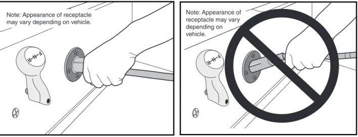
• Do not rock or bend the plug. To connect the charger plug to the vehicle receptacle, grasp the plug handle and push the plug straight into the receptacle (Figure 2).
• Do not pull on the DC cord (Figure 3). Do not twist, rock or bend the plug. To disconnect the charger plug from the vehicle receptacle, grasp the plug by the handle and pull the plug straight out of the receptacle.
• Do not connect a charger to the receptacle if the charger cord, plug, or the vehicle receptacle is broken, damaged in any manner, or does not make a good electrical connection. Fire or personal injury can result. Have it replaced by a qualified service person immediately. Failure to follow these instructions could result in damage to the charger cord, the plug, and (or) the vehicle receptacle.
Charger Installation and Operation
ý
WARNING
• Do not use a charger if:
- The plug is too loose or does not make a good connection. - The plug and receptacle feel hotter than normal during charge. - The plug pin or receptacle contacts are bent or corroded.
- The plug, receptacle, or cords are cut, worn, have any exposed wires or are damaged in any way.
• Using the charger with any of the above symptoms could result in a fire, property damage, personal injury, or death.
1. With the charger DC cord disconnected from the vehicle charger receptacle, connect the AC power sup-ply cord to an AC outlet designed to provide the proper AC voltage for the charger.
2. Connect the charger DC plug to the vehicle charger receptacle located on the seat support panel
(Figure 2). The charger will activate automatically within 2 to 15 seconds after the DC plug is connected.
See following WARNING.
ý
WARNING
• Do not rock or bend the plug. To connect the charger plug to the vehicle receptacle, grasp the plug handle and push the plug straight into the receptacle (Figure 2).
3. PowerDrive and PowerDrive Plus Vehicles:10 to 20 seconds after the charger activates, it will shut
off again to run a self-diagnostic program (the ammeter will drop to 0). Charging will resume in a few moments (ammeter will return to previous rate of charge).
4. Monitor the ammeter for the correct charge rate. The initial charge rate will vary from 12 to 16 amps, depending upon the condition and depth of discharge of the batteries. Variations in the initial charge rate may also result from AC line input voltages which are higher or lower than the nominal input voltage. Higher AC line voltages increase the initial charge rate while lower AC line voltages reduce the initial charge rate.
5. PowerDrive and PowerDrive Plus Vehicles:Monitor the ammeter for about 30 seconds. Under normal
operating conditions (when the charger is on and the batteries are discharged), the ammeter will drop to zero for 2 to 3 seconds at the beginning of each charge cycle in order to perform a self-diagnostic test. This test will be repeated at one hour and two hours into the charge cycle.
6. Excel and IQ System vehicles: At one hour and at two hours into the charge cycle, the charger will shut
off in order to run a self-diagnostic program (ammeter will drop to zero). Charging will resume in a few moments (ammeter returns to previous rate of charge). See following NOTE.
NOTE: PowerDrive and PowerDrive Plus Vehicles: If the batteries are in a fully charged state and the vehi-cle has not been driven, the onboard computer will not perform the self-diagnostic test.
Batteries should be put on charge at the end of each day even if the vehicle has been used for only a short amount of time (even if for only 10 minutes).
When air temperatures fall below 65 °F (18.3 °C), batteries charged in unheated areas should be placed on charge as soon as possible after use. Cold batteries require more time to fully charge, and batteries are warmest immediately after use.
New batteries will not deliver their full range until the vehicle has been driven and recharged from 20 to 50 times.
Charger Installation and Operation Vehicles should be restricted to 40 to 50 energy units of discharge (or 36 holes of golf) between charges until the batteries have been properly seasoned (20 to 50 charge cycles). For maximum battery life, Club Car recommends that electric vehicles always be recharged after 40 to 50 energy units of discharge or each night in order to avoid deep discharging the batteries. Charging between rounds will also extend battery life; use the CDM (Communication Display Module) (CCI P/N
101831801). See Communication Display Module in the appropriate maintenance and
ser-vice supplement.
If charger does not appear to be operating properly, or if the batteries appear to be weak, contact your Club Car distributor/dealer.
CHARGER PLUG AND RECEPTACLE
When inserting the DC plug into the vehicle receptacle, align the raised guide on the plug with the guide slot in the receptacle and slowly push plug straight in (Figure 2). To disconnect the plug from the vehicle, firmly grasp the plug, not the cord (Figure 3), and slowly pull plug straight out. See following WARNING.
ý
WARNING
• Do not rock or bend the plug. To connect the charger plug to the vehicle receptacle, grasp the plug handle and push the plug straight into the receptacle (Figure 2).
• Do not pull on the DC cord (Figure 3). Do not twist, rock or bend the plug. To disconnect the charger plug from the vehicle receptacle, grasp the plug by the handle and pull the plug straight out of the receptacle.
• The DC charger cord and plug are wear items and must be replaced when worn or damaged.
The charger cord, plug, and receptacle are wear items and should be inspected daily. Visually inspect them for cracks, loose connections, and frayed wiring; they must be replaced when worn or damaged. If charger plug or receptacle show signs of corrosion or the plug is difficult to insert or remove, the receptacle contacts and plug terminals should be cleaned with a good electrical contact cleaner. The plug should then be inserted and removed several times to ensure ease of insertion, ease of removal, and good electrical contact. See fol-lowing NOTE.
NOTE: If the warning tag has been damaged or removed from the DC cord, have it replaced immediately.
Figure 2 Charger Receptacle Figure 3 Incorrect DC Plug Removal
Note: Appearance of receptacle may vary depending on vehicle.
Note: Appearance of receptacle may vary depending on vehicle.
Checking Battery Condition After a Charge Cycle
CHECKING BATTERY CONDITION AFTER A CHARGE CYCLE
Read DANGER, WARNING, and CAUTIONS beginning on page 7.
It is common practice for technicians to check the condition of a set of batteries after they have been charged to ensure they have received a complete charge before the vehicle is used. With IQ System, PowerDrive, PowerDrive Plus and Excel System vehicles, this is not necessary; the onboard computer controls and mon-itors the charge cycle. If any problem occurs during a charge cycle, the battery warning light, located above the steering column in the center dash panel, will illuminate intermittently.
If the battery warning light is illuminated after a charge cycle, refer to the troubleshooting chart in the mainte-nance and service manual appropriate for your battery charger. If you do not have this publication, contact your Club Car representative. If the specified test procedures identify no problems, plug the DC cord into the vehicle and let it charge until the charger shuts off automatically. If a problem is found, correct it and then charge the vehicle. Normal voltage near the end of a charge cycle should be approximately 59 to 63 volts.
START CHARGE CYCLE
1. Disconnect the DC plug from the vehicle charger receptacle.
2. Wait 20 seconds, then reconnect the DC cord to the vehicle receptacle. See following NOTE.
NOTE: The charger will not operate unless a delay of approximately 20 seconds is observed.
3. Monitor the ammeter for the charge rate. If the vehicle has not been driven since the last charge cycle and the batteries are fully charged, the onboard computer will not perform a self-diagnostic test. The charge cycle will begin and the ammeter will not drop to zero. If the vehicle has been driven, even if only a few feet, the onboard computer will perform the self-diagnostic test; the ammeter will drop to zero for 2 to 3 seconds before the charge cycle continues. If the batteries are close to being fully charged, the charge cycle will begin and the charge current will begin to taper within a few minutes.
Battery Charger Specifications
BATTERY CHARGER SPECIFICATIONS
POWERDRIVE 3 (MODEL 26560)
BATTERY CHARGER
SPECIFICATIONS
PowerDrive 3 Battery Charger (Model 26560)
MODEL Model number (Part number (CCI))
26560-11 (103394401)
26560-18 (103394402)
26560-19 (103394403) AC INPUT
AC voltage: 105-128 VAC • • •
Frequency: 60 Hz. • • •
POWER CONSUMPTION
AC current (amps) 9.5 9.5 9.5
AC wattage (watts) 1140 1140 1140
DC OUTPUT
DC voltage (start of charge cycle) 48 48 48
DC current (start of charge cycle) 14.5 14.5 14.5
DC voltage (end of charge cycle) 60 60 60
DC current (amps) (end of charge cycle) 4.5 4.5 4.5
DIMENSIONS/WEIGHT
Case – overall depth (19.8 cm)7.8 in. (19.8 cm)7.8 in. (19.8 cm)7.8 in.
Case – overall width (18.1 cm)7.13 in. (18.1 cm)7.13 in. (18.1 cm)7.13 in.
Case – overall height (24.8 cm)9.75 in. (24.8 cm)9.75 in. (24.8 cm)9.75 in.
AC cord length (182.9 cm)72 in. (264 cm)104 in. (264 cm)104 in.
DC cord length (264 cm)104 in. (365.8 cm)144 in. (609.6 cm)240 in.
Weight 24.25 lb.(11 kg) (11.2 kg)24.7 lb. 25.35 lb.(11.5 kg)
MOUNTING CONFIGURATION
Mounting: Set on shelf, wall mount with keyhole, or hang securely
Battery Charger Specifications
POWERDRIVE 3
(MODEL 26580)
BATTERY CHARGER
SPECIFICATIONS
PowerDrive 3 Battery Charger (Model 26580)
MODEL Model number (Part number (CCI))
26580-11 (103499101)
26580-18 (103499102)
26580-19 (103499103)
26580-31 (103717001)
26580-38 (103717002)
26580-39 (103717003) AC INPUT
AC voltage:105-128 VAC • • • • • •
Frequency:60 Hz. • • • • • •
POWER CONSUMPTION
AC current (amps) 9.5 9.5 9.5 9.5 9.5 9.5
AC wattage (watts) 1140 1140 1140 1140 1140 1140
DC OUTPUT
DC voltage (start of charge cycle) 48 48 48 48 48 48
DC current (start of charge cycle) 14.5 14.5 14.5 14.5 14.5 14.5
DC voltage (end of charge cycle) 60 60 60 60 60 60
DC current (amps) (end of charge cycle) 4.5 4.5 4.5 4.5 4.5 4.5
DIMENSIONS/WEIGHT
Case – overall depth (19.8 cm)7.8 in. (19.8 cm)7.8 in. (19.8 cm)7.8 in. (19.8 cm)7.8 in. (19.8 cm)7.8 in. (19.8 cm)7.8 in.
Case – overall width (18.1 cm)7.13 in. (18.1 cm)7.13 in. (18.1 cm)7.13 in. (18.1 cm)7.13 in. (18.1 cm)7.13 in. (18.1 cm)7.13 in.
Case – overall height (24.8 cm)9.75 in. (24.8 cm)9.75 in. (24.8 cm)9.75 in. (24.8 cm)9.75 in. (24.8 cm)9.75 in. (24.8 cm)9.75 in.
AC cord length (182.9 cm)72 in. (264 cm)104 in. (264 cm)104 in. (182.9 cm)72 in. (264 cm)104 in. (264 cm)104 in.
DC cord length (264 cm)104 in. (365.8 cm)144 in. (609.6 cm)240 in. (264 cm)104 in. (365.8 cm)144 in. (609.6 cm)240 in.
Weight (10.89 kg)24.0 lb. (11.11 kg)24.5 lb. (11.8 kg)26.0 lb. (9.98 kg)22.0 lb. (10.2 kg)22.8 lb. (10.89 kg)24.1 lb.
MOUNTING CONFIGURATION
Mounting: Set on shelf, wall mount with
CLUB CAR
®
LIMITED FOUR YEAR WARRANTY FOR
POWERDRIVE
®
CHARGERS
CLUB CAR, INC., (“CLUB CAR”) hereby warrants to the original retail purchaser that its new PowerDrive Chargers purchased from CLUB CAR or an authorized distributor or dealer will be free from defects in material and workmanship under normal use and service for a period of four years from the date of purchase, subject to the terms, provisions, limitations, and exclusions contained herein.
The limited warranty with respect to parts and labor only covers defects in material and workmanship for a period of four years from the date of purchase. Such repair labor shall be performed only by CLUB CAR or by an authorized distributor or dealer. Purchaser shall be responsible for all freight costs to and from CLUB CAR’s facility.
LIMITED WARRANTY EXCLUSIONS
THE PROVISIONS OF THIS LIMITED WARRANTY SHALL NOT APPLY TO FAILURE DUE TO:
1) Lack of normal maintenance services such as preventive maintenance checks and tightening loose wire connections; 2) Semiconductor parts such as diodes and fuses which are vulnerable to electrical overloads (including lightning) beyond the control of CLUB CAR;
3) Charger DC cord set with plug, which is a wear item and subject to user abuse.
Any warranty service, which includes labor during the first year, must be performed by CLUB CAR or by an authorized distributor or dealer. For repairs made by qualified technicians other than CLUB CAR’s factory technicians or an authorized distributor or dealer, CLUB CAR will provide only the replacement parts or components.
The PowerDrive Chargers are intended to be used by persons with knowledge of the chargers and proper charging
practices and only on CLUB CAR PowerDrive System 48™, PowerDrive Plus®, IQ System™ and Excel™ System vehicles.
Any other use renders the Limited Warranties expressed herein and any implied warranties null and void and same are hereby excluded.
Without limiting the generality of the foregoing in any way, and as part of its limited warranty exclusion, CLUB CAR does not warrant that the PowerDrive Charger is suitable for use in any application other than its PowerDrive System 48, PowerDrive Plus, IQ System and Excel System products. As in the use of any electrical device, a prudent owner will read and study the charger owner’s manual, the electric vehicle owner’s manual, the operator instructions, and the battery warning labels; and will exercise due care in working on or around electrical devices.
Transportation expenses for warranty services are also excluded from this warranty.
WARRANTY LIMITATIONS
CLUB CAR’s liability under this limited warranty, or in any action whether based upon warranty, contract, negligence, strict product liability or otherwise, shall be the replacement or repair of a charger or component thereof that CLUB CAR deems to be defective. Replacement shall mean furnishing, during the applicable limited warranty period, a new charger or component thereof that is identical or reasonably equivalent to the warranted product or defective component at no cost to the purchaser. Repair shall mean remedying a defect in the charger or component thereof at no cost to the purchaser during the applicable limited warranty period. If CLUB CAR elects to repair the charger, it may provide factory-reconditioned parts or components. All parts and components replaced under warranty shall become the property of CLUB CAR.
THIS LIMITED WARRANTY IS EXCLUSIVE. CLUB CAR MAKES NO OTHER WARRANTY OF ANY KIND, EXPRESSED OR IMPLIED. ANY IMPLIED WARRANTIES OF MERCHANTABILITY OR FITNESS FOR A PARTICULAR PURPOSE WHICH EXCEED THE OBLIGATIONS OR TIME LIMITS STATED IN THIS WARRANTY ARE HEREBY DISCLAIMED BY CLUB CAR AND EXCLUDED FROM THIS WARRANTY. THE PURCHASER AND CLUB CAR EXPRESSLY AGREE THAT THE REPLACEMENT OR REPAIR OF THE DEFECTIVE VEHICLE OR COMPONENT THEREOF IS THE SOLE REMEDY OF THE PURCHASER. CLUB CAR MAKES NO OTHER REPRESENTATION OR WARRANTY OF ANY KIND AND NO REPRESENTATIVE, EMPLOYEE, DISTRIBUTOR OR DEALER OF CLUB CAR HAS THE AUTHORITY TO MAKE OR IMPLY ANY REPRESENTATION, PROMISE OR AGREEMENT, WHICH IN ANY WAY VARIES THE TERMS OF THIS WARRANTY.
IN NO EVENT SHALL CLUB CAR BE LIABLE FOR ANY INCIDENTAL OR CONSEQUENTIAL DAMAGES INCLUDING, BUT NOT LIMITED TO, LOSS RELATED TO PROPERTY OTHER THAN THE BATTERY CHARGER, LOSS OF USE, LOSS OF TIME, INCONVENIENCE, OR ANY OTHER ECONOMIC LOSS.
Damage not resulting from a defect that occurs due to unreasonable use, abuse or neglect (including failure to provide reasonable or necessary maintenance), accident or alteration is excluded from the limited warranty.
Some states allow neither limitation on the duration of an implied warranty nor exclusions or limitations of incidental or consequential damages. Therefore, the above limitations or exclusions may not apply to you.
This warranty gives you specific legal rights, and you may also have other rights, which vary from state to state.
For further information contact WARRANTY SERVICES, CLUB CAR, INC., P.O. Box 204658, Augusta, Georgia 30917-4658, U.S.A., 706-863-3000.
Club Car, LLC
P.O. Box 204658 Augusta, GA 30917-4658 USA
Web www.clubcar.com
Phone 1.706.863.3000
1.800.ClubCar
Intl’l +1 706.863.3000
Fax 1.706.863-5808