for Mobile Stations in FiWi Access Networks
© 2015 IEEE. Personal use of this material is permitted. Permission from
IEEE must be obtained for all other uses, in any current or future media,
including reprinting/republishing this material for advertising or
promotional purposes, creating new collective works, for resale or
redistribution to servers or lists, or reuse of any copyrighted component of
this work in other works.
This material is presented to ensure timely dissemination of scholarly and
technical work. Copyright and all rights therein are retained by authors or
by other copyright holders. All persons copying this information are
expected to adhere to the terms and constraints invoked by each author's
copyright. In most cases, these works may not be reposted without the
explicit permission of the copyright holder.
Citation:
Kei Saito, Hiroki Nishiyama, Nei Kato, Hirotaka Ujikawa, and Ken-Ichi Suzuki,
"A MPCP-Based Centralized Rate Control Method for Mobile Stations in FiWi
Access Networks," IEEE Wireless Communications Letters, vol. 4, no. 2, pp.
205-208, Apr. 2015.
URL:
Kei Saito,
Student Member, IEEE,
Hiroki Nishiyama,
Senior Member, IEEE,
Nei Kato,
Fellow, IEEE,
Hirotaka Ujikawa,
Member, IEEE, and
Ken-Ichi Suzuki,
Member, IEEE
Abstract—Fiber Wireless (FiWi) access networks is widely prevailed to connect the users to the core network. The FiWi access networks are consisted of the edge router, the Passive Optical Networks (PONs) and the wireless networks. In this environment, the edge router, which is the terminal to the core network, has the possibility of heavy congestion. To cope with this problem, we propose a Multi Point Control Protocol (MPCP)-based centralized rate control method to centrally control the traffic rate at each Home GateWay (HGW) so as to avoid congestion at the edge router. In the proposed scheme the transmission delay due to rate control overhead can be mitigated. The performance of the proposed scheme is verified by numerical analysis and computer simulations.
Index Terms—FiWi, PON, WLAN, HGW, MPCP.
I. INTRODUCTION
R
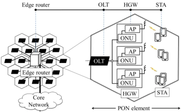
ECENTLY, the Passive Optical Networks (PONs) [1] and the Wireless Local Area Networks (WLANs) [2] have been widely used in the access networks, which connect users to the core network. The WLANs are used for the user networks and the PONs are used to connect the WLANs to the edge router, which is the final destination to the core network. Due to the increase of needs arising from the much anticipated 5th Generation (5G) cellular network whereby the allowable end-to-end delay is expected to be below 5ms, the needs of the lower delay in access networks is substantially increasing. The collaboration network of the PONs and the WLANs is called the Fiber Wireless (FiWi) access network [3], and this is attracting significant attention. Fig. 1 shows the network topology of FiWi access networks considered in this paper. The STAtion (STA) sends the data to a Home GateWay (HGW) with the distributed control. We assume that the HGW plays the role of both the Access Point (AP) and the Optical Network Unit (ONU), and is connected to an Optical Line Terminal (OLT). The ONUs are centrally controlled by the OLT with Multi Point Control Protocol (MPCP) [4]. Several OLTs are connected to an edge router. Due to the geographical location of the OLT, the propagation delay between the HGW and the edge router is different. The edge router does not impose control on the traffic at each OLT, however, it controls the data rate of the uplink traffic to the core network. In this network, since the HGW and the edge router do not centrally control the uplink traffic coming from the STA and the OLT, respectively,K. Saito, H. Nishiyama, and N. Kato are with the Graduate School of Information Sciences, Tohoku University, Sendai, JAPAN. E-mail: {keys, bigtree, kato}@it.ecei.tohoku.ac.jp.
H. Ujikawa and K. Suzuki are with the NTT Access Network Ser-vice Systems Laboratories, NTT Corporation, Yokosuka, Japan E-mail:
{ujikawa.hirotaka, suzuki.kenichi}@lab.ntt.co.jp
Fig. 1. An example of our considered FiWi access networks.
there is a possibility of uplink traffic congestion at both the HGW and the edge router.
As a method to solve the afore-mentioned traffic congestion problem, in this paper, we propose a method to apply the MPCP between the HGW and the edge router. In our proposed method, the edge router centrally controls the traffic rate from each HGW so that we can avoid the traffic congestion on the uplink in the FiWi access networks. As a traffic rate control method using MPCP, two different bandwidth sharing methods can be considered, i.e., time division and rate division schemes. The bandwidth sharing by time division leads to additional delays due to time scheduling, which is not negligible for real-time communications. Therefore, in terms of short delivery delay, the bandwidth sharing method in rate division is appropriate to avoid the traffic congestion. By this method, it may be possible to avoid the traffic congestion in the FiWi access networks with low delay.
The remainder of this paper is organized as follows. First, we introduce the centralized control method by using the MPCP with bandwidth sharing by time division and rate division in Section II. Then, we formulate the delay at the HGW to analyze the performance of the proposed method in Section III. In Section IV, we present the results of performance evaluation conducted by computer simulations. Finally, Section V concludes the paper.
II. ASSUMEDNETWORKENVIRONMENT
A. MPCP mechanism
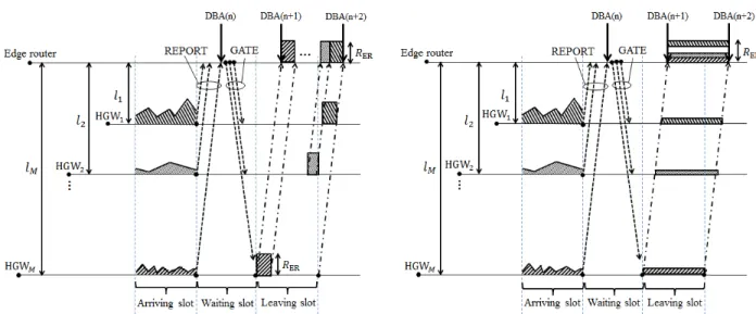
Figs. 2(a) and 2(b) demonstrate the mechanism of the MPCP with bandwidth sharing by time division and rate division,
(a) The MPCP with bandwidth sharing by time division. (b) The MPCP with bandwidth sharing by rate division. Fig. 2. The mechanism of MPCP with bandwidth sharing by time division and rate division.
respectively. In this centralized control method, the process to send the data can be divided into three time slots, namely arriving slot, waiting slot, and leaving slot. The lengths of those time slots are all the same and referred to as the Dynamic Bandwidth Allocation (DBA) intervals. In this centralized control method, the edge router controls the traffic rate from each HGW by exchanging control messages among them. Each HGW sends a REPORT message to the edge router, which informs the amount of data that arrives at the HGW during the last DBA interval. In the next waiting slot, the data which arrives in the arriving slot waits at the HGW while the edge router receives all REPORTs from each HGW. Then, the edge router sends a GATE message to each HGW informing the traffic rate. The policy of the method to allocate the bandwidth to each HGW, which is referred to as the DBA policy [4], [5], has been studied by many other researchers, and it is out of scope in this paper. Here, the DBA interval must be equal to or bigger than the maximum round trip time between the HGW and the edge router. Since we assume that the FiWi access networks in this paper are used as the access networks of the 5G, the length of the DBA interval is considered to be within 5ms.
B. Drawback of Bandwidth Sharing by Time Division
Fig. 2(a) depicts the sequence of the centralized control of applying the bandwidth sharing by time division. In this method, to divide the time at the edge router, the timing of sending data at each HGW in the leaving slot is different considering the gap of the propagation delay between the HGW and the edge router. In this time, each HGW can send the data with the link rate of the edge router. Therefore, the arriving traffic rate at the edge router is the same as the link rate of the edge router.
The bandwidth sharing by time division is used at the PON where the DBA interval is in the order of micro-seconds. On the other hand, the propagation delay between the HGW and the edge router is in the order of milli-seconds. Therefore, even
if the delay occurred by the time division between the OLT and the ONU is small enough to ignore, the delay cannot be ignored when the time division is applied between the HGW and the edge router. In case of Fig. 2(a), the data which arrives at the 1st HGW waits for the longest time due to waiting
for the DBA interval, and finally is sent to the edge router after all data is sent from the 2nd HGW to the Mth HGW
in the leaving time-slot. Here, for example, we assume that the distance between theMthHGW and the edge router,lM,
is the longest. From the above discussion, the MPCP with sharing bandwidth by time division is not appropriate between the edge router and the HGW.
C. Bandwidth Sharing by Rate Division
Fig. 2(b) shows the sequence of the centralized control of applying the bandwidth sharing by rate division. In this method, the time length to send the data is the same with each HGW, and it is equal to the DBA interval. We can control the traffic rate of each HGW and the start timing of the data from each HGW by sending the GATE message to each HGW. When each HGW sends data to the edge router in the leaving slot, the Mth HGW first begins to send the data with the
controlled traffic rate. Then, we make the arriving time of data from the 1st HGW to the(M
−1)th HGW at the edge
router the same with each other so that the edge router is able to keep the total traffic rate during the DBA interval. In order to realize this method, the data from the ith HGW starts to
be sent to the edge router in the gap of the propagation delay between theMthHGW and theithHGW after the data from
theMthHGW starts to be sent. By this method, we can avoid
the additional delay occurred in the bandwidth sharing method by time division.
III. ANALYSIS OF DELAY DUE TOMPCP-BASEDRATE
CONTROL
In this section, we formulate the delay at the HGW in the case of the bandwidth sharing by rate division. Then, we
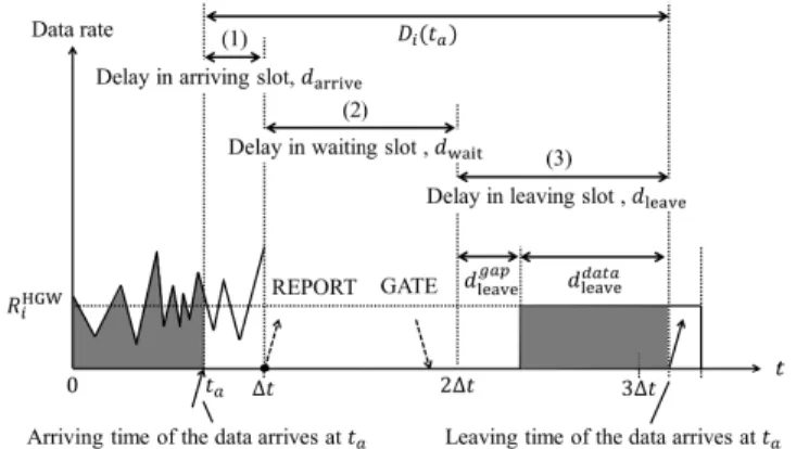
Fig. 3. The analytical model of the delay at the HGW.
analyze the delay to evaluate the performance of the proposed scheme.
A. Formulation of Delay at the HGW
We define the delay at the HGW as the time between the traffic arrives at the HGW and the traffic leaves from the HGW. The formulation is held on a premise that all data, which arrives at the ith HGW during the arriving slot, can
be sent to the edge router within the leaving slot. We set that the arriving traffic rate at the ithHGW from the STAs at the
time ta follows a function, fi(ta) with 0 ≤ ta ≤ ∆t. We
also assume that the propagation delay between an AP and an ONU in the same HGW is 0. The DBA interval is decided by the longest distance between the HGW and the edge router. Therefore, when we set the distance between thejthHGW and
the edge router aslj, the DBA interval meets an inequality as follows:
2×max j
lj
c ≤∆t, (1)
wherecdenotes the speed of light. Fig. 3 shows the analytical
model of the delay at the ith HGW, Di(ta). Di(ta) can be
divided into three different types of delays, i.e, the delay in the arriving slot, darrive, the delay in the waiting slot, dwait
and the delay in the leaving slot, dleaving.
In the arriving slot, the data that arrives at theith HGW at ta waits until the time when the REPORT is sent to the edge router. When we set the DBA interval as∆t, the delay in the arriving slot, darrive, can be calculated as (∆t−ta).
In the waiting slot, all data has to wait during a DBA interval where the HGW and the edge router exchange the REPORT and the GATE messages with each other. Thus,dwait is equal
to∆t.
The delay in the leaving slot is the sum ofdgapleaveandddata leave.
From Fig. 2(b), the ith HGW starts to send the data to the
edge router in dgapleave after the jth HGWs (i < j) send the
data. In this time,dgapleavecan be calculated from the gap in the propagation delays between the edge router and each HGW, and its maximum value can be expressed as follows:
dgapleave= max j
lj c −
li
c. (2)
0 0.5 1 1.5 2
0 0.2 0.4 0.6 0.8 1
T
he
de
la
y a
t t
he
H
The arrival time of the data to the HGW [ms]
Fig. 4. The delay experienced by different arrival times at the HGW.
Meanwhile, the sum of the data arriving at the ith HGW
between0totais equal to the sum of the data leaving from the HGW duringddata
leave. Therefore, when the edge router decides
the traffic rate of the ithHGW asRHGW
i ,ddataleavebecomes as
follows:
ddataleave=
!ta
0 fi(τ)dτ RHGW
i
. (3)
Hence, the delay in the leaving slot can be calculated by the sum of Eqs. 2 and 3.
From the above formula, we can derive Di(ta)as the sum
of them as follows:
Di(ta) = darrive+dwait+dleave = (∆t−ta) +∆t
+ max j
lj c −
li c +
!ta
0 fi(τ)dτ RHGW
i
. (4)
From Eq. 4, both the delays in the arriving slot and the waiting slot are the same with all the HGWs. However, the delay in the leaving slot depends on the value ofi.
B. Numerical analysis
In this section, we analyze the delay formulated as Eq. 4. Assuming that the propagation delay between the ith HGW
and the edge router is much smaller than the DBA interval, i.e.,li/c≪∆t, Eq. 4 can be transformed into the equation as
follows:
Di(ta) = (∆t−ta) +∆t+
!ta
0 fi(τ)dτ RHGW
i
. (5)
Here, we consider the proportional fairness as a DBA policy where the edge router decides the traffic rate by the proportion of the amount of data which the ith HGW demands against
the whole demands.RHGW
i can be given as follows: RHGWi =RER×
!∆t 0 fi(τ)dτ
"M j
!∆t
0 fj(τ)dτ
, (6)
where RER denotes the link rate of the edge router. Here,
we assume the premise that all the traffic which arrives at the HGWs are equal to the upper bound of the transmittable
traffic amount during a DBA interval. Then following equation is satisfied:
M
#
j
$ ∆t 0
fj(τ)dτ=RER
×∆t. (7) Therefore, from Eqs. 6 and 7, the delay can be expressed simply as follows:
Di(ta) =
%
2 +
!ta
0 fi(τ)dτ
!∆t 0 fi(τ)dτ
&
∆t−ta. (8)
From Eq. 8, we can understand that the delay at the ith
HGW only depends on its own traffic arrival function, fi(ta),
regardless of the other HGWs’ traffic patterns.
To visualize the shape of Di(ta), here, we assume that fi(ta)follows the normal distribution function as follows:
fi(ta) =
⎧ ⎪ ⎨ ⎪ ⎩ (2πσ2
i)−1/2exp
+
−(ta−µi)2
2σ2i ,
×(RER
·∆t), (µi−3σi≤ta≤µi+ 3σi) 0, (otherwise)
(9) where µi and σi denote the time of the peak traffic rate and
the variance of the distribution, respectively. For the feature of the normal distribution function, the integral offi(ta)from (µi −3σi) to (µi + 3σi) is more than 99% of (RER·∆t).
In other words, the amount of the arriving traffic becomes almost equal to the upper bound of the leaving traffic when both (0≤µi−3σi) and (µi+ 3σi ≤∆t) are satisfied. In such
a situation, we set µi,σi, and∆tto∆t/2,∆t/10, and 1ms,
respectively, and depict the delayDi(ta)in Fig. 4. The delay in
the leaving slot,dleave, suddenly increases aroundµi and gets
gently stable during the beginning and the end. This is because the amount of arriving data at the HGW suddenly increases around the µi and gets stabilized at the beginning and the end. Therefore, the total delay, Di(ta), shows the minimum delay at the time before the peak of the arriving data, and the maximum value at the time after the peak of the arriving data.
IV. PERFORMANCE EVALUATION
In this section, we evaluate the minimum and maximum delays observed at the HGWs through extensive computer-based simulations with comparisons between the theoretical and analytical values.
We assume that the 19 OLTs are located around the edge router as shown in Fig. 1. Each OLT is connected by 8 HGWs so that the total number of HGWs,M, is 152. We set theRER
to 1Gbps. We vary the∆tfrom 0.1ms to 1.0ms by intervals of 0.1ms. In the conducted simulations, we generate the uplink traffic to each HGW from its STAs according to Eq. 9 by randomly varying the value of σi between 0.001 and ∆t/6,
and the value of µi between3σi and (∆t−3σi).
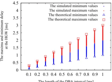
Fig. 5 shows the relationship between the length of the DBA interval, and the maximum and minimum values of the delay observed at the HGW. The theoretical maximum value can be derived from Eq. 4 with ta = 0, which corresponds to the
case where all traffic volumes equal to (RER·∆t) arrive at ta= 0. On the other hand, the theoretical minimum value can
be derived from Eq. 4 with ta =∆t, which corresponds to
0 0.5 1 1.5 2 2.5 3 3.5 4 T he m axi m u a nd m ini m um de la y at t he H G W [ m s]
The length of the DBA interval [ms] The simulated minimum values The simulated maximum values The theoretical minimum values The theoretical maximum values
0.2 0.4 0.6 0.8 1
0.1 0.3 0.5 0.7 0.9
Fig. 5. The result of the maximum and minimum delays at the HGW against the length of the DBA interval.
the case where all traffic volumes equal to (RER·∆t) arrive
atta=∆t. It is confirmed that the simulated value is plotted
between the theoretical maximum and minimum values, which validates the analytical model. From the results, we can make
Di(ta) from 1 to 3 times of the length of the DBA interval by the proposed method. We can make the minimum value within only 1ms and the maximum value is also only within 3ms, which is lower than 5ms (i.e., the stated needs of the 5G). Therefore, we can confirm that our proposed method can enable the access FiWi networks to avoid the data losses while satisfying the allowable delay.
V. CONCLUSION
In this paper, we focused on the FiWi access networks in which the edge router adopts a centralized control against each HGW to avoid congestions. Due to the needs of low delay to the FiWi access networks by, for example, 5G, we proposed the MPCP with bandwidth sharing by rate division to meet the allowable delay. Then, we analyzed the delay at the HGW to evaluate the performance of the proposed method. By the analytical and simulated results, we confirmed that the proposed method is able to avoid congestions with allowable delay.
REFERENCES
[1] M. Ruffini, D. Mehta, B. O”Sullivan, L. Quesada, L. Doyle, and D. Payne, “Deployment strategies for protected long-reach pon,”Optical Communi-cations and Networking, IEEE/OSA Journal of, vol. 4, no. 2, pp. 118–129, February.
[2] B. Kannhavong, H. Nakayama, Y. Nemoto, N. Kato, and A. Jamalipour, “A survey of routing attacks in mobile ad hoc networks,” Wireless Communications, IEEE, vol. 14, no. 5, pp. 85–91, October.
[3] Y. Li, J. Wang, C. Qiao, A. Gumaste, Y. Xu, and Y. Xu, “Integrated fiber-wireless (fiwi) access networks supporting inter-onu communications,”
Lightwave Technology, Journal of, vol. 28, no. 5, pp. 714–724, March1,. [4] M. McGarry, M. Reisslein, and M. Maier, “Ethernet passive optical network architectures and dynamic bandwidth allocation algorithms,”
Communications Surveys Tutorials, IEEE, vol. 10, no. 3, pp. 46–60, 2008. [5] K. Yang, S. Ou, K. Guild, and H.-H. Chen, “Convergence of ethernet pon and ieee 802.16 broadband access networks and its qos-aware dynamic bandwidth allocation scheme,”Selected Areas in Communications, IEEE Journal on, vol. 27, no. 2, pp. 101–116, 2009.