Coaxial Cable
Performance and
Application Guide
COAXIAL CABLE
PERFORMANCE AND APPLICATION GUIDE
Content Page
1. INTRODUCTION . . . 1
2. GENERIC SYSTEM OVERVIEW . . . 2
3. CABLE SPECIFICATIONS . . . 3
4. CABLE RECOMMENDATIONS . . . 4
5. DS3 CABLING SUMMARY . . . 6
6. SYSTEM INTEGRATION SERVICES . . . 11
7. CUSTOMER SUPPORT SERVICES . . . 11
RECOMMENDED PROCEDURES FOR COAXIAL TERMINATION TYPE 728 CABLE WITH BNC AND TNC STRAIGHT PLUG CONNECTORS WITH LOCKING CENTER CONDUCTOR . . . 13
RECOMMENDED PROCEDURES FOR COAXIAL TERMINATION TYPE 728 CABLE WITH BNC 90 DEGREE PLUG CONNECTORS . . . 15
RECOMMENDED PROCEDURES FOR COAXIAL TERMINATION TYPE 734A CABLE WITH BNC AND TNC STRAIGHT CONNECTORS WITH LOCKING CENTER CONDUCTOR . . . 17
RECOMMENDED PROCEDURES FOR COAXIAL TERMINATION TYPE 734A CABLE WITH BNC 90 DEGREE PLUG CONNECTORS . . . 19
RECOMMENDED PROCEDURES FOR COAXIAL TERMINATION TYPE RG59B/U CABLE WITH BNC AND TNC STRAIGHT CONNECTORS WITH LOCKING CENTER CONDUCTOR . . . 21
RECOMMENDED PROCEDURES FOR COAXIAL TERMINATION TYPE RG59B/U CABLE WITH BNC 90 DEGREE PLUG CONNECTORS . . . 23
RECOMMENDED PROCEDURES FOR COAXIAL TERMINATION TYPE 735A CABLE WITH BNC AND TNC STRAIGHT CONNECTORS WITH LOCKING CENTER CONDUCTOR . . . 25
RECOMMENDED PROCEDURES FOR COAXIAL TERMINATION TYPE 735A CABLE WITH BNC 90 DEGREE PLUG CONNECTORS . . . 27
RECOMMENDED PROCEDURES FOR COAXIAL TERMINATION TYPE 0222 CABLE WITH BNC AND TNC STRAIGHT CONNECTORS WITH LOCKING CENTER CONDUCTOR . . . 29
RECOMMENDED PROCEDURES FOR COAXIAL TERMINATION TYPE 0222 CABLE WITH BNC 90 DEGREE PLUG CONNECTORS . . . 31
1. INTRODUCTION
1.01
Dynamic expansion of DS3 transmission has challenged network planners and
engineers to seek new and practical ways to plan for this growth while maintaining network
performance at acceptable levels. DS3 network services have significantly impacted the
need for increased density in the DSX-3 arena.
1.02
This need for increased density is driven by the shortage of office space and a desire
to maximize new and existing line-ups while maintaining the DSX-3 pulse template,
voltage, and power requirements. As density has increased in DSX-3 products, cable used
to terminate these products has evolved from 728-type cable to smaller RG59/735-type
cables. Even with high density DSX-3 products and smaller coaxial cable; however, the
DSX-3 area continues to expand to larger line-ups in which the cross-connects are
exceed-ing the 27-foot limitation.
1.03
In order to address the issues of higher densities and equipment compatibilities,
interface standards such as Compatibility Bulletins, Technical Advisories and the American
National Standards have been established. The T1 Telecommunications Technical
Com-mittee, an accredited sub-committee of the American National Standards Institute (ANSI),
was established in 1984. ADC Telecommunications is an active member company of this
technical committee. Representatives making up this committee are manufacturers and
service and network providers who are working to establish interface standards for the
telecommunications industry.
2. GENERIC SYSTEM OVERVIEW
2.01
The DS3 transmission facility consists of several components that make up the
network. Of specific concern is the equipment typically located in the central office (CO)
where signals are handed off from carrier to carrier. Throughout this complex network, all
signaling eventually reaches a central location - the digital signal cross-connect (DSX)
point. The DSX forms a centralized cross-connect (digital distribution frame) for these
digital signals.
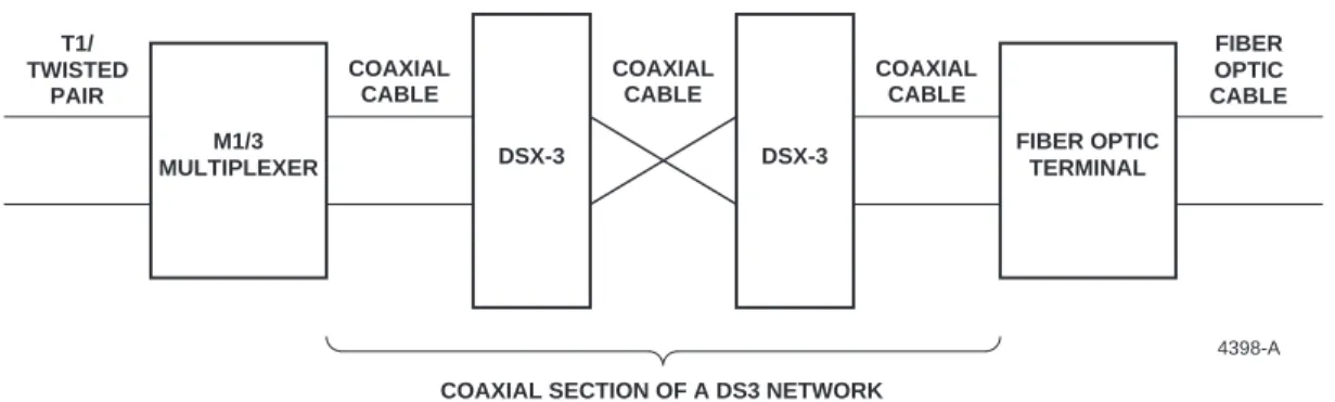
2.02
The DSX-3 system is designed for a specific signal level at the 45 Mb/s DS3 signal
rate. In a typical installation as shown in Figure 1, all digital equipment is terminated at the
DSX-3. In order to assure equal signal levels (equal voltage, power level, correct digital
pulse shape, and matching line impedance), output levels of all digital equipment are
equalized by customer-supplied components.
T1/ TWISTED PAIR M1/3 MULTIPLEXER COAXIAL CABLE COAXIAL CABLE COAXIAL CABLE FIBER OPTIC CABLE DSX-3 DSX-3 FIBER OPTIC TERMINAL
COAXIAL SECTION OF A DS3 NETWORK
4398-A
Figure 1. Typical DS1-to-DS3-to Fiber Network
2.03
Several types of customer-supplied signal treatments to establish equal levels and
pulse shape characteristics are used to compensate for the effects of the transmission
medium. These include attenuator pads, equalizers, line build-out (LBO) networks,
match-ing networks, and automatic line build-outs (ALBOs).
2.04
The level of the signal applied to the cable pair must be set in accordance with the
physical location of the signal source along the transmission medium. This is done to assure
that equal levels of the signal traverse the cable in the same direction as the signal sources.
The advantage of equal-level transmission is that signals arrive at their destinations at the
same nominal level, therefore simplifying digital equipment processing, reducing
cross-talk, and minimizing mutual interference between adjacent channels.
2.05
Line build-outs (LBOs) and attenuator pads are used at the transmitter or source
equipment to pre-distort or pre-shape the transmission waveform. This compensates for
variations in cable length and other operational environments between the signal source and
the DSX equal-level point.
2.06
Matching networks are used to compensate for echoes caused by impedance
mis-matches. These irregularities are an important source of waveform distortion. Improved
impedance matching at junctions in the transmission medium is a good method for reducing
this type of signal distortion/variation.
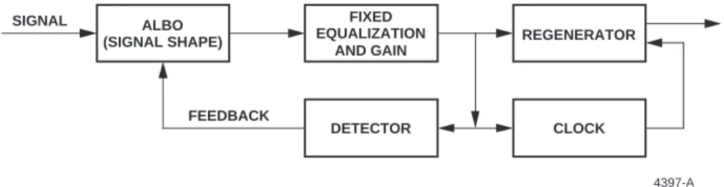
2.07
Equalizers and automatic line build-outs (ALBOs) are used at the receive equipment
to establish the proper signal level and pulse shape required by the receiver. This is referred
to as the input sensitivity of the receiving device. An ALBO circuit followed by an amplifier
incorporates fixed equalization and gain. Typically, the fixed section incorporates the
appropriate gain and equalization for the maximum expected cable loss. The output of the
fixed equalizer is sampled by a detector that provides feedback to the ALBO section, adding
frequency-shaped loss until the total fixed and shaped output signal reaches the desired
value (see Figure 2).
ALBO (SIGNAL SHAPE) FIXED EQUALIZATION AND GAIN REGENERATOR CLOCK DETECTOR FEEDBACK SIGNAL 4397-A
Figure 2. Typical Automatic Line Build-out (ALBO) Circuit
2.08
These build-out networks and equalization techniques, in addition to the cable
characteristics, constitute the transmission environment. Cross-talk, noise thresholds,
trans-mitter power and receiver sensitivity are also key considerations in determining
perfor-mance requirements during network planning for any given transmission medium.
3. CABLE SPECIFICATIONS
3.01
Based on Bellcore Specification TR-NPL-000320 and ANSI Standard
T1.102-1987, cable characteristics have been used to establish a transmission loss budget that
includes 11 dB of insertion loss for IN and OUT cables, and 1.15 dB of insertion loss for the
3.02
The maximum distance from the transmission/multiplex equipment to the DSX
termination is 450 feet (137.16 m), depending on cable type. The maximum DSX
connect cable length has been established at 27 feet from the OUT to the IN circuit
cross-connection. Cable length from the DSX to the terminal equipment is also 450 feet,
maximum.
4. CABLE RECOMMENDATIONS
4.01
The maximum length recommended for IN and OUT cross-connect cables is based
on a generic cable; however, specific cables exhibit their own unique characteristics.
Figure 3 discusses the key cable-selection considerations and provides the formula used for
calculating the cable lengths listed in Table 1. Table 1 lists the system cable length limits for
IN/OUT cables and cross-connect cables for the DS3 transmission environment, based on
the already-mentioned 11.00 dB and 1.15 dB cross-connect frame budgets. The information
provided may be used as a rule of thumb for system planning and limitation approximations
based on variables designed into the network as a result of the cable type and DSX
equipment selected for the individual application. When cross-connects exceed
recom-mended lengths, DS3 intra-office repeaters should be used to ensure proper network
performance.
4408-B dB=A∅ (Ld)(Ls) (Fd) (Fs) 0.484 dB=A∅ (Ld)(Ls) (Fd)(Fs) 0.484 dB=A∅ 2.574100 22.368 MHz 100 MHz 22.368 MHz 100 MHz where: dB = Insertion Loss A∅ = Specified Attenuation Ld = Desired Length of Cable Ls = Specified Length of Cable Fd = Desired Frequency Fs = Specified FrequencyExample:
Total Loss Budget DSX Loss Remainder for X-Conn
1.150 dB 0.666 dB 0.484 dB
For 728 cable, A∅ = 2.574 dB loss for 100 feet of cable at 100 MHz.
(Ld)
Ld = (100)(0.484 dB) 2.574
= 39.757 Equal level transmission for the purposes of
minimizing transmission disturbances has been deployed in the network. This has resulted in establishment of the power levels and sensitivity levels of the transmit and receive equipment, as well as established the appropriate levels at the DS3 cross-connect. In addition, attenuation loss budgets have been established for the interconnecting cable and DSX-3 cross-connect.
The DSX-3 cross-connect is assigned an insertion loss budget of 1.15 dB, maximum, at 22.368 MHz, including the loss of 27 feet of cross-connect cable (728 or equal). The In/Out cabling insertion loss is assigned 11.0 dB at 22.368 MHz. This is based on actual cable measurements of AT&T 728 cable at a length of 900 feet.
The basis for these specifications results from attenuation of a coaxial transmission line. Assuming the transmission line follows an approximate ÷f (root frequency) law, the transmission medium insertion loss can be estimated using the formula shown at right if the following characteristics are known: Nominal attenuation for a specified length of cable at a specified frequency.
4.02
With the loss characteristics identified, a logarithmic curve was established and was
used to create a formula that determined the cable loss at specific frequencies.
4.03
ADC cautions against shortening the IN/OUT cables in order to further extend the
cross-connect lengths. Shortening the IN/OUT cables or removing the LBOs changes the
signal level at the DSX and may overload the receiving equipment, resulting in transmission
errors. Also, the signal will no longer be at an equal level. If the signal is out of equal level,
it will have an impact on the flexibility of the patching and cross-connect rearrangement at
the DSX-3.
4.04
Table 1 lists the eight types of cables that are used as cross-connects. Each cable type
was tested to verify the insertion loss characteristic. The cross-connect lengths were
deter-mined by testing the loss of 100 feet of cable from 10 MHz to 500 MHz (735A cable was
tested at 10 MHz to 300 MHz). The loss characteristics differ in each type of cable;
consequently, the maximum length for each cable differs. The specific cross-connect lengths
were determined by adding together the loss of IN/OUT cable (from equipment to DSX-3 and
from DSX-3 to equipment) and the loss of the specific cross-connect cable. Total system loss
budget allowed for the matrix (end-to-end loss) was 11.00 dB for IN/OUT cables and 1.15 dB
for the two DSX-3 modules and cross-connect patch cords, for a 12.15 dB maximum.
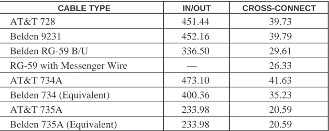
Table 1. Maximum Length in Feet @ 22.368 MHz (DS3)
CABLE TYPE IN/OUT CROSS-CONNECT
AT&T 728 451.44 39.73
Belden 9231 452.16 39.79
Belden RG-59 B/U 336.50 29.61
RG-59 with Messenger Wire — 26.33
AT&T 734A 473.10 41.63
Belden 734 (Equivalent) 400.36 35.23
AT&T 735A 233.98 20.59
Belden 735A (Equivalent) 233.98 20.59
The cable lengths shown in this matrix are actual loss characteristics of the
cable and are not affected by either the LBOs or the ALBOs.
5. DS3 CABLING SUMMARY
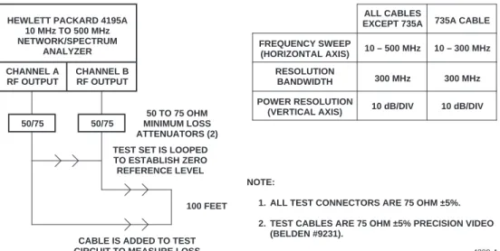
5.01
The insertion loss test diagram and graphs were used to determine the loss of the
DS3 cable found in the cabling matrix. Each cable was tested using a Hewlett Packard
4195A Network/Spectrum Analyzer and two 50-to-75 ohm minimum loss attenuators as
shown in Figure 4.
CHANNEL A RF OUTPUT
CHANNEL B RF OUTPUT HEWLETT PACKARD 4195A
10 MHz TO 500 MHz NETWORK/SPECTRUM ANALYZER 50/75 50/75 50 TO 75 OHM MINIMUM LOSS ATTENUATORS (2) TEST SET IS LOOPED TO ESTABLISH ZERO REFERENCE LEVEL
100 FEET
CABLE IS ADDED TO TEST CIRCUIT TO MEASURE LOSS
NOTE:
1. ALL TEST CONNECTORS ARE 75 OHM ±5%. 2. TEST CABLES ARE 75 OHM ±5% PRECISION VIDEO
(BELDEN #9231).
4399-A
FREQUENCY SWEEP (HORIZONTAL AXIS)
ALL CABLES
EXCEPT 735A 735A CABLE
10 – 500 MHz RESOLUTION
BANDWIDTH 300 MHz
POWER RESOLUTION
(VERTICAL AXIS) 10 dB/DIV
10 – 300 MHz
300 MHz
10 dB/DIV
Figure 4. Insertion Loss Test Diagram
5.02
Each cable was cut to a length of 100 feet and terminated with two 75 ohm BNC
connectors. Tests were conducted by using a frequency sweep of 10 MHz to 500 MHz
(10 MHz to 300 MHz for 735 cable), which established the loss characteristics over the
frequency spectrum. Examples of the loss characteristics are as follows:
Cable Type: AT&T 728A
N FREQUENCY (MHZ) T/R (DB) 1 5.000 –552.557 m 2 10.000 –790.917 m 3 22.368 –1.18029 4 44.736 –1.67493 5 100.000 –2.57599 6 137.088 –3.02297 7 274.176 –4.41578 8 300.000 –4.62584 9 400.000 –5.44602 10 500.000 –6.24945 MEASURE N = 1 START: 10.000 MHz SWEEP N = 1 10 STOP: 500.000 MHz RBW: 300 MHz ST: 961 msec RANGE: R = –10, T = –10 dBm
Cable Type: Belden 9231 N FREQUENCY (MHZ) T/R (DB) 1 5.000 –545.044 m 2 10.000 –780.265 m 3 22.368 –1.16242 4 44.736 –1.66100 5 100.000 –2.57188 6 137.088 –3.04064 7 274.176 –4.50114 8 300.000 –4.71158 9 400.000 –5.57823 10 500.000 –6.41853 MEASURE N = 1 START: 10.000 MHz SWEEP N = 1 10 STOP: 500.000 MHz RBW: 300 MHz ST: 961 msec RANGE: R = –10, T = –10 dBm
Cable Type: Belden RG59B/U
N FREQUENCY (MHZ) T/R (DB) 1 5.000 –719.759 m 2 10.000 –1.06672 3 22.368 –1.58501 4 44.736 –2.26379 5 100.000 –3.45587 6 137.088 –4.09302 7 274.176 –5.97215 8 300.000 –6.24465 9 400.000 –7.30770 10 500.000 –8.36582 MEASURE N = 1 START: 10.000 MHz SWEEP N = 1 10 STOP: 500.000 MHz RBW: 300 MHz ST: 961 msec RANGE: R = –10, T = –10 dBm
Cable Type: Belden 734A N FREQUENCY (MHZ) T/R (DB) 1 5.000 –720.557 m 2 10.000 –1.03163 3 22.368 –1.45540 4 44.736 –1.99143 5 100.000 –2.90465 6 137.088 –3.37880 7 274.176 –5.12830 8 300.000 –5.38508 9 400.000 –6.51667 10 500.000 –7.61800 MEASURE N = 1 START: 10.000 MHz SWEEP N = 1 10 STOP: 500.000 MHz RBW: 300 MHz ST: 961 msec RANGE: R = –10, T = –10 dBm
Cable Type: AT&T 734A
N FREQUENCY (MHZ) T/R (DB) 1 5.000 –540.877 m 2 10.000 –773.827 m 3 22.368 –1.13923 4 44.736 –1.61299 5 100.000 –2.45805 6 137.088 –2.87812 7 274.176 –4.18948 8 300.000 –4.37842 9 400.000 –5.09585 10 500.000 –6.81242 MEASURE N = 1 START: 10.000 MHz SWEEP N = 1 10 STOP: 500.000 MHz RBW: 300 MHz ST: 961 msec RANGE: R = –10, T = –10 dBm
Cable Type: RG59 with Messenger Wire N FREQUENCY (MHZ) T/R (DB) 1 5.000 –814.220 m 2 10.000 –1.14902 3 22.368 –1.76918 4 44.736 –2.52810 5 100.000 –3.88540 6 137.088 –4.60034 7 274.176 –6.73806 8 300.000 –7.10182 9 400.000 –8.29260 10 500.000 –9.50753 MEASURE N = 1 START: 10.000 MHz SWEEP N = 1 10 STOP: 500.000 MHz RBW: 300 MHz ST: 961 msec RANGE: R = –10, T = –10 dBm
Cable Type: 735A
N FREQUENCY (MHZ) T/R (DB) 1 8.448 –1.43 2 17.184 –2.03 3 22.368 –2.32 4 34.368 –2.89 5 44.736 –3.03 6 69.632 –4.13 7 77.760 –4.37 8 100.000 –4.97 9 139.264 –5.88 10 155.200 –6.25 MEASURE N = 1 START: 10.000 MHz SWEEP N = 1 10 STOP: 300.000 MHz RBW: 300 MHz ST: 961 msec RANGE: R = –10, T = –10 dBm
BNC Connector Specifications
PARAMETER SPECIFICATION
Electrical
Characteristic Impedance 75Ω± 5%
Voltage Rating 1000 Volts RMS
Insertion Loss < 0.6 dB, 1 MHz to 1 GHz (measured with
1 meter of 728 cable)
Return Loss ≤ –26 dB, 1 MHz to 1 GHz
Contact Resistance 0.030 Ω maximum change, post-environmental
Insulation Resistance 200 megohms, minimum
Mechanical
Mechanical Durability 500 cycles minimum
Center Contact Retention 4 lbs minimum
Coupling Mechanism Retention Force 100 lbs minimum
Cable Bend and Twist 500 cycles minimum (or failure of the cable,
whichever comes first)
Force to Engage/Disengage Torque 2.5 in/lb maximum
Longitudinal force 3.5 lbs maximum, 5.0 lbs maximum, post-environmental
Environmental
Thermal Shock –40° to 65° C operating, –55° to 85° C
non-operating
Moisture Resistance 0 to 95%, relative humidity, MIL-STD-202
Method 106
Corrosion (Salt Spray) MIL-STD-202 Method 101, Test Condition B
Flammability UL 94-VO rated (center conductor insulator)
Vibration MIL-STD-202 Method 201
Solvent Resistance MIL-STD-202 Method 215
Finish
Body/Bayonet Electroless nickel plate, tarnish resistant
Center Conductor 50 millionths inch gold plating,
6. SYSTEM INTEGRATION SERVICES
6.01 ADC offers the following system integration services. For calls originating in the U.S.A. or Canada, dial 1-800-366-3891, extension 3000. For calls originating outside the U.S.A. or Canada, dial
612-946-3000.
Technical Assistance Center • Product Management • Project Engineering • Project Administration • Network Design
• Broadband Design (RF Design and Strand Mapping) • Integration Network Testing
• Network Monitoring (Upstream or Downstream) • Power Monitoring
• Remote Surveillance • System Turn-Up and Test • Service/Maintenance Agreements
Technical Training • Product Technology • Custom Designed Training
Technical Operations • Detail Engineering • End-to-End Installation • Drafting Services
7. CUSTOMER SUPPORT SERVICES
7.01 ADC offers the following customer support services. For calls originating in the U.S.A. or Canada, dial 1-800-366-3891, then request the extension listed. For calls originating outside the U.S.A. or Canada, dial 612-946-3475 or 612-946-3000.
BCG Technical Assistance Center • Technical Information
Extension 3475 • System/Network Configuration
E-Mail: [email protected] • Product Specification • Product Application • Training
• Installation and Operation Assistance • Troubleshooting and Repair
• Field Assistance
Sales Administration • Quotation Proposals
Extension 3000 • Ordering • Delivery
• General Product Information
Product Return Department • ADC Return Authorization number and instructions
Extension 3000 must be obtained before returning products.
E-Mail: repair&[email protected]
7.02 Product information and service can also be obtained by writing ADC Telecommunications, Inc., 4900 West 78th Street, Minneapolis, Minnesota 55435, U.S.A.
Contents herein are current as of the date of publication. ADC reserves the right to change the contents without prior notice. In no event shall ADC be liable for any damages resulting from loss of data, loss of use, or loss of profits and ADC further disclaims any and all liability for indirect, incidental, special, consequential or other similar damages. This disclaimer of liability applies to all products, publications and services during and after the warranty period. This publication may be verified at any time by contacting ADC’s Technical Assistance Center at 1-800-366-3891, extension 3475 (in U.S.A. or Canada) or 612-946-3475 (outside U.S.A. and Canada), or by writing to ADC Telecommuni-cations, Inc., Attn: Technical Assistance Center, Mail Station #77, 4900 West 78th Street, Minneapolis, MN 55435, U.S.A.
© 1996, ADC Telecommunications, Inc. All Rights Reserved Printed in U.S.A.
4603-A
Recommended Procedures for Coaxial Termination
Type 728 Cable with BNC and TNC Straight
Connectors with Locking Center Conductor
This procedure provides the information to select cable, connectors, and the tools needed to
terminate coaxial connectors on the coaxial cable at the customer location.
COAXIAL
COAXIAL CABLE CONNECTOR
WECO Type 728 BNC-728D
TNC-728D
Belden 8281 BNC-8281D
Belden 9231 BNC-9231D
The step-by-step terminating instructions are shown on the reverse side of this procedure.
Coaxial Cutter:
DSX-3 CCUT
Stripping Tool with Black
Stripping Cassette:
STC-11B
Replacement Black Stripping
Cassette:
CCS-BLK
CRIMP CRIMP TOOL DIE Pressmaster WT-1*, WT-2 WD-1/WD-2 Daniels — WD-1D/WD-2D * WT-1 is manufacture discontinued.Crimp Sleeve Dimension: .324 In.
8611-A 8610-A 8347-A 8345-A .255 .178 .042 .068 8623-A COAXIAL CUTTER STRIPPING TOOL REPLACEMENT BLACK STRIPPING CASSETTE CRIMP DIE BNC TNC
Step 1
Cut the coax cable to the proper length using the coax cutting tool.
Step 2
Slide the crimp sleeve onto the cable, placing it at least 6 inches (15.3 cm) from the end of the cable. The marked end of the crimp sleeve should face away from the cut end of the cable.
Step 3
Follow the instruction sheet included with the stripping tool for adjusting the cutting depth of each blade of the stripping cassette. Adjust the blade depths to cut the appropriate layers of the coaxial cable. The blades should not cut beyond the appropriate layer of the coaxial cable. (i.e., The blade that cuts the outer jacket should not cut into the braided shield and the blade that cuts the dielectric should not cut into the center conductor, etc.)
Some coaxial cables have a metallic foil shield under the braided shield. This foil shield shall be cut to the same dimen-sion as the braided shield.
Using the specified stripping tool and black stripping cassette, strip the layers of the coaxial cable. (See diagram.)
Step 4
Snip the center conductor so there is a measurement of 0.156 in. (3.9 mm).
Step 5
Place the connector’s center pin over the cable’s center conductor. Using the specified crimp tool and crimp die, crimp the center pin in place making sure the flange of the center pin butts against the crimp die.
To test the crimped center pin, moderately pull on the pin.
Step 6
While feeding the center pin through the ferruled end of the connector shell, slide the connector shell onto the cable. The connector shell’s ferruled end slides over the dielectric (and foil shield if present) and under the braided shield. Push the cable into the connector shell until the center pin locks into the connector shell. The connector shell should not easily slide off the cable when the center pin is locked into the connector shell.
Step 7
Slide the crimp sleeve over the braided shield until it butts against the connector shell. The crimp sleeve will cover approximately 0.125 inch (3.2 cm) of the cable’s outer jacket. None of the braided shield should be exposed between the crimp sleeve and the connector shell.
Step 8
Using the specified crimp tool and crimp die, center the die over the crimp sleeve and crimp in place.
To test the crimp strength, exert a moderate pull on the connector shell. Using company standard procedures, test for opens or shorts.
ADC Telecommunications, Inc.
4604-A 4605-A 4606-A 4607-A 4608-A 4402-B CENTER CONDUCTOR BRAIDED SHIELD OUTER JACKET 0.156 IN (3.96 MM) 0.344 IN (8.74 MM) 0.094 IN (2.4 MM) INSULATION (DIELECTRIC) 0.594 IN (15.09 MM) 4609-A 4403-B MARKED END OF CRIMP SLEEVE AWAY FROM CABLE END X X X
Recommended Procedures for Coaxial Termination
Type 728 Cable with
BNC 90 Degree Plug Connectors
This procedure provides the information to select cable, connectors, and the tools needed to
terminate coaxial connectors on the coaxial cable at the customer location. This new product
uses the same strippers, etc., as the BNC and TNC Straight Plug Connectors.
The step-by-step terminating instructions are shown on the reverse side of this procedure.
** X X X X ** RIGHT ANGLE BNC 4610-A 8611-A 8610-A 8347-A 8345-A .255 .178 .042 .068 8623-A COAXIAL CUTTER STRIPPING TOOL REPLACEMENT BLACK STRIPPING CASSETTE CRIMP DIE COAXIAL
COAXIAL CABLE CONNECTOR
WECO Type 728 BNC-RA-728D
Belden 8281 BNC-RA-8281D
Belden 9231 BNC-RA-9231D
Coaxial Cutter:
DSX-3 CCUT
Stripping Tool with
Black Stripping Cassette:
DSX-3 CSTRIP-1
Replacement Black
Stripping Cassette:
CCS-BLK
CRIMP CRIMP TOOL DIE Pressmaster WT-1*, WT-2 WD-1/WD-2 Daniels — WD-1D/WD-2D * WT-1 is manufacture discontinued.4604-A
4605-A
4606-A
4639-A Step 1
Cut Type 728 Cable for BNC 90 Degree Plug Connectors to the proper length using the coax cutting tool.
Step 2
Slide the crimp sleeve of the BNC connector onto the cable, placing it in a location at least 6 inches (15.3 cm) from the end of the cable.
Step 3
Follow stripper instruction sheet included with the stripping tool for adjusting cutting lengths of each element of the coaxial cable. The stripped cable should be as shown in the diagram.
Coaxial cable from some suppliers may have an additional metallic shield under the braided shield. This additional shield shall be trimmed back to the same dimension as the outer braiding. (See diagram.)
Step 4
Snip the center conductor so there is a measurement of 0.156 in. (3.9 mm).
Step 5
Place the center contact over the center conductor and crimp in place with the specified crimping tool.
Note: Be sure the flange on the center contact butts against
the crimping die of the jaw. To test the crimp strength, pull on the center conductor.
Step 6
Slide the BNC connector over the dielectric and under the braid until it is fully seated against the dielectric.
Step 7
Slide the crimp sleeve over the braid until it butts against the BNC connec-tor. The crimp sleeve should cover approximately 0.125 in. (3.2 mm) of the jacket. No excess shield should be exposed between the sleeve and the body.
Step 8
Using the specified crimping tool, center the die over the ferrule and crimp in place. To test the crimp strength, exert a moderate pull on the cable to test the strength and seating of the crimp connection. Using company standard procedures, test for opens or shorts.
ADC Telecommunications, Inc.
4638-A 4640-A CENTER CONDUCTOR BRAIDED SHIELD OUTER JACKET 0.156 IN (3.96 MM) 0.344 IN (8.74 MM) 0.094 IN (2.4 MM) INSULATION (DIELECTRIC) 0.594 IN (15.09 MM) 4402-B
Recommended Procedures for Coaxial Termination
Type 734A Cable with BNC and TNC Straight
Connectors with Locking Center Conductor
This procedure provides the information to select cable, connectors, and the tools needed to
terminate coaxial connectors on the coaxial cable at the customer location.
COAXIAL
COAXIAL CABLE CONNECTOR
ADC DSX-CM-1000 BNC-734
WECO Type 734A TNC-734
Belden YR23922 Belden 1505A GEPCO VPM2000
The step-by-step terminating instructions are shown on the reverse side of this procedure.
Coaxial Cutter:
DSX-3 CCUT
Stripping Tool with
Black Stripping Cassette:
STC-12B
Replacement Black
Stripping Cassette:
CCS-BLK
CRIMP CRIMP TOOL DIE Pressmaster WT-1*, WT-2 WD-1/WD-2 Daniels — WD-1D/WD-2D * WT-1 is manufacture discontinued.Crimp Sleeve Dimension: .255 In. Center Pin Crimp Dimension: .042 In.
4617-A 8611-A 8610-A 8347-A 8345-A .255 .178 .042 .068 8623-A COAXIAL CUTTER STRIPPING TOOL REPLACEMENT BLACK STRIPPING CASSETTE CRIMP DIE BNC TNC
Step 1
Cut the coax cable to the proper length using the coax cutting tool.
Step 2
Slide the crimp sleeve onto the cable, placing it at least 6 inches (15.3 cm) from the end of the cable. The marked end of the crimp sleeve should face away from the cut end of the cable.
Step 3
Follow the instruction sheet included with the stripping tool for adjusting the cutting depth of each blade of the stripping cassette. Adjust the blade depths to cut the appropriate layers of the coaxial cable. The blades should not cut beyond the appropriate layer of the coaxial cable. (i.e., The blade that cuts the outer jacket should not cut into the braided shield and the blade that cuts the dielectric should not cut into the center conductor, etc.)
Some coaxial cables have a metallic foil shield under the braided shield. This foil shield shall be cut to the same dimen-sion as the braided shield.
Using the specified stripping tool and black stripping cassette, strip the layers of the coaxial cable. (See diagram.)
Step 4
Snip the center conductor so there is a measurement of 0.156 in. (3.9 mm).
Step 5
Place the connector’s center pin over the cable’s center conductor. Using the specified crimp tool and crimp die, crimp the center pin in place making sure the flange of the center pin butts against the crimp die.
To test the crimped center pin, moderately pull on the pin.
Step 6
While feeding the center pin through the ferruled end of the connector shell, slide the connector shell onto the cable. The connector shell’s ferruled end slides over the dielectric (and foil shield if present) and under the braided shield. Push the cable into the connector shell until the center pin locks into the connector shell. The connector shell should not easily slide off the cable when the center pin is locked into the connector shell.
Step 7
Slide the crimp sleeve over the braided shield until it butts against the connector shell. The crimp sleeve will cover approximately 0.125 inch (3.2 cm) of the cable’s outer jacket. None of the braided shield should be exposed between the crimp sleeve and the connector shell.
Step 8
Using the specified crimp tool and crimp die, center the die over the crimp sleeve and crimp in place.
To test the crimp strength, exert a moderate pull on the connector shell. Using company standard procedures, test for opens or shorts.
ADC Telecommunications, Inc.
4618-A 4619-A 4620-A 4621-A 4622-A 4402-B CENTER CONDUCTOR BRAIDED SHIELD OUTER JACKET 0.156 IN (3.96 MM) 0.344 IN (8.74 MM) 0.094 IN (2.4 MM) INSULATION (DIELECTRIC) 0.594 IN (15.09 MM) 4623-A 4403-B MARKED END OF CRIMP SLEEVE AWAY FROM CABLE END X X X
Recommended Procedures for Coaxial Termination
Type 734A Cable with
BNC 90 Degree Plug Connector
This procedure provides the information to select cable, connectors, and the tools needed to
terminate coaxial connectors on the coaxial cable at the customer location. This new product,
when released, will use the same strippers, etc., as the BNC and TNC Straight Plug Connectors.
The step-by-step terminating instructions are shown on the reverse side of this procedure.
COAXIALCOAXIAL CABLE CONNECTOR
ADC DSX-CM-1000 WECO Type 734A
Belden YR23922 BNC-RA-734
Belden 1505A GEPCO VPM2000
Coaxial Cutter:
DSX-3 CCUT
Stripping Tool with
Black Stripping Cassette:
STC-12B
Replacement Black
Stripping Cassette:
CCS-BLK
CRIMP CRIMP TOOL DIE Pressmaster WT-1*, WT-2 WD-1/WD-2 Daniels — WD-1D/WD-2D * WT-1 is manufacture discontinued.Crimp Sleeve Dimension: .255 In.
8611-A 8610-A 8347-A 8345-A .255 .178 .042 .068 8623-A COAXIAL CUTTER STRIPPING TOOL REPLACEMENT BLACK STRIPPING CASSETTE CRIMP DIE ** X X X X ** RIGHT ANGLE BNC 4610-A
Step 1
Cut Type 734A Cable for BNC 90 Degree Plug Connectors to the proper length using the coax cutting tool.
Step 2
Slide the crimp sleeve of the BNC connector onto the cable, placing it in a location at least 6 inches (15.3 cm) from the end of the cable.
Step 3
Follow stripper instruction sheet included with the stripping tool for adjusting cutting lengths of each element of the coaxial cable. The stripped cable should be as shown in the diagram.
Coaxial cable from some suppliers may have an additional metallic shield under the braided shield. This additional shield shall be trimmed back to the same dimension as the outer braiding. (See diagram.)
ADC Telecommunications, Inc.
4618-A 4619-A 4625-A 4638-A 4639-A 4640-A 4403-B MARKED END OF CRIMP SLEEVE AWAY FROM CABLE END X X X Step 4
Snip the center conductor so there is a measurement of 0.156 in. (3.9 mm).
Step 5
Place the center contact over the center conductor and crimp in place with the specified crimping tool.
Note: Be sure the flange on the center contact butts against the
crimping die of the jaw. To test the crimp strength, pull on the center conductor.
Step 6
Slide the BNC connector over the dielectric and under the braid until it is fully seated against the dielectric.
Step 7
Slide the crimp sleeve over the braid until it butts against the BNC (TNC) connector. The crimp sleeve should cover approximately 0.125 in. (3.2 mm) of the jacket. No excess shield should be exposed between the sleeve and the body.
Step 8
Using the specified crimping tool, center the die over the ferrule and crimp in place. To test the crimp strength, exert a moderate pull on the cable to test the strength and seating of the crimp connection. Using company standard procedures, test for opens or shorts.
CENTER CONDUCTOR BRAIDED SHIELD OUTER JACKET 0.156 IN (3.96 MM) 0.344 IN (8.74 MM) 0.094 IN (2.4 MM) INSULATION (DIELECTRIC) 0.594 IN (15.09 MM) 4402-B
Recommended Procedures for Coaxial Termination
RG59B/U Cable with BNC and TNC Straight
Connectors with Locking Center Conductor
This procedure provides the information to select cable, connectors, and the tools needed to
terminate coaxial connectors on the coaxial cable at the customer location.
COAXIAL
COAXIAL CABLE CONNECTOR
Belden 8263 BNC-59D
RG59B/U TNC-59D
The step-by-step terminating instructions are shown on the reverse side of this procedure.
Coaxial Cutter:
DSX-3 CCUT
Stripping Tool with Black
Stripping Cassette:
STC-12B
Replacement Black
Stripping Cassette:
CCS-BLK
CRIMP CRIMP TOOL DIE Pressmaster WT-1*, WT-2 WD-1/WD-2 Daniels — WD-1D/WD-2D * WT-1 is manufacture discontinued.Crimp Sleeve Dimension: .255 In.
4629-A 8611-A 8610-A 8347-A 8345-A .255 .178 .042 .068 8623-A COAXIAL CUTTER STRIPPING TOOL REPLACEMENT BLACK STRIPPING CASSETTE CRIMP DIE TNC BNC
Step 1
Cut the coax cable to the proper length using the coax cutting tool.
Step 2
Slide the crimp sleeve onto the cable, placing it at least 6 inches (15.3 cm) from the end of the cable. The marked end of the crimp sleeve should face away from the cut end of the cable.
Step 3
Follow the instruction sheet included with the stripping tool for adjusting the cutting depth of each blade of the stripping cassette. Adjust the blade depths to cut the appropriate layers of the coaxial cable. The blades should not cut beyond the appropriate layer of the coaxial cable. (i.e., The blade that cuts the outer jacket should not cut into the braided shield and the blade that cuts the dielectric should not cut into the center conductor, etc.)
Some coaxial cables have a metallic foil shield under the braided shield. This foil shield shall be cut to the same dimen-sion as the braided shield.
Using the specified stripping tool and black stripping cassette, strip the layers of the coaxial cable. (See diagram.)
Step 4
Snip the center conductor so there is a measurement of 0.156 in. (3.9 mm).
Step 5
Place the connector’s center pin over the cable’s center conductor. Using the specified crimp tool and crimp die, crimp the center pin in place making sure the flange of the center pin butts against the crimp die.
To test the crimped center pin, moderately pull on the pin.
Step 6
While feeding the center pin through the ferruled end of the connector shell, slide the connector shell onto the cable. The connector shell’s ferruled end slides over the dielectric (and foil shield if present) and under the braided shield. Push the cable into the connector shell until the center pin locks into the connector shell. The connector shell should not easily slide off the cable when the center pin is locked into the connector shell.
Step 7
Slide the crimp sleeve over the braided shield until it butts against the connector shell. The crimp sleeve will cover approximately 0.125 inch (3.2 cm) of the cable’s outer jacket. None of the braided shield should be exposed between the crimp sleeve and the connector shell.
Step 8
Using the specified crimp tool and crimp die, center the die over the crimp sleeve and crimp in place.
To test the crimp strength, exert a moderate pull on the connector shell. Using company standard procedures, test for opens or shorts.
ADC Telecommunications, Inc.
4630-A 4631-A 4632-A 4633-A 4658-A 4402-B CENTER CONDUCTOR BRAIDED SHIELD OUTER JACKET 0.156 IN (3.96 MM) 0.344 IN (8.74 MM) 0.094 IN (2.4 MM) INSULATION (DIELECTRIC) 0.594 IN (15.09 MM) 4634-A 4403-B MARKED END OF CRIMP SLEEVE AWAY FROM CABLE END X X X
Recommended Procedures for Coaxial Termination
RG59B/U Cable with
BNC 90 Degree Plug Connectors
This procedure provides the information to select cable, connectors, and the tools needed to
terminate coaxial connectors on the coaxial cable at the customer location. This new product,
when released, will use the same strippers, etc., as the BNC and TNC Straight Plug Connectors.
The step-by-step terminating instructions are shown on the reverse side of this procedure.
Coaxial Cutter:
DSX-3 CCUT
Stripping Tool with
Black Stripping Cassette:
STC-12B
Replacement Black
Stripping Cassette:
CCS-BLK
CRIMP CRIMP TOOL DIE Pressmaster WT-1*, WT-2 WD-1/WD-2 Daniels — WD-1D/WD-2D * WT-1 is manufacture discontinued.Crimp Sleeve Dimension: .255 In.
8611-A 8610-A 8347-A 8345-A .255 .178 .042 .068 8623-A COAXIAL CUTTER STRIPPING TOOL REPLACEMENT BLACK STRIPPING CASSETTE CRIMP DIE ** X X X X ** RIGHT ANGLE BNC 4610-A COAXIAL
COAXIAL CABLE CONNECTOR
Belden 8263 BNC-RA-59D
Step 1
Cut RG59B/U Cable for BNC 90 Degree Plug Connectors to the proper length using the coax cutting tool.
Step 2
Slide the crimp sleeve of the BNC connector onto the cable, placing it in a location at least 6 inches (15.3 cm) from the end of the cable.
Step 3
Follow stripper instruction sheet included with the strip-ping tool for adjusting cutting lengths of each element of the coaxial cable. The stripped cable should be as shown in the diagram.
Coaxial cable from some suppliers may have an additional metallic shield under the braided shield. This additional shield shall be trimmed back to the same dimension as the outer braiding. (See diagram.)
ADC Telecommunications, Inc.
4630-A 4631-A 4632-A 4638-A 4639-A 4640-A 4403-B MARKED END OF CRIMP SLEEVE AWAY FROM CABLE END X X X Step 4
Snip the center conductor so there is a measurement of 0.156 in. (3.9 mm).
Step 5
Place the center contact over the center conductor and crimp in place with the specified crimping tool.
Note: Be sure the flange on the center contact butts against the
crimping die of the jaw. To test the crimp strength, pull on the center conductor.
Step 6
Slide the BNC connector over the dielectric and under the braid until it is fully seated against the dielectric.
Step 7
Slide the crimp sleeve over the braid until it butts against the BNC connec-tor. The crimp sleeve should cover approximately 0.125 in. (3.2 mm) of the jacket. No excess shield should be exposed between the sleeve and the body.
Step 8
Using the specified crimping tool, center the die over the ferrule and crimp in place. To test the crimp strength, exert a moderate pull on the cable to test the strength and seating of the crimp connection. Using company standard procedures, test for opens or shorts.
CENTER CONDUCTOR BRAIDED SHIELD OUTER JACKET 0.156 IN (3.96 MM) 0.344 IN (8.74 MM) 0.094 IN (2.4 MM) INSULATION (DIELECTRIC) 0.594 IN (15.09 MM) 4402-B
Recommended Procedures for Coaxial Termination
Type 735A Cable with BNC and TNC Straight
Connectors with Locking Center Conductor
This procedure provides the information to select cable, connectors, and the tools needed to
terminate coaxial connectors on the coaxial cable at the customer location.
COAXIAL
COAXIAL CABLE CONNECTOR
AT&T 735A BNC-735D
Comm/Scope
5535-8261603 TNC-735D
The step-by-step terminating instructions are shown on the reverse side of this procedure.
Coaxial Cutter:
DSX-3 CCUT
Stripping Tool with Black
Stripping Cassette:
STC-13B
Replacement Black
Stripping Cassette:
CCS-BLK
CRIMP CRIMP TOOL DIE Pressmaster WT-1*, WT-2 WD-1/WD-2 Daniels — WD-1D/WD-2D * WT-1 is manufacture discontinued.Crimp Sleeve Dimension: .178 In.
4641-A 8611-A 8610-A 8347-A 8345-A .255 .178 .042 .068 8623-A COAXIAL CUTTER STRIPPING TOOL REPLACEMENT BLACK STRIPPING CASSETTE CRIMP DIE TNC BNC
Step 1
Cut the coax cable to the proper length using the coax cutting tool.
Step 2
Slide the crimp sleeve onto the cable, placing it at least 6 inches (15.3 cm) from the end of the cable. The marked end of the crimp sleeve should face away from the cut end of the cable.
Step 3
Follow the instruction sheet included with the stripping tool for adjusting the cutting depth of each blade of the stripping cassette. Adjust the blade depths to cut the appropriate layers of the coaxial cable. The blades should not cut beyond the appropriate layer of the coaxial cable. (i.e., The blade that cuts the outer jacket should not cut into the braided shield and the blade that cuts the dielectric should not cut into the center conductor, etc.)
Some coaxial cables have a metallic foil shield under the braided shield. This foil shield shall be cut to the same dimen-sion as the braided shield.
Using the specified stripping tool and black stripping cassette, strip the layers of the coaxial cable. (See diagram.)
Step 4
Snip the center conductor so there is a measurement of 0.156 in. (3.9 mm).
Step 5
Place the connector’s center pin over the cable’s center conductor. Using the specified crimp tool and crimp die, crimp the center pin in place making sure the flange of the center pin butts against the crimp die.
To test the crimped center pin, moderately pull on the pin.
Step 6
While feeding the center pin through the ferruled end of the connector shell, slide the connector shell onto the cable. The connector shell’s ferruled end slides over the dielectric (and foil shield if present) and under the braided shield. Push the cable into the connector shell until the center pin locks into the connector shell. The connector shell should not easily slide off the cable when the center pin is locked into the connector shell.
Step 7
Slide the crimp sleeve over the braided shield until it butts against the connector shell. The crimp sleeve will cover approximately 0.125 inch (3.2 cm) of the cable’s outer jacket. None of the braided shield should be exposed between the crimp sleeve and the connector shell.
Step 8
Using the specified crimp tool and crimp die, center the die over the crimp sleeve and crimp in place.
To test the crimp strength, exert a moderate pull on the connector shell. Using company standard procedures, test for opens or shorts.
ADC Telecommunications, Inc.
4642-A 4643-A 4644-A 4645-A 4646-A 4402-B CENTER CONDUCTOR BRAIDED SHIELD OUTER JACKET 0.156 IN (3.96 MM) 0.344 IN (8.74 MM) 0.094 IN (2.4 MM) INSULATION (DIELECTRIC) 0.594 IN (15.09 MM) 4647-A 4403-B MARKED END OF CRIMP SLEEVE AWAY FROM CABLE END X X X
Recommended Procedures for Coaxial Termination
Type 735A Cable with
BNC 90 Degree Plug Connectors
This procedure provides the information to select cable, connectors, and the tools needed to
terminate coaxial connectors on the coaxial cable at the customer location. This new product
uses the same strippers, etc., as the BNC and TNC Straight Plug Connectors.
The step-by-step terminating instructions are shown on the reverse side of this procedure.
Coaxial Cutter:
DSX-3 CCUT
Stripping Tool with
Black Stripping Cassette:
STC-13B
Replacement Black
Stripping Cassette:
CCS-BLK
CRIMP CRIMP TOOL DIE Pressmaster WT-1*, WT-2 WD-2 Daniels — WD-2D * WT-1 is manufacture discontinued.Crimp Sleeve Dimension: .178 In.
4624-A 8611-A 8610-A 8347-A 8345-A .255 .178 .042 .068 8623-A COAXIAL CUTTER STRIPPING TOOL REPLACEMENT BLACK STRIPPING CASSETTE CRIMP DIE COAXIAL
COAXIAL CABLE CONNECTOR
AT&T 735A BNC-RA-735D
Comm/Scope 5535-8261603 ** X X X X ** RIGHT ANGLE BNC 4610-A
Step 1
Cut Type 735A cable for BNC 90 Degree Plug Connectors to the proper length using the coax cutting tool.
Step 2
Slide the crimp sleeve of the BNC connector onto the cable, placing it in a location at least 6 inches (15.3 cm) from the end of the cable.
Step 3
Follow stripper instruction sheet included with the stripping tool for adjusting cutting lengths of each element of the coaxial cable. The stripped cable should be as shown in the diagram.
Coaxial cable from some suppliers may have an additional metallic shield under the braided shield. This additional shield shall be trimmed back to the same dimension as the outer braiding. (See diagram.)
Step 4
Snip the center conductor so there is a measurement of 0.156 in. (3.9 mm).
Step 5
Place the center contact over the center conductor and crimp in place with the specified crimping tool.
Note: Be sure the flange on the center contact butts against the
crimping die of the jaw. To test the crimp strength, pull on the center conductor.
Step 6
Slide the BNC connector over the dielectric and under the braid until it is fully seated against the dielectric.
Step 7
Slide the crimp sleeve over the braid until it butts against the BNC connec-tor. The crimp sleeve should cover approximately 0.125 in. (3.2 mm) of the jacket. No excess shield should be exposed between the sleeve and the body.
Step 8
Using the specified crimping tool, center the die over the ferrule and crimp in place. To test the crimp strength, exert a moderate pull on the cable to test the strength and seating of the crimp connection. Using company standard procedures, test for opens or shorts.
ADC Telecommunications, Inc.
4630-A 4631-A 4632-A 4639-A 4638-A 4640-A CENTER CONDUCTOR BRAIDED SHIELD OUTER JACKET 0.156 IN (3.96 MM) 0.344 IN (8.74 MM) 0.094 IN (2.4 MM) INSULATION (DIELECTRIC) 0.594 IN (15.09 MM) 4402-B
Recommended Procedures for Coaxial Termination
Type 0222 Cable with BNC and TNC Straight
Connectors with Locking Center Conductor
This procedure provides the information to select cable, connectors, and the tools needed to
terminate coaxial connectors on the coaxial cable at the customer location.
COAXIAL
COAXIAL CABLE CONNECTOR
Comm/Scope 0222 BNC-0222D Comm/Scope 0232 GEPCO RGBS809 TNC-0222D GEPCO VDFM809
The step-by-step terminating instructions are shown on the reverse side of this procedure.
Coaxial Cutter:
DSX-3 CCUT
Stripping Tool with Black
Stripping Cassette:
STC-13B
Replacement Black
Stripping Cassette:
CCS-BLK
CRIMP CRIMP TOOL DIE Pressmaster WT-1*, WT-2 WD-3 Daniels — WD-3D * WT-1 is manufacture discontinued.Crimp Sleeve Dimension: .197 In.
4641-A 8611-A 8610-A 8347-A 8345-A .255 .178 .042 .068 8623-A COAXIAL CUTTER STRIPPING TOOL REPLACEMENT BLACK STRIPPING CASSETTE CRIMP DIE TNC BNC
Step 1
Cut the coax cable to the proper length using the coax cutting tool.
Step 2
Slide the crimp sleeve onto the cable, placing it at least 6 inches (15.3 cm) from the end of the cable. The marked end of the crimp sleeve should face away from the cut end of the cable.
Step 3
Follow the instruction sheet included with the stripping tool for adjusting the cutting depth of each blade of the stripping cassette. Adjust the blade depths to cut the appropriate layers of the coaxial cable. The blades should not cut beyond the appropriate layer of the coaxial cable. (i.e., The blade that cuts the outer jacket should not cut into the braided shield and the blade that cuts the dielectric should not cut into the center conductor, etc.)
Some coaxial cables have a metallic foil shield under the braided shield. This foil shield shall be cut to the same dimen-sion as the braided shield.
Using the specified stripping tool and black stripping cassette, strip the layers of the coaxial cable. (See diagram.)
Step 4
Snip the conductor so there is a measurement of 0.156 in. (3.9 mm).
Step 5
Place the connector’s center pin over the cable’s center conductor. Using the specified crimp tool and crimp die, crimp the center pin in place making sure the flange of the center pin butts against the crimp die.
To test the crimped center pin, moderately pull on the pin.
Step 6
While feeding the center pin through the ferruled end of the connector shell, slide the connector shell onto the cable. The connector shell’s ferruled end slides over the dielectric (and foil shield if present) and under the braided shield. Push the cable into the connector shell until the center pin locks into the connector shell. The connector shell should not easily slide off the cable when the center pin is locked into the connector shell.
Step 7
Slide the crimp sleeve over the braided shield until it butts against the connector shell. The crimp sleeve will cover approximately 0.125 inch (3.2 cm) of the cable’s outer jacket. None of the braided shield should be exposed between the crimp sleeve and the connector shell.
Step 8
Using the specified crimp tool and crimp die, center the die over the crimp sleeve and crimp in place.
To test the crimp strength, exert a moderate pull on the connector shell. Using company standard procedures, test for opens or shorts.
ADC Telecommunications, Inc.
4642-A 4643-A 4644-A 4645-A 4646-A 4402-B CENTER CONDUCTOR BRAIDED SHIELD OUTER JACKET 0.156 IN (3.96 MM) 0.344 IN (8.74 MM) 0.094 IN (2.4 MM) INSULATION (DIELECTRIC) 0.594 IN (15.09 MM) 4647-A 4403-B MARKED END OF CRIMP SLEEVE AWAY FROM CABLE END X X X
Recommended Procedures for Coaxial Termination
Type 0222 Cable with
BNC 90 Degree Plug Connectors
This procedure provides the information to select cable, connectors, and the tools needed to
terminate coaxial connectors on the coaxial cable at the customer location. This new product,
when released, will use the same strippers, etc., as the BNC and TNC Straight Plug Connectors.
The step-by-step terminating instructions are shown on the reverse side of this procedure.
Coaxial Cutter:
DSX-3 CCUT
Stripping Tool with
Black Stripping Cassette:
STC-13B
Replacement Black
Stripping Cassette:
CCS-BLK
CRIMP CRIMP TOOL DIE Pressmaster WT-1*, WT-2 WD-3 Daniels — WD-3D * WT-1 is manufacture discontinued.Crimp Sleeve Dimension: .197 In.
4624-A 8611-A 8610-A 8347-A 8345-A .255 .178 .042 .068 8623-A COAXIAL CUTTER STRIPPING TOOL REPLACEMENT BLACK STRIPPING CASSETTE CRIMP DIE COAXIAL
COAXIAL CABLE CONNECTOR
Comm/Scope 0222 Comm/Scope 0232 BNC-RA-0222D GEPCO RGBS809 GEPCO VDFM809 ** X X X X ** RIGHT ANGLE BNC 4610-A
Step 1
Cut Type 0222 cable for BNC 90 Degree Plug Connectors to the proper length using the coax cutting tool.
Step 2
Slide the crimp sleeve of the BNC connector onto the cable, placing it in a location at least 6 inches (15.3 cm) from the end of the cable.
Step 3
Follow stripper instruction sheet included with the stripping tool for adjusting cutting lengths of each element of the coaxial cable. The stripped cable should be as shown in the diagram.
Coaxial cable from some suppliers may have an additional metallic shield under the braided shield. This additional shield shall be trimmed back to the same dimension as the outer braiding. (See diagram.)
Step 4
Snip the center conductor so there is a measurement of 0.156 in. (3.9 mm).
Step 5
Place the center contact over the center conductor and crimp in place with the specified crimping tool.
Note: Be sure the flange on the center contact butts against the
crimping die of the jaw. To test the crimp strength, pull on the center conductor.
Step 6
Slide the BNC connector over the dielectric and under the braid until it is fully seated against the dielectric.
Step 7
Slide the crimp sleeve over the braid until it butts against the BNC connec-tor. The crimp sleeve should cover approximately 0.125 in. (3.2 mm) of the jacket. No excess shield should be exposed between the sleeve and the body.
Step 8
Using the specified crimping tool, center the die over the ferrule and crimp in place. To test the crimp strength, exert a moderate pull on the cable to test the strength and seating of the crimp connection. Using company standard procedures, test for opens or shorts.
ADC Telecommunications, Inc.
4630-A 4631-A 4632-A 4639-A 4638-A 4640-A CENTER CONDUCTOR BRAIDED SHIELD OUTER JACKET 0.156 IN (3.96 MM) 0.344 IN (8.74 MM) 0.094 IN (2.4 MM) INSULATION (DIELECTRIC) 0.594 IN (15.09 MM) 4402-B