ABSTRACT
This Solution Guide provides an introduction to the concepts and architectural options available within the Federation Enterprise Hybrid Cloud solution. It should be used as an aid to deciding on the most suitable configuration for the initial deployment of a Federation Enterprise Hybrid Cloud solution.
Copyright © 2015 EMC Corporation. All rights reserved. Published in the USA. Published September 2015
EMC believes the information in this publication is accurate as of its publication date. The information is subject to change without notice.
THE INFORMATION IN THIS PUBLICATION IS PROVIDED AS IS. EMC CORPORATION MAKES NO REPRESENTATIONS OR WARRANTIES OF ANY KIND WITH RESPECT TO THE
INFORMATION IN THIS PUBLICATION, AND SPECIFICALLY DISCLAIMS IMPLIED WARRANTIES OF MERCHANTABILITY OR FITNESS FOR A PARTICULAR PURPOSE. Use, copying, and distribution of any EMC software described in this publication requires an applicable software license.
EMC2, EMC, Avamar, Data Domain, Data Protection Advisor, Enginuity, GeoSynchrony, Hybrid Cloud, PowerPath/VE, RecoverPoint, SMI-S Provider, Solutions Enabler, VMAX, Syncplicity, Unisphere, ViPR, EMC ViPR Storage Resource Management, Virtual Storage Integrator, VNX, VPLEX, VPLEX, Geo, VPLEX Metro, and the EMC logo are registered trademarks or trademarks of EMC Corporation in the United States and other countries. All other trademarks used herein are the property of their respective owners.
For the most up-to-date listing of EMC product names, see EMC Corporation Trademarks on EMC.com.
Federation Enterprise Hybrid Cloud 3.1 Concepts and Architecture Solution Guide Part Number H14111
Contents
Chapter 1
Executive Summary ... 10
Federation solutions ... 11
Document purpose ... 11
Audience ... 11
Essential reading ... 11
Solution purpose ... 11
Business challenge ... 12
Technology solution... 12
Terminology ... 13
Chapter 2
Cloud Management Platform Options ... 15
Overview ... 16
Management terminology and hierarchy ... 16
Cloud management platform resources ... 17
Management platform resource types ... 17
Cloud management platform models ... 19
Distributed management model ... 19
Collapsed management model ... 20
Resource pool considerations ... 20
Network quality of service considerations ... 21
Deciding on the management model ... 21
Chapter 3
Single-Site/Single vCenter Topology ... 23
Overview ... 24
When to use the single-site topology... 24
Architecture ... 24
Single-site networking considerations ... 24
NSX controller placement ... 24
Single-site storage considerations ... 25
Storage design ... 25
Storage consumption ... 26
Storage provisioning ... 27
ViPR virtual pools ... 27
Recovery of cloud management platform ... 27
Single-site topology ... 27
Backup of single-site/single vCenter enterprise hybrid cloud ... 27
Single-site/single vCenter topology backup ... 27
Chapter 4
Dual-Site/Single vCenter Topology ... 28
Overview ... 29
Contents
Standard dual-site/single vCenter topology ... 29
Continuous availability dual-site/single vCenter topology ... 30
Continuous availability network considerations ... 31
NSX Controller placement ... 31
Stretched networks and network technology choice ... 32
Data Center Interconnect ... 32
VPLEX Witness ... 35
VPLEX topologies ... 36
Deciding on VPLEX topology ... 36
Uniform host access configuration with VPLEX host Cross-Connect ... 36
Non-uniform host access configuration without VPLEX Cross-Connect... 39
Site affinity for virtual machines ... 40
Continuous availability storage considerations ... 43
ViPR virtual arrays ... 43
ViPR virtual pools ... 43
ViPR and VPLEX consistency groups interaction ... 44
Virtual Pool Collapser function ... 44
Storage provisioning ... 45
Recovery of cloud management platform ... 46
Standard dual-site/single vCenter topology ... 46
CA dual-site/single vCenter topology ... 46
Backup in dual-site/single vCenter enterprise hybrid cloud ... 46
Dual-site/single vCenter topology backup ... 46
Chapter 5
Dual-Site/Dual vCenter Topology ... 47
Overview ... 48
When to use the dual-site/dual vCenter topology ... 48
Standard dual-site/dual vCenter topology ... 48
Disaster recovery dual-site/dual vCenter topology ... 49
Disaster recovery network considerations ... 50
Physical network design ... 50
Requirements based on the management model ... 51
Network Controller placement ... 51
IP mobility between the primary and recovery sites ... 54
Security design ... 56
vCenter Site Recovery Manager considerations ... 57
Overview ... 57
RecoverPoint and ViPR Storage Replication Adapters ... 57
Site mappings ... 57
Disaster recovery support for Automation Pod vApps ... 58
Protection groups ... 58
Recovery plans ... 59
Collapsed management model ... 59
vRealize Automation considerations ... 59
Contents
Configuring the infrastructure for disaster recovery services ... 59
Configuring application blueprints for disaster recovery ... 60
Disaster recovery storage considerations ... 60
ViPR managed Workload Pod storage ... 60
Additional storage at each site ... 60
ViPR virtual arrays ... 60
ViPR virtual pools ... 60
RecoverPoint journal considerations ... 61
Storage provisioning ... 61
Recovery of cloud management platform ... 61
Standard dual-site/dual vCenter topology ... 61
DR dual-site/dual vCenter topology ... 61
Best practices ... 62
Naming conventions ... 62
NSX logical networks ... 62
Backup in dual-site/dual vCenter topology ... 62
DR dual-site/dual vCenter topology backup ... 62
Chapter 6
Network Topologies ... 63
Overview ... 64
Supported networking technologies ... 64
Physical connectivity ... 64
Logical network topologies ... 64
Network layouts ... 65
Chapter 7
Data Protection... 71
Overview ... 72
Concepts ... 73
Scalable backup architecture ... 73
Avamar replication pairs ... 73
VMware vCenter folder structure and backup service level relationship ... 74
Avamar pair to vSphere cluster association ... 74
Avamar designations ... 75
Avamar proxy server configuration ... 75
Avamar administratively full... 76
Policy-based replication ... 76
Replication control ... 77
Standard Avamar configuration ... 78
Architecture ... 78
Scenarios for use ... 78
Characteristics ... 79
Distribution examples ... 79
Redundant Avamar/single vCenter configuration ... 80
Architecture ... 80
Scenarios for use ... 81
Contents
Characteristics ... 81
Distribution examples ... 82
Redundant Avamar/dual vCenter configuration ... 84
Architecture ... 84
Scenarios for use ... 84
vCenter folder assignments... 85
Characteristics ... 85
Distribution examples ... 85
Chapter 8
Solution Rules and Permitted Configurations ... 88
Overview ... 89
Architectural assumptions ... 89
Assumption and justifications ... 89
vCenter Single Sign-On ... 89
Single sign-on domains ... 89
First vCenter Server Single Sign-On instance in each domain ... 90
Subsequent vCenter Single Sign-On instances in each domain ... 90
VMware vRealize tenants and business groups ... 91
vRealize tenant design ... 91
vRealize tenant best practice ... 91
vRealize business group design ... 91
vRealize business best practice ... 91
EMC ViPR tenants and projects ... 92
ViPR tenants ... 92
ViPR projects ... 92
ViPR consistency groups ... 92
General storage considerations ... 93
vSphere datastore clusters ... 93
VMware vCenter endpoints ... 93
Single-site/single vCenter and dual-site/single vCenter topologies ... 93
Dual-site/dual vCenter topologies ... 94
Permitted topology configurations ... 94
Combining topologies ... 94
Management model and topology combinations ... 94
Permitted topology upgrade paths ... 95
Single site to continuous availability upgrade ... 95
Single-site to disaster recovery upgrade ... 95
Bulk import of virtual machines ... 96
Importing from non-Federation Enterprise Hybrid Cloud environments ... 96
DR dual-site/dual vCenter topology restrictions... 96
Multimachine blueprints... 96
vRealize Automation ... 96
Failover granularity ... 96
RecoverPoint cluster limitations ... 97
Contents
VMware Site Recovery Manager limitations ... 97
Implied Federation Enterprise Hybrid Cloud storage maximums ... 97
Storage support ... 98
Network support ... 98
NSX security support ... 98
Resource sharing ... 98
Resource isolation ... 98
Resource sharing ... 98
Application tenant integration ... 98
Data protection considerations ... 98
Supported Avamar platforms ... 98
Scale out limits ... 98
Software resources ... 98
Federation Enterprise Hybrid Cloud software resources ... 98
Sizing guidance ... 99
Federation Enterprise Hybrid Cloud sizing ... 99
Chapter 9
Conclusion ... 100
Conclusion ... 101
Chapter 10
References ... 102
Contents
Figures
Figure 1. Cloud management terminology and hierarchy ... 16
Figure 2. Cloud management platform component layout ... 17
Figure 3. Cloud management - distributed vSphere cluster model ... 19
Figure 4. Cloud management - collapsed vSphere cluster model ... 20
Figure 5. Federation Enterprise Hybrid Cloud single-site architecture ... 24
Figure 6. Storage service offerings for the hybrid cloud ... 25
Figure 7. Blueprint storage configuration in vRealize Automation ... 26
Figure 8. Federation Enterprise Hybrid Cloud standard dual-site/single vCenter architecture ... 30
Figure 9. Federation Enterprise Hybrid Cloud CA dual-site/single vCenter architecture ... 31
Figure 10. Continuous availability data center interconnect example ... 34
Figure 11. High-level deployment of EMC VPLEX Witness ... 36
Figure 12. Deployment model with VPLEX host Cross-Connect ... 37
Figure 13. VPLEX storage views with host Cross-Connect ... 38
Figure 14. Datastore paths in a VPLEX with host Cross Connect configuration ... 38
Figure 15. VPLEX architecture without VPLEX Cross-Connect ... 39
Figure 16. VPLEX Storage views without VPLEX Cross-Connect ... 40
Figure 17. vSphere Datastore Storage paths without VPLEX Cross-Connect ... 40
Figure 18. Sample view of Site Affinity DRS Group and Rule configuration ... 41
Figure 19. Deploying virtual machines with site affinity ... 42
Figure 20. Interactions between local and VPLEX distributed pools ... 44
Figure 21. Virtual Pool Collapser example ... 45
Figure 22. Federation Enterprise Hybrid Cloud standard dual-site/dual vCenter architecture ... 49
Figure 23. Federation Enterprise Hybrid Cloud DR dual-site/dual vCenter architecture ... 50
Figure 24. NEI Pods from the cloud vCenter Server instances on Site A and Site B . 51 Figure 25. Logical switches on Site A ... 52
Figure 26. Logical switches on Site B ... 53
Figure 27. DLR interfaces on Site A and Site B ... 54
Figure 28. Route redistribution policy on Site A and Site B ... 55
Figure 29. Security groups on the primary and recovery sites ... 56
Figure 30. Security group on the recovery site... 57
Figure 31. ViPR/EMC RecoverPoint protected virtual pool ... 60
Figure 32. Network layout 1 ... 65
Figure 33. Network layout 2 ... 67
Figure 34. Network layout 3 ... 69
Figure 35. Standard Avamar configuration architecture... 78
Figure 36. Redundant Avamar/single vCenter configuration ... 80
Figure 37. Redundant Avamar/dual vCenter configuration ... 84
Figure 38. SSO domain and vCenter SSO instance relationships ... 90
Contents
Tables
Terminology ... 13 Table 1.
Collapsed management model: Resource groups configuration ... 20 Table 2.
Suggested network QoS settings ... 21 Table 3.
Network layout 1 descriptions ... 66 Table 4.
Network layout 2 descriptions ... 68 Table 5.
Network layout 3 descriptions ... 70 Table 6.
SRM protection maximums ... 97 Table 7.
SRM protection maximums ... 97 Table 8.
Implied Federation Enterprise Hybrid Cloud storage maximums ... 97 Table 9.
This chapter presents the following topics:
Federation solutions ... 11
Document purpose ... 11
Audience ... 11
Essential reading ... 11
Solution purpose ... 11
Business challenge ... 12
Technology solution... 12
EMC II, Pivotal, RSA, VCE, Virtustream, and VMware form a unique Federation of strategically aligned businesses that are free to execute individually or together. The Federation businesses collaborate to research, develop, and validate superior, integrated solutions and deliver a seamless experience to their collective customers. The Federation provides customer solutions and choice for the software-defined enterprise and the emerging third platform of mobile, cloud, big data, and social networking.
The Federation Enterprise Hybrid Cloud 3.1 solution is a completely virtualized data center, fully automated by software. The solution starts with a foundation that delivers IT as a service (ITaaS), with options for high availability, backup and recovery, and disaster recovery (DR). It also provides a framework and foundation for add-on modules, such as database as a service (DaaS), platform as a service (PaaS), and cloud brokering.
This Solution Guide provides an introduction to the concepts and architectural options available within the Federation Enterprise Hybrid Cloud solution. It should be used as an aid to deciding on the most suitable configuration for the initial deployment of a Federation Enterprise Hybrid Cloud solution.
This Solution Guide is intended for executives, managers, architects, cloud administrators, and technical administrators of IT environments who want to implement a hybrid cloud IaaS platform. Readers should be familiar with the VMware® vRealize® Suite, storage
technologies, general IT functions and requirements, and how a hybrid cloud infrastructure accommodates these technologies and requirements.
The Federation Enterprise Hybrid Cloud 3.1: Foundation Infrastructure Reference Architecture Guide describes the reference architecture of a Federation Enterprise Hybrid Cloud solution. The guide introduces the features and functionality of the solution, the solution architecture and key components, and the validated hardware and software environments.
The following guides provide further information about various aspects of the Federation Enterprise Hybrid Cloud solution:
Federation Enterprise Hybrid Cloud 3.1: Hyperconverged Infrastructure Reference Architecture Guide
Federation Enterprise Hybrid Cloud 3.1: Operations Solution Guide
Federation Enterprise Hybrid Cloud 3.1: Security Management Solution Guide Federation Enterprise Hybrid Cloud 3.1: Hadoop Applications Solution Guide
The Federation Enterprise Hybrid Cloud solution enables customers to build an enterprise-class, scalable, multitenant infrastructure that enables:
Complete management of the infrastructure service lifecycle
Provisioning, monitoring, protection, and management of the infrastructure services by the line of business users, without IT administrator involvement
Provisioning from application blueprints with associated infrastructure resources by line-of-business application owners without IT administrator involvement
Provisioning of backup, continuous availability (CA), and DR services as part of the cloud service provisioning process
Maximum asset use
While many organizations have successfully introduced virtualization as a core technology within their data center, the benefits of virtualization have largely been restricted to the IT infrastructure owners. End users and business units within customer organizations have not experienced many of the benefits of virtualization, such as increased agility, mobility, and control.
Transforming from the traditional IT model to a cloud-operating model involves overcoming the challenges of legacy infrastructure and processes, such as:
Inefficiency and inflexibility
Slow, reactive responses to customer requests
Inadequate visibility into the cost of the requested infrastructure Limited choice of availability and protection services
The difficulty in overcoming these challenges has given rise to public cloud providers who have built technology and business models catering to the requirements of end-user agility and control. Many organizations are under pressure to provide similar service levels within the secure and compliant confines of the on-premises data center. As a result, IT
departments need to create cost-effective alternatives to public cloud services, alternatives that do not compromise enterprise features such as data protection, DR, and guaranteed service levels.
This Federation Enterprise Hybrid Cloud solution integrates the best of EMC and VMware products and services, and empowers IT organizations to accelerate implementation and adoption of a hybrid cloud infrastructure, while still enabling customer choice for the compute and networking infrastructure within the data center. The solution caters to customers who want to preserve their investment and make better use of their existing infrastructure and to those who want to build out new infrastructures dedicated to a hybrid cloud.
This solution takes advantage of the strong integration between EMC technologies and the VMware vRealize Suite. The solution, developed by EMC and VMware product and services teams includes EMC scalable storage arrays, integrated EMC and VMware monitoring, and data protection suites to provide the foundation for enabling cloud services within the customer environment.
The Federation Enterprise Hybrid Cloud solution offers several key benefits to customers: Rapid implementation: The solution can be designed and implemented in as little as 28
days, in a validated, tested, and repeatable way. This increases the time-to-value while simultaneously reducing risk.
Supported solution: Implementing Federation Enterprise Hybrid Cloud through EMC also results in a solution that is supported by EMC and further reduces risk associated with the ongoing operations of your hybrid cloud.
Defined upgrade path: Customers implementing the Federation Enterprise Hybrid Cloud receive upgrade guidance based on the testing and validation completed by the Federation engineering teams. This upgrade guidance enables customers, partners, and EMC services teams to perform upgrades faster, and with reduced risk.
Validated and tested integration: Extensive testing and validation has been conducted by solutions engineering teams resulting in simplified use, management, and operation. The EMC Federation
EMC II, Pivotal, RSA, VCE, Virtustream, and VMware form a unique Federation of
strategically aligned businesses; each can operate individually or together. The Federation provides customer solutions and choice for the software-defined enterprise and the emerging “3rd platform” of mobile, cloud, big data and social, transformed by billions of users and millions of apps.
Table 1 lists the terminology used in this guide. Terminology
Table 1.
Term Definition
ACL Access control list
AIA Authority Information Access
API Application programming interface
Blueprint A blueprint is a specification for a virtual, cloud, or physical machine and is published as a catalog item in the common service catalog
Business group A managed object that associates users with a specific set of catalog services and infrastructure resources
CBT Changed Block Tracking
CDP CRL Distribution Point
CRL Certificate Revocation List
CSR Certificate Signing Request
DHCP Dynamic Host Configuration Protocol
Fabric group A collection of virtualization compute resources and cloud endpoints managed by one or more fabric administrators
FQDN Fully qualified domain name
HSM Hardware security module
IaaS Infrastructure as a service
IIS Internet Information Services
LAG Link aggregation that bundles multiple physical Ethernet links between two or more devices into a single logical link can also be used to aggregate available bandwidth, depending on the protocol used.
LDAP Lightweight Directory Access Protocol
LDAPS LDAP over SSL
Term Definition
PEM Privacy Enhanced Electronic Mail
PKI Public key infrastructure
PVLAN Private virtual LAN
SSL Secure Sockets Layer
TACACS Terminal Access Controller Access Control System vRealize Automation
blueprint A specification for a virtual, cloud, or physical machine that is published as a catalog item in the vRealize Automation service catalog
VDC Virtual device context
vDS Virtual distributed switch
VLAN Virtual local area network
VMDK Virtual machine disk
VRF Virtual routing and forwarding
VSI Virtual Storage Integrator
This chapter presents the following topics:
Overview ... 16 Cloud management platform resources ... 17 Cloud management platform models ... 19
The cloud management platform supports the entire management infrastructure for this solution. This management infrastructure is divided into three pods, which consist of one or more VMware vSphere® ESXi™ clusters or vSphere resource groups, depending on the model deployed. Each pod performs a solution-specific function.
This chapter describes the components of the management platform and the models available for use. After reading it, you should be able to decide on the model that suits your environment.
To understand how the management platform is constructed, it is important to know how a number of terms are used throughout this guide. Figure 1 shows the relationship between platform, pod, and cluster as used in the Federation Enterprise Hybrid Cloud.
Figure 1. Cloud management terminology and hierarchy The following distinctions exist in terms of the scope of each term:
Cloud Management Platform (CMP) is an umbrella term intended to represent the entire management environment.
Management Pod is used to represent an area of functionality within the management platform. What this area represents in terms of resources differs depending on the management models discussed in Cloud management platform models.
Technology Cluster is used in the context of the individual technologies. While it may refer to ESXi clusters, it could also refer to VPLEX clusters, EMC RecoverPoint® clusters, and so on.
The use of vSphere ESXi clusters with VMware vSphere High Availability (vSphere HA) provides general virtual machine protection across the management platform. Further levels of availability can be provided by using nested clustering between the virtual machines themselves, such as Windows Failover Clustering, PostgreSQL clustering, load balancer clustering, or farms of machines that work together natively in an N+1 architecture, to provide a resilient architecture.
Workload Pods
Workload Pods are configured and assigned to fabric groups in VMware vRealize™ Automation. Available resources are used to host virtual machines deployed by business groups in the Federation Enterprise Hybrid Cloud environment. All business groups can share the available vSphere ESXi cluster resources.
EMC ViPR® service requests are initiated from the vRealize Automation catalog to provision Workload Pod storage.
Note: Workload Pods were previously termed resource pods in Enterprise Hybrid Cloud 2.5.1 and earlier.
Management terminology and hierarchy
The management platform for the Federation Enterprise Hybrid Cloud solution requires three sets of resources:
Core Pod
Network Edge Infrastructure (NEI) Pod Automation Pod
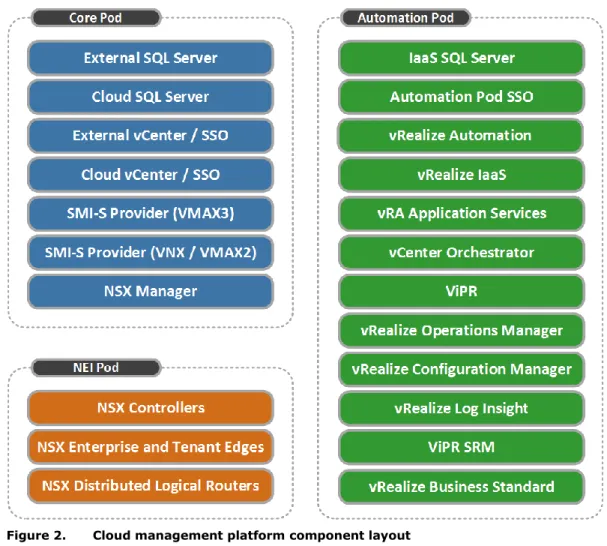
Figure 2 shows how the components of the management stack are distributed among the management pods.
Figure 2. Cloud management platform component layout Core Pod
The Core Pod provides the base set of resources to establish the Federation Enterprise Hybrid Cloud solution services. It consists of:
External VMware vCenter Server™ (optional): This vCenter instance hosts only the Core Pod components and hardware. It is required when using the Distributed management model and may already exist, depending on customer resources.
Cloud VMware vCenter Server: This vCenter instance is used to manage the NEI and Automation components and hardware. If using the Collapsed management model it also hosts the Core Pod components and hardware. vRealize Automation uses this vCenter Server as its endpoint from which the appropriate vSphere ESXi clusters are reserved for use by vRealize Automation business groups.
Management platform resource types
Microsoft SQL Server: Hosts SQL Server databases used by the Cloud vCenter Server and VMware Update Manager™. It also hosts the VMware vCenter Site Recovery Manager™ database in a DR dual-site/dual vCenter topology.
Note: Figure 2 includes separate SQL Server virtual machines for the External and Cloud vCenter SQL Server databases. This provides maximum resilience. Placing both vCenter databases on the same SQL Server virtual machine in the Core Pod is also supported. The vRealize IaaS SQL Server database must be on its own SQL Server instance in the Automation Pod.
VMware NSX™/VMware vCloud® Networking and Security Manager™: Used to deploy and manage the Workload Pod and the management infrastructure virtual networks. EMC SMI-S Provider: Management infrastructure required for EMC ViPR deployment. The hardware hosting the Core Pod is not under cloud management, but the virtual machines it hosts provide the critical services for the cloud.
All of the virtual machines on the Core Pod are deployed on non-ViPR storage. The virtual machines can use existing SAN connected storage or any high-availability storage in the customer environment.
The Federation Enterprise Hybrid Cloud supports Fibre Channel (FC), iSCSI, and NFS storage from EMC VNX® storage systems for the Core Pod storage. Though not mandatory, FC connectivity is strongly recommended.
All storage should be RAID protected and all vSphere ESXi servers should be configured with EMC PowerPath/VE for automatic path management and load balancing.
Network Edge Infrastructure (NEI) Pod
The NEI Pod is used to host all of the north/south vCloud networking components and the security Edge components of the virtualized network. When NSX is used, it also hosts the NSX Controller appliances. This pod provides the convergence point for the physical and virtual networks.
Like the Core Pod, storage for this pod should be RAID protected and the Federation
recommends Fibre Channel connections. vSphere ESXi hosts should run EMC PowerPath®/VE for automatic path management and load balancing.
Automation Pod
The Automation Pod hosts all the virtual machines used for automating and managing the cloud infrastructure, except for services installed in the Core Pod. The Automation Pod supports the services responsible for functions such as the user portal, automated provisioning, monitoring, and metering.
The Automation Pod is managed by the Cloud vCenter Server instance; however it is dedicated to automation and management services. Therefore, the resources from this pod are not exposed to vRealize Automation business groups.
The Automation Pod does not share networks or storage resources with the workload clusters. Storage provisioning for the Automation Pod follows the same guidelines as the NEI Pod.
The distributed management model and collapsed management model are described in the following sections.
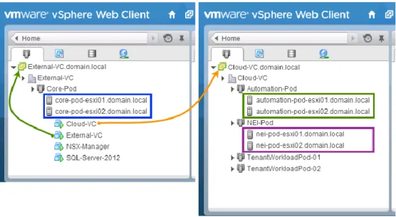
The distributed management model uses two separate vCenter instances and each management pod has its own distinct vSphere ESXi cluster. Therefore, it requires a minimum of seven hosts.
A higher level, External vCenter Server instance manages all server and virtual machine components for the Core Pod. While this vCenter instance can also be located on the cloud management platform Core Pod, it can also be located on a separate system for further levels of high availability.
The second Cloud vCenter Server instance located on the cloud management platform manages the NEI, Automation, and Workload Pods supporting the various business groups within the enterprise. This server acts as the vSphere end-point for vRealize Automation.
Figure 3 shows the default configuration of two vCenters where the first vCenter supports the Core Pod and the second vCenter supports the remaining cloud management pods and tenant resources.
Figure 3. Cloud management - distributed vSphere cluster model The distributed management model:
Enables Core Pod functionality and resources to be provided by a pre-existing vSphere instance within your environment.
Provides the highest level of resource separation (that is, host level) between the Core, Automation, and NEI Pods.
Places the NEI Pod ESXi cluster as the single intersection point between the physical and virtual networks configured within the solution, which eliminates the need to have critical networking components compete for resources as the solution scales and the demands of other areas of the cloud management platform increase.
Enhances the resilience of the solution because a separate vCenter server and SQL Server instance host the core cloud components.
Distributed management model
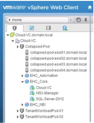
The collapsed management model uses a single vCenter server to host all Core, Automation, and NEI Pod components and the Workload Pods.
Each management pod is implemented as an individual vSphere resource group, which ensures that each pod receives the correct proportion of compute and network resources. It requires a minimum of three physical hosts.
Figure 4 shows an example of how the vSphere configuration might look with a collapsed management model.
Figure 4. Cloud management - collapsed vSphere cluster model The collapsed management model:
Provides the smallest overall management footprint for any given cloud size to be deployed.
Allows resource allocation between pods to be reconfigured with minimal effort. Allows high-availability overhead to be reduced by using a single cluster, but does not
alter the CPU, RAM, or storage required to manage the solution.
Given that a single vSphere cluster is used in the collapsed management model, a vSphere resource group is required for each Management Pod in order to ensure sufficient resources are reserved for each function. Use the guidelines in Table 2 as the starting point for balancing these resources appropriately.
Collapsed management model: Resource groups configuration Table 2.
Resource Core NEI Auto
CPU 20% 20% 60%
RAM 20% 5% 75%
Note: These figures are initial guidelines and should be monitored in each environment and fine-tuned accordingly. The percentages can be implemented, as shares, in whatever scale is Collapsed
management model
Resource pool considerations
required, when the percentage of shares assigned to each resource pool corresponds to the ratio of percentages in Table 2.
When operating in a collapsed management model, it may be necessary to configure network quality of service (QoS) to ensure .that each function has a guaranteed minimum level of bandwidth available. Table 3 shows the suggested initial QoS settings. These can be subsequently fine-tuned as appropriate to the environment.
Note: These values are suggestions based on the logical network Layout 1 in Chapter 6. As this layout is only a sample, you should collapse or divide these allocations according to the network topology you want to implement
Suggested network QoS settings Table 3.
Name VLAN DVS Shares DVS % Min QoS COS
vmk_ESXi_MGMT 100 500 5% 2
vmk_NFS 200 750 7.5% 4
vmk_iSCSI 300 750 7.5% 4
vmk_vMOTION 400 1400 14% 1
DPG_Core 500 500 5% 2
DPG_NEI 600 500 5% 2
DPG_Automation 700 500 5% 2
DPG_Tenant_Uplink 800 2000 20% 0
VXLAN_Transport 900 * * *
Avamar_Target (Optional) 1000 ** ** **
DPG_AV_Proxies (Optional) 1100 600 6% 0
ESG_DLR_Transit Virtual Wire 1250 12.5% 0
Workload Virtual Wire 1250 12.5% 0
*This is a VXLAN_Transport VLAN. The shares are associated with the virtual wire networks that use the transport VLAN.
**Physical network only. No shares required.
Use the following key criteria to decide which management model is most suited for your environment:
Reasons to select the distributed model
You want to use the existing infrastructure to provide the resources that will host the Core Pod.
You require the highest level of resource separation (that is, host level) between the Core, Automation, and NEI Pods.
You want to minimize the intersection points for north/south traffic to just the hosts that serve as the NEI Pod.
You want to maximize the resilience of the solution by using a separate vCenter server and SQL Server instance to host the core cloud components.
Network quality of service considerations
Deciding on the management model
Reasons to select the collapsed model
You want to deploy the smallest management footprint for any given cloud size. You want resource allocation between pods to be reconfigurable with minimal effort.
This chapter presents the following topics:
Overview ... 24 Single-site networking considerations ... 24 Single-site storage considerations ... 25 Recovery of cloud management platform ... 27 Backup of single-site/single vCenter enterprise hybrid cloud ... 27
This chapter describes networking and storage considerations for a single-site/single vCenter topology in the Federation Enterprise Hybrid Cloud solution.
The single-site/single vCenter Federation Enterprise Hybrid cloud topology should be used when restart or recovery of the cloud to another data center is not required. It can also be used as the base deployment on top of which you may layer the dual-site/single vCenter or dual-site/dual vCenter topology at a later time.
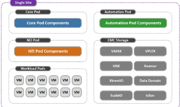
Figure 5 shows the single-site/single vCenter architecture for the Federation Enterprise Hybrid Cloud solution including the required sets of resources separated by pod.
Figure 5. Federation Enterprise Hybrid Cloud single-site architecture
In a single-site topology, all NSX Controller components reside in the NEI Pod. NSX best practice recommends that each controller be placed on separate physical hosts. When NSX is the chosen networking technology, this solution uses three NSX controllers.
When using the Federation Enterprise Hybrid Cloud Sizing tool, appropriate consideration should be given to the choice of server specification for the NEI Pod to ensure efficient use of hardware resources, because a three-server minimum will be enforced.
VMware Anti-Affinity Rules should be used to ensure that the NSX controllers reside on different hosts in optimum conditions.
When to use the single-site topology
Architecture
NSX controller placement
This Federation Enterprise Hybrid Cloud solution presents storage in the form of storage service offerings that greatly simplify virtual storage provisioning.
The storage service offerings are based on ViPR virtual pools, which are tailored to meet the performance requirements of general IT systems and applications. Multiple storage system virtual pools, consisting of different disk types, are configured and brought under ViPR management.
ViPR presents the storage to the enterprise hybrid cloud as virtual storage pools, abstracting the underlying storage details and enabling provisioning tasks to be aligned with the
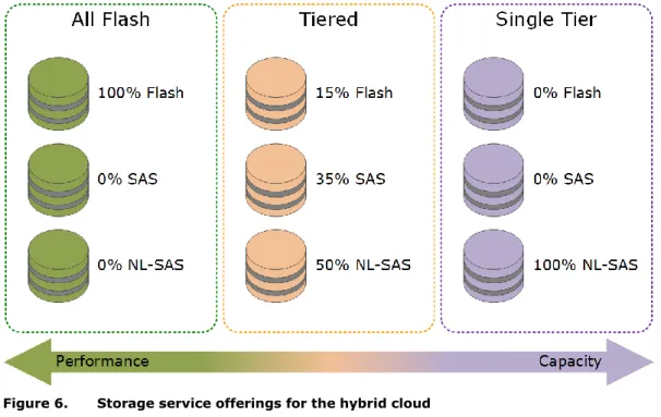
application’s class of service. Each ViPR virtual pool representing a storage service offering can be supported or backed by multiple storage pools of identical performance and capacity. This storage service offering concept is summarized in Figure 6.
Figure 6. Storage service offerings for the hybrid cloud
Note: The storage service offerings in Figure 6 are suggestions only. Storage service offerings can be configured and named as appropriate to reflect their functional use.
The storage service examples in Figure 6 suggest the following configurations: All Flash: Can be provided by either EMC XtremIO™ or VNX as all-flash storage. Tiered: Provides VNX or VMAX block or file-based VMFS or NFS storage devices and is
supported by multiple storage pools using EMC Fully Automated Storage Tiering for Virtual Pools (FAST® VP) and EMC Fully Automated Storage Tiering (FAST®) Cache. Single Tier: Provides EMC VNX block- or file-based VMFS or NFS storage and is
supported by multiple storage pools using a single storage type of NL-SAS in this example.
We suggest these storage service offerings only to highlight what is possible in a Federation Enterprise Hybrid Cloud environment. The full list of supported platforms includes:
EMC VMAX EMC VNX Storage design
EMC XtremIO EMC ScaleIO® EMC VPLEX EMC RecoverPoint
Isilon® (Workload use only)
As a result many other storage service offerings can be configured to suit business and application needs, as appropriate.
Note: The Federation recommends that you follow the best practice guidelines when deploying any of the supported platform technologies. The Federation Enterprise Hybrid Cloud does not require any variation from these best practices.
vRealize Automation provides the framework to associate one or more classes of storage with each line of business so that they can be consumed through the service catalog. Initially, physical storage pools are configured on the storage system and made available to ViPR where they are configured into their respective virtual pools. At provisioning time, LUNs or file systems are configured from these virtual pools and presented to vSphere as VMFS or NFS datastores. The storage is then discovered by vRealize Automation and made available for assignment to business groups within the enterprise.
This storage service offering approach greatly simplifies the process of storage
administration. Instead of users having to configure the placement of individual virtual machine disks (VMDKs) on different disk types such as serial-attached storage (SAS) and FC, they simply select the appropriate storage service level required for their business need. Virtual disks provisioned on FAST VP storage benefit from the intelligent data placement. While frequently accessed data is placed on disks with the highest level of service, less frequently used data is migrated to disks reflecting that service level.
When configuring virtual machine storage, a business group administrator can configure blueprints to deploy virtual machines onto any of the available storage service levels. In the example in Figure 7, a virtual machine can be deployed with a blueprint including a SQL Server database, to a storage service offering named Prod-2, which was designed with the performance requirements of such an application in mind.
Figure 7. Blueprint storage configuration in vRealize Automation
The devices for this SQL Server database machine have different performance requirements, but rather than assigning different disk types to each individual drive, each virtual disk can be configured on the Prod-2 storage service offering. This allows the underlying FAST technology to handle the best location for each individual block of data across the tiers. The Storage
vRealize Automation storage reservation policy ensures that the VMDKs are deployed to the appropriate storage.
The storage presented to vRealize Automation can be shared and consumed across the various business groups using the capacity and reservation policy framework in vRealize Automation.
Storage is provisioned to the Workload vSphere clusters in the environment using the
Provision Cloud Storage catalog item that can provision VNX, VMAX, XtremIO, ScaleIO, and VPLEX Local storage to single-site topology workload clusters.
The workflow interacts with both ViPR and vRealize Automation to create the storage, present it to the chosen vSphere cluster and add the new volume to the relevant vRealize Storage Reservation Policy.
vSphere clusters are made eligible for storage provisioning by tagging them with vRealize Automation custom properties that define them as Unprotected clusters, that is, that they are not involved in any form of inter-site replication relationship. This tagging is done during the installation and preparation of vSphere clusters for use by the Federation Enterprise Hybrid Cloud using the Unprotected Cluster Onboarding workflows provided as part of the Federation Enterprise Hybrid Cloud self-service catalog.
Note: Virtual machines on the cluster may still be configured to use backup as a service, as shown in Chapter 7.
As local-only vSphere clusters can also exist in continuous availability and DR topologies, this process ensures that only the correct type of storage is presented to the single-site vSphere clusters and no misplacement of virtual machines intended for inter-site protection occurs.
For block-based provisioning, ViPR virtual arrays should not contain more than one protocol. For Federation Enterprise Hybrid Cloud this means that ScaleIO storage and FC block storage must be provided via separate virtual arrays.
Recovery of the management platform does not apply to a single-site topology, because there is no target site to recover to.
The primary option for backup in a single-site/single vCenter topology is the Standard Avamar configuration, though the Redundant Avamar/single vCenter configuration may also be used to provide additional resilience. Both options are described in Chapter 7.
. Storage
provisioning
ViPR virtual pools
Single-site topology
Single-site/single vCenter topology backup
This chapter presents the following topics:
Overview ... 29 Standard dual-site/single vCenter topology ... 29 Continuous availability dual-site/single vCenter topology ... 30 Continuous availability network considerations ... 31 VPLEX Witness ... 35 VPLEX topologies ... 36 Continuous availability storage considerations ... 43 Recovery of cloud management platform ... 46 Backup in dual-site/single vCenter enterprise hybrid cloud ... 46
This chapter describes networking and storage considerations for a dual-site/single vCenter topology in the Federation Enterprise Hybrid Cloud solution.
The dual-site/single vCenter Federation Enterprise Hybrid Cloud topology may be used when restart of the cloud to another data center is required. It should only be used in either of the following two scenarios:
Two sites are present that require management via a single vCenter instance and a single Federation Enterprise Hybrid Cloud management platform/portal.
This model has no additional storage considerations beyond the single-site/single vCenter model because each site has completely independent storage.
This model employs a second NEI Pod on the second site to ensure north/south network traffic egresses the second site in the most efficient manner. The local NEI Pod will host the Edge gateway services for its respective site.
Note: In this case, the scope of the term site is at the user’s discretion. It could be taken to mean separate individual geographical locations, or could also mean independent islands of infrastructure in the same geographical location such as independent VCE Vblock® platforms.
Continuous availability is required. This topology also requires that: EMC VPLEX storage is available.
Stretched Layer 2 VLANs are permitted or the networking technology chosen supports VXLANs.
The latency between the two physical data center locations is less than 10 ms.
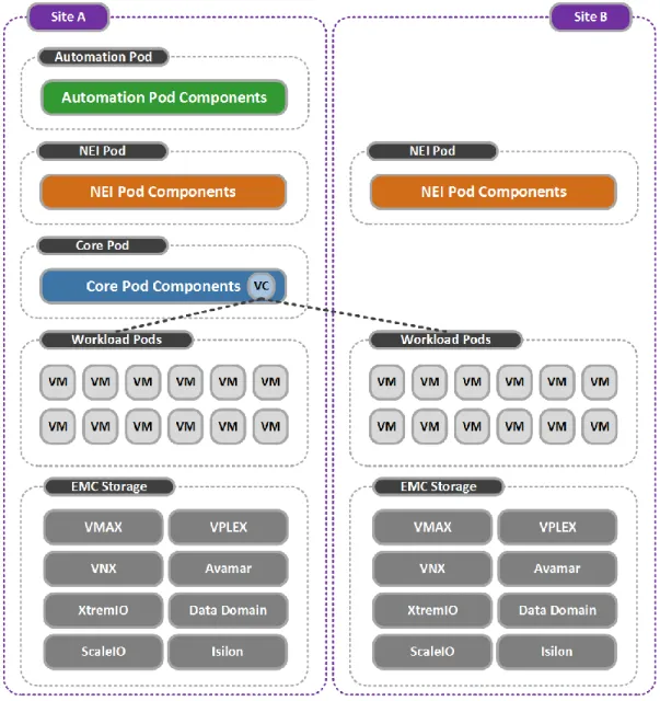
The standard dual-site/single vCenter Federation Enterprise Hybrid Cloud topology controls two sites, each with independent islands of infrastructure using a single vCenter instance and Federation Enterprise Hybrid Cloud management stack/portal.
This architecture provides a mechanism to extend an existing Federation Enterprise Hybrid Cloud by adding additional independent infrastructure resources to an existing cloud, when resilience of the management platform itself is not required. Figure 8 shows the architecture used for this topology option.
When to use the dual-site/single vCenter topology
Figure 8. Federation Enterprise Hybrid Cloud standard dual-site/single vCenter architecture
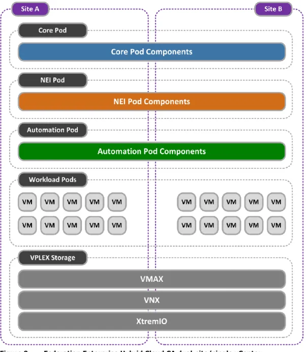
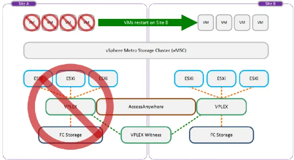
The continuous availability (CA) dual-site/single vCenter Federation Enterprise Hybrid Cloud topology is an extension of the standard dual-site/single vCenter model that stretches the infrastructure across both sites, using VMware vSphere Metro Storage Clusters (vMSC), vSphere HA, and VPLEX in Metro configuration.
This topology enables multi-site resilience across two sites with automatic restart of both the management platform and workload virtual machines on the surviving site. Figure 9 shows the architecture used for this topology option.
Figure 9. Federation Enterprise Hybrid Cloud CA dual-site/single vCenter architecture
In a CA dual-site/single vCenter topology, all NSX Controller components reside in the NEI Pod. NSX best practice recommends that each controller be placed on separate physical hosts. When NSX is the chosen networking technology, this solution uses a minimum of three NSX controllers.
When using the Federation Enterprise Hybrid Cloud Sizing tool, appropriate consideration should be given to the choice of server specification for the NEI Pod to ensure efficient use of hardware resources, given that a three-server minimum will be enforced.
NSX Controller placement
Two out of the three NSX controllers must be operating for the NSX control plane to be available. The following recommendations are made regarding controller placement:
VMware Anti-Affinity Rules should be used to ensure that the NSX controllers reside on different hosts in optimum conditions.
Two NSX controllers should be placed on one site and one NSX controller placed on the other site. This should be achieved using a combination of host DRS groups, virtual machine DRS group and virtual machine DRS rules set to ensure that virtual machines in the virtual machine DRS groups ‘should run’ on the relevant host DRS groups. VMware HA should be configured to enable NSX controllers restart.
If vSphere Distributed Switches are used in the CA dual-site/single vCenter topology, then all networks must be backed by stretched Layer 2 VLANs.
Use of NSX of vSphere or vCloud Networking and Security enables you to use VXLANs backed by a Layer 3 DCI.
Data centers that are connected together over a metro link can use either Layer 2 bridged VLAN connectivity or Layer 3 routed IP connectivity.
Both Data Center Interconnect (DCI) options have advantages and disadvantages. However, new standards and technologies, such as Virtual Extensible LAN (VXLAN), address most of the disadvantages.
Traditional disadvantages of Layer 2 DCI
The risks related to Layer 2 extensions between data centers mirror some of the limitations faced in traditional Ethernet broadcast domains.
The limiting factor is the scalability of a single broadcast domain. A large number of hosts and virtual machines within a broadcast domain, all of which contend for shared network resources, can result in broadcast storms. The results of broadcast storms are always to the detriment of network availability, adversely affecting application delivery and ultimately leading to a poor user experience. This can affect productivity.
As the CA architecture is stretched across both data centers, a broadcast storm could cause disruption in both the primary and secondary data centers.
Multiple Layer 2 interconnects create additional challenges for stretched networks. If unknown broadcast frames are not controlled, loops in the Layer 2 extension can form. This can also cause potential disruption across both data centers, resulting in network downtime and loss of productivity.
If used, the Spanning Tree Protocol (STP) needs to be run and carefully managed to control loops across the primary and secondary site interconnecting links.
Loop avoidance and broadcast suppression mechanisms are available to the IT professional, but must be carefully configured and managed.
Traditional advantages of Layer 2 DCI
The greatest advantage of Layer 2 DCI is the IP address mobility of physical and virtual machines across both data centers. This simplifies DR in the event of a failure in the primary data center.
Note: Layer 2 connectivity is often necessary for applications where heartbeats and clustering techniques are used across multiple hosts. In some cases, technologies might not be able to span Layer 3 boundaries.
Stretched networks and network technology choice Data Center Interconnect
Traditional disadvantages of Layer 3 DCI
If an infrastructure failure occurs at the primary site, a machine migrated to the secondary data center must be reconfigured to use an alternate IP addressing scheme. This can be more time consuming and error prone than having a high-availability deployment across a single Layer 2 domain.
Inter-site machine clustering may not be supported over a Layer 3 boundary, which can be either multicast or broadcast based.
Traditional advantages of Layer 3 DCI
Layer 3 DCI does not use extended broadcast domains or require the use of STP. Therefore, there is greater stability of the production and services networks across both primary and secondary data centers.
Note: The data center interconnect physical link is subject to the availability of the local telecommunications service provider and the business requirement of the enterprise. Continuous availability DCI networking solution
The network topology used in the CA for Federation Enterprise Hybrid Cloud solution incorporates the advantages of both Layer 2 and Layer 3 DCI topologies. Layer 2 requirements such as resource and management traffic are handled by the VXLAN
implementation enabled by NSX. This offers the advantage of IP mobility across both sites by placing the resource and management traffic on spanned VXLAN segments. It also eliminates the complexity of STP and performance degradation that large broadcast domains can introduce.
VXLANs can expand the number of Layer 2 domains or segments beyond the 802.1q limit of 4,096 VLANs to a theoretical limit of 16 million. VXLANs can also extend the Layer 2
environment over Layer 3 boundaries.
An underlying Layer 3 data center interconnect runs a dynamic route distribution protocol with rapid convergence characteristics such as Open Shortest Path First (OSPF). OSPF routing metrics route the ingress traffic to the primary data center. If the primary data center is unavailable, the OSPF algorithm automatically converges routes to the secondary data center. This is an important advantage compared to using a traditional Layer 2 DCI and Layer 3 DCI solution in isolation.
Note: NSX also supports Border Gateway Protocol (BGP) and Intermediate System to Intermediate System (IS-IS) route distribution protocols.
In a collapsed management model, all clusters are part of the same vCenter instance and therefore can all be configured to use the security and protection features offered by the same NSX Manager instance. If this is not a requirement for Core Pod, then a stretched Layer 2 network may also be used.
In a distributed management model, two vCenter instances are used. Given the 1:1
relationship between a vCenter instance and NSX Manager, a second NSX manager instance would be required if the Core Pod is to use the security and protection NSX provisioned networks. Given the small number of virtual machines present in the external vCenter, it may be appropriate to consider a stretched Layer 2 VLAN for this network if the second NSX manager instance is deemed unnecessary.
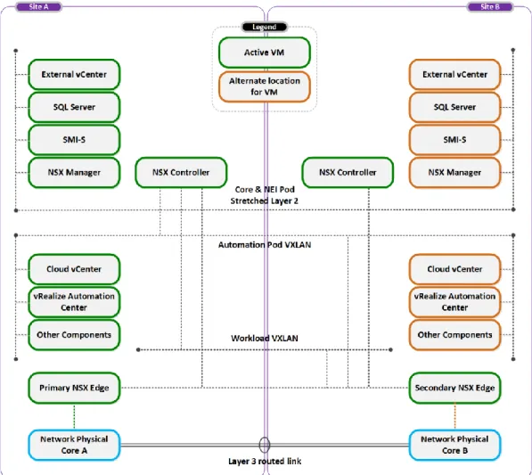
Figure 10 shows one possible scenario where two data centers are connected using both a Layer 2 and a routed Layer 3 IP link and how the Core, NEI, Automation, and Workload segments could be provisioned.
Figure 10. Continuous availability data center interconnect example In this scenario, the following properties are true:
vSphere ESXi stretched clusters are utilized to host the Core, Automation, NEI, and Workload virtual machines. This, with vSphere HA, enables virtual machines to be automatically restarted on the secondary site, if the primary site fails.
The Core Pod virtual machines are connected to a stretched VLAN. This prevents the need for a second NSX manager machine.
The NSX controllers (NEI Pod) are connected to the same stretched VLAN as the Core Pod virtual machines.
The Automation Pod virtual machines are connected to an NSX logical network, backed by VXLAN and available across both sites.
The Workload Pod virtual machines are connected to a NSX logical network, backed by VXLAN and available across both sites.
VXLAN encapsulated traffic must be able to travel between vSphere ESXi hosts at both sites.
One or more NSX Edge Services Gateways (ESGs) are deployed at each site to control traffic flow between the virtual and physical network environments.
Note: NSX supports three modes of replication for VXLAN traffic unicast, multicast and hybrid. Unicast mode enables VXLAN traffic to be carried across Layer 3 boundaries without assistance from the underlying physical network. If vCNS is used instead of NSX, then the physical network must support multicast.
vSphere HA, in combination with VPLEX and VPLEX Witness, enables the cloud-management platform virtual machines to restore the cloud-management service on the secondary site in the event of a total loss of the primary data center. In this scenario, the virtual machines automatically move to and operate from vSphere ESXi nodes residing in the secondary data center.
Edge Services Gateway considerations
All workload virtual machines should use NSX logical networks connected to a Distributed Logical Router (DLR). The DLR can provide the same default gateway to a virtual machine, whether it is running at the primary or secondary site.
DLRs should be connected to at least one ESG at each site and a dynamic route distribution protocol (such as OSPF and others supported by NSX) should be used to direct traffic flow. We recommend that you use both NSX High Availability and High Availability in conjunction with host DRS groups, virtual machine DRS groups and virtual machine DRS Affinity rules to ensure that DLR virtual machines run on the correct site in optimum conditions.
This solution has all the advantages of traditional Layer 2 and Layer 3 solutions. It provides increased flexibility and scalability by implementing VXLANs, and benefits from increased stability by not extending large broadcast domains across the VPLEX Metro.
VPLEX Witness is an optional component deployed in customer environments where the regular preference rule sets are insufficient to provide seamless zero or near-zero recovery time objective (RTO) storage availability in the event of site disasters or VPLEX cluster and inter-cluster failures.
Without VPLEX Witness, all distributed volumes rely on configured rule sets to identify the preferred cluster in the event of a cluster partition or cluster/site failure. However, if the preferred cluster fails (for example, as a result of a disaster event), VPLEX is unable to automatically enable the surviving cluster to continue I/O operations to the affected distributed volumes. VPLEX Witness is designed to overcome this.
The VPLEX Witness server is deployed as a virtual appliance running on a customer’s vSphere ESXi host that is deployed in a failure domain separate from both of the VPLEX clusters. The third fault domain must have power and IP isolation from both the Site A and Site B fault domains, which host the VPLEX Metro Clusters.
This eliminates the possibility of a single fault affecting both the cluster and VPLEX Witness. VPLEX Witness connects to both VPLEX clusters over the management IP network. By reconciling its own observations with the information reported periodically by the clusters, VPLEX Witness enables the clusters to distinguish between inter-cluster network partition failures and cluster failures, and to automatically resume I/O operations in these situations. Figure 11 shows an example of a high-level deployment of VPLEX Witness and how it can augment an existing static preference solution. The VPLEX Witness server resides in a fault domain separate from the VPLEX clusters on Site A and Site B.
Figure 11. High-level deployment of EMC VPLEX Witness
VMware classifies the stretched VPLEX Metro cluster configuration with VPLEX into the following categories:
Uniform host access configuration with VPLEX host Cross-Connect—vSphere ESXi hosts in a distributed vSphere cluster have a connection to the local VPLEX system and paths to the remote VPLEX system. The remote paths presented to the vSphere ESXi hosts are stretched across distance.
Non-uniform host access configuration without VPLEX host Cross-Connect— vSphere ESXi hosts in a distributed vSphere cluster have a connection only to the local VPLEX system.
Use the following guidelines to help you decide which topology suits your environment: Uniform (Cross-Connect) is typically used where:
Inter-site latency is less than 5ms.
Stretched SAN configurations are possible.
Non-Uniform (without Cross-Connect) is typically used where: Inter-site latency is between 5 ms and 10 ms.
Stretched SAN configurations are not possible.
EMC GeoSynchrony® supports the concept of a VPLEX Metro cluster with Cross-Connect. This configuration provides a perfect platform for a uniform vSphere stretched-cluster deployment. VPLEX with host Cross-Connect is designed for deployment in a metropolitan-type topology with latency that does not exceed 5 ms round-trip time (RTT).
vSphere ESXi hosts can access a distributed volume on the local VPLEX cluster and on the remote cluster in the event of a failure. When this configuration is used with VPLEX Witness, vSphere ESXi hosts are able to survive through multiple types of failure scenarios. For example, in the event of a VPLEX cluster or back-end storage array failure, the vSphere ESXi hosts can still access the second VPLEX cluster with no disruption in service. Deciding on
VPLEX topology
Uniform host access
configuration with VPLEX host Cross-Connect
In the unlikely event that the preferred site fails, VPLEX Witness intervenes and ensures that access to the surviving cluster is automatically maintained. In this case, vSphere HA
automatically restarts all affected virtual machines.
Figure 12 shows that all ESXi hosts are connected to the VPLEX clusters at both sites. This can be achieved in a number of ways:
Merge switch fabrics by using Inter-Switch Link (ISL) technology used to connect local and remote SANs.
Connect directly to the remote data center fabric without merging the SANs.
Figure 12. Deployment model with VPLEX host Cross-Connect
This type of deployment is designed to provide the highest possible availability for a Federation Enterprise Hybrid Cloud environment. It can withstand multiple failure scenarios including switch, VPLEX, and back-end storage at a single site with no disruption in service. For reasons of performance and availability, the Federation recommends that separate host bus adapters be used for connecting to local and remote switch fabrics.
Note: VPLEX host Cross-Connect is configured at the host layer only and does not imply any cross connection of the back-end storage. The back-end storage arrays remain locally connected to their respective VPLEX clusters.
From the host perspective, in the uniform deployment model with VPLEX host
Cross-Connect, the vSphere ESXi hosts are zoned to both the local and the remote VPLEX clusters. Figure 13 displays the VPLEX storage views for a host named DRM-ESXi088, physically located in Site A of our environment.
Here the initiators for the host are registered and added to both storage views with the distributed device being presented from both VPLEX clusters.
Figure 13. VPLEX storage views with host Cross-Connect
This configuration is transparent to the vSphere ESXi host. The remote distributed volume is presented as an additional set of paths.
Figure 14 shows the eight available paths that are presented to host DRM-ESXi088, for access to the VPLEX distributed volume hosting the datastore named CC-Shared-M3. The serial numbers of the arrays are different because four of the paths are presented from the first VPLEX cluster and the remaining four are presented from the second.
Figure 14. Datastore paths in a VPLEX with host Cross Connect configuration PowerPath/VE autostandby mode
Neither the host nor the native multipath software can by themselves distinguish between local and remote paths. This poses a potential impact on performance if remote paths are used for I/O in normal operations because of the cross-connect latency penalty.
PowerPath/VE provides the concept of autostandby mode, which automatically identifies all remote paths and sets them to standby (asb:prox is the proximity-based autostandby algorithm). This feature ensures that only the most efficient paths are used at any given time.
PowerPath/VE groups paths internally by VPLEX cluster. The VPLEX cluster with the lowest minimum path latency is designated as the local/preferred VPLEX cluster, while the other VPLEX cluster within the VPLEX Metro system is designated as the remote/non-preferred cluster.
A path associated with the local/preferred VPLEX cluster is put in active mode, while a path associated with the remote/non-preferred VPLEX cluster is put in autostandby mode. This forces all I/O during normal operations to be directed towards the local VPLEX cluster. If a failure occurs where the paths to the local VPLEX cluster are lost, PowerPath/VE activates the standby paths and the host remains up and running on the local site, while accessing storage on the remote site.
The non-uniform host configuration can be used for a Federation Enterprise Hybrid Cloud deployment if greater distances are required. The supported latency of this configuration requires that the round-trip time be within 5 ms to comply with VMware HA requirements. Without the cross-connect deployment, vSphere ESXi hosts at each site have connectivity to only that sites VPLEX cluster.
Figure 15 shows that hosts located at each site have connections to only their respective VPLEX cluster. The VPLEX clusters have a link between them to support the VPLEX Metro configuration, and the VPLEX Witness is located in a third failure domain.
Figure 15. VPLEX architecture without VPLEX Cross-Connect
The major benefit of this deployment option is that greater distances can be achieved in order to protect the infrastructure. With the EMC VPLEX AccessAnywhereTM feature, the non-uniform deployment offers the business another highly resilient option that can withstand various types of failures including front-end and back-end single path failure, single switch failure, and single back-end array failure.
Figure 16 shows the storage views from VPLEX cluster 1 and cluster 2. In the example non-uniform deployment, hosts DRM-ESXi077 and DRM-ESXi099 represent hosts located in different data centers. They are visible in their site-specific VPLEX cluster’s storage view. With Non-uniform host
access
configuration without VPLEX Cross-Connect
AccessAnywhere, the hosts have simultaneous write access to the same distributed device, but only via the VPLEX cluster on the same site.
Figure 16. VPLEX Storage views without VPLEX Cross-Connect
Figure 17 shows the path details for one of the hosts in a stretched cluster that has access to the datastores hosted on the VPLEX distributed device. The World Wide Name (WWN) on the Target column shows that all paths to that distributed device belong to the same VPLEX cluster. PowerPath/VE has also been installed on all of the hosts in the cluster, and it has automatically set the VPLEX volume to the adaptive failover mode. The autostandby feature is not used in this case because all the paths to the device are local.
Figure 17. vSphere Datastore Storage paths without VPLEX Cross-Connect
With vSphere HA, the virtual machines are also protected against major outages, such as network partitioning of the VPLEX WAN link or an entire site failure. In order to prevent any unnecessary down time, the Federation recommends that the virtual machines reside on the site that would win ownership of the VPLEX distributed volume in the event of such a partitioning occurring.
The solution uses VMware Host Distributed Resource Scheduler (DRS) groups to subdivide the vSphere ESXi hosts in each workload and management cluster into groupings of hosts corresponding to their respective sites. It does this by defining two VMware host DRS groups in the format SiteName_Hosts where the site names of both sites are defined during the installation of the Federation Enterprise Hybrid Cloud foundation package.
Site affinity for virtual machines
VMware virtual machine DRS groups are also created in the format Sitename_VMs during the preparation of the ESXi cluster for continuous availability.
Storage reservation polices (SRPs) created by the Federation Enterprise Hybrid Cloud storage as service workflows are automatically named to indicate the preferred site in which that storage type is run.
Note: In this case, the preferred setting means that in the event of a failure that results in the VPLEX units being unable to communicate, that this site will be the one that continues to provide read/write access to the storage.
During deployment of a virtual machine though the vRealize portal, the user is asked to choose from a list of storage reservation policies. Federation Enterprise Hybrid Cloud custom workflows use this information to place the virtual machine on a vSphere ESXi cluster with access to the required storage type and placing the virtual machine into the appropriate virtual machine DRS group.
Virtual machines to host DRS rules are then used to bind virtual machines to the preferred site by configuring the SiteName_VMs virtual machine DRS group with a setting of “should run” on the respective SiteName_Hosts host DRS group. This ensures virtual machines run on the required site, while allowing them the flexibility of failing over if the infrastructure on that site becomes unavailable.
Figure 18 shows how the virtual machine DRS groups and affinity rules might look in a sample configuration.
Figure 18. Sample view of Site Affinity DRS Group and Rule configuration
Note: The values “SiteA” and “SiteB” shown in both Figure 18 and Figure 19 can and should be replaced with meaningful site names in a production environment. They must correlate with the site name values entered during the Federation Enterprise Hybrid Cloud Foundation package initialization for site affinity to work correctly.
Figure 19 shows a simple example of two scenarios where virtual machines are deployed to a vMSC and how the logic operates to place those virtual machines on their preferred sites.
Figure 19. Deploying virtual machines with site affinity Scenario 1: Deploy VM1 with affinity to Site A
This scenario describes deploying a virtual machine (VM1) with affinity to Site A:
1. During virtual machine deployment, the user chooses a storage reservation policy named SiteA_Preferred_CA_Enabled.
2. This storage reservation policy choice filters the cluster choice to only those clusters with that reservation policy. In this case cluster 1.
3. Based on the selected storage reservation policy, Federation Enterprise Hybrid Cloud workflows programmatically determine that Site A is the preferred location, and therefore locates the virtual machine DRS affinity group corresponding with Site A, namely SiteA_VMs.
4. The expected result is:
a. VM1 is deployed into SiteA_VMs, residing on host CL1-H1 or CL1H2.
b. VM1 is deployed onto a datastore from the SiteA_Preferred_CA_Enabled storage reservation policy, for example:
VPLEX_Distributed_LUN_SiteA_Preferred_01 or VPLEX_Distributed_LUN_SiteA_Preferred_02
Scenario 2: Deploy VM2 with affinity to Site B
This scenario describes deploying a virtual machine (VM2) with affinity to Site B:
1. During virtual machine deployment, the user chooses a storage reservation policy named SiteB_Preferred_CA_Enabled.
2. This storage reservation policy choice filters the cluster choice to only those clusters with that reservation policy. In this case cluster 1.