Technical Specification
MEF 10.2
Ethernet Services Attributes Phase 2
Disclaimer
The information in this publication is freely available for reproduction and use by any recipient and is believed to be accurate as of its publication date. Such information is subject to change without notice and the Metro Ethernet Forum (MEF) is not responsible for any errors. The MEF does not assume responsibility to update or correct any information in this publication. No representation or warranty, expressed or implied, is made by the MEF concerning the completeness, accuracy, or applicability of any information contained herein and no liability of any kind shall be assumed by the MEF as a result of reliance upon such information.
The information contained herein is intended to be used without modification by the recipient or user of this document. The MEF is not responsible or liable for any modifications to this document made by any other party.
The receipt or any use of this document or its contents does not in any way create, by implication or otherwise:
a) any express or implied license or right to or under any patent, copyright, trademark or trade secret rights held or claimed by any MEF member company which are or may be associated with the ideas, techniques, concepts or expressions contained herein; nor b) any warranty or representation that any MEF member companies will announce any
product(s) and/or service(s) related thereto, or if such announcements are made, that such announced product(s) and/or service(s) embody any or all of the ideas, technologies, or concepts contained herein; nor
c) any form of relationship between any MEF member companies and the recipient or user of this document.
Implementation or use of specific Metro Ethernet standards or recommendations and MEF specifications will be voluntary, and no company shall be obliged to implement them by virtue of participation in the Metro Ethernet Forum. The MEF is a non-profit international organization accelerating industry cooperation on Metro Ethernet technology. The MEF does not, expressly or otherwise, endorse or promote any specific products or services.
Table of Contents
1. Abstract ... 1
2. Terminology... 1
3. Scope... 5
4. Compliance Levels ... 6
5. Introduction ... 6
6. Ethernet Virtual Connection Service Attributes ... 7
6.1 Ethernet Virtual Connection Type Service Attribute ... 8
6.1.1 Point-to-Point EVC ... 8
6.1.2 Multipoint EVCs ... 8
6.1.2.1 Multipoint-to-Multipoint EVC ... 8
6.1.2.2 Rooted-Multipoint EVC ... 9
6.2 EVC ID Service Attribute... 9
6.3 UNI List Service Attribute ... 10
6.4 Maximum Number of UNIs Service Attribute ... 10
6.5 Service Frame Delivery Service Attributes ... 10
6.5.1 Types of Service Frame ... 10
6.5.1.1 Unicast Service Frame ... 10
6.5.1.2 Multicast Service Frame ... 10
6.5.1.3 Broadcast Service Frame ... 10
6.5.1.4 Layer 2 Control Protocol Service Frame ... 10
6.5.1.5 Data Service Frame ... 11
6.5.2 Service Frame Disposition ... 11
6.5.3 Service Frame Transparency ... 12
6.6 CE-VLAN Tag Preservation Service Attributes ... 12
6.6.1 CE-VLAN ID Preservation Service Attribute ... 12
6.6.2 CE-VLAN CoS Preservation Service Attribute ... 13
6.7 EVC Layer 2 Control Protocol Processing Service Attribute ... 13
6.8 Class of Service Identifier Service Attribute ... 14
6.8.1 Class of Service Identifier Based on EVC ... 14
6.8.2 Class of Service Identifier Based on Priority Code Point Field ... 15
6.8.3 Class of Service Identifier Based on DSCP ... 15
6.8.4 Class of Service Identifier Based on Layer 2 Control Protocol ... 15
6.9 EVC Related Performance Service Attributes ... 15
6.9.1 Frame Delay Performance for a Point-to-Point EVC ... 16
6.9.2 One-way Frame Delay Performance for an EVC ... 17
6.9.3 Inter-Frame Delay Variation Performance for a Point-to-Point EVC ... 20
6.9.4 Inter-Frame Delay Variation Performance for an EVC ... 21
6.9.5 One-way Frame Loss Ratio Performance for a Point-to-Point EVC ... 24
6.9.6 One-way Frame Loss Ratio Performance for an EVC ... 24
6.9.7 Availability Performance for a Point-to-Point EVC ... 25
6.9.8 Availability Performance for a Multipoint EVC ... 28
7. UNI and EVC per UNI Service Attributes ... 29
7.1 UNI Identifier Service Attribute ... 30
7.2 Physical Layer Service Attribute ... 30
7.3 MAC Layer Service Attribute ... 30
7.4 UNI Maximum Transmission Unit Size Service Attribute ... 31
7.5 Service Multiplexing Service Attribute ... 31
7.6 Identifying an EVC at the UNI ... 31
7.6.1 Customer Edge VLAN ID ... 31
7.6.2 UNI EVC ID Service Attribute ... 32
7.7 CE-VLAN ID/EVC Map Service Attribute... 32
7.7.1 Basic Concept ... 32
7.7.2 CE-VLAN ID Significance ... 33
7.7.3 Describing the Contents of the CE-VLAN ID/EVC Map ... 34
7.8 Maximum Number of EVCs Service Attribute ... 34
7.9 Bundling Service Attribute ... 34
7.10 All to One Bundling Service Attribute ... 35
7.11 Bandwidth Profiles Service Attributes ... 36
7.11.1 Standard Bandwidth Profile Parameters and Algorithm ... 36
7.11.2 Ingress Bandwidth Profiles Service Attributes ... 39
7.11.2.1 Ingress Bandwidth Profile per Ingress UNI Service Attribute ... 39
7.11.2.2 Ingress Bandwidth Profile per EVC Service Attribute ... 39
7.11.2.3 Ingress Bandwidth Profile per Class of Service Identifier Service Attribute ... 40
7.11.2.4 Simultaneous Application of the Ingress Bandwidth Profile Application Models ... 40
7.11.2.5 Service Frame Disposition ... 41
7.11.3 Egress Bandwidth Profiles Service Attributes ... 41
7.11.3.1 Egress Bandwidth Profile per Egress UNI Service Attribute ... 42
7.11.3.2 Egress Bandwidth Profile per EVC Service Attribute ... 43
7.11.3.3 Egress Bandwidth Profile per Class of Service Identifier Service Attribute ... 44
7.11.3.4 Simultaneous Application of the Egress Bandwidth Profile Application Models ... 44
7.12 Security ... 44
7.13 UNI Layer 2 Control Protocol Processing Service Attribute ... 44
7.13.1 Discard ... 44
7.13.2 Peer ... 45
7.13.3 Pass to EVC ... 45
7.13.4 Peer and Pass to EVC ... 45
8. Ethernet Service Framework ... 45
8.1 Ethernet Service Types ... 46
8.2 Service Attributes ... 46
8.3 Service Attribute Parameters ... 46
8.4 Ethernet Service Framework Summary ... 47
9. References ... 49
10. Appendix (Informative) ... 50
10.1 CE-VLAN ID Preservation Service Attribute ... 51
10.1.1 CE-VLAN ID Preservation = Yes ... 51
10.1.2 CE-VLAN ID Preservation = No ... 52
10.2.1 Untagged UNIs ... 53
10.2.2 Use of Rooted-Multipoint EVC ... 54
10.2.3 Redundant Higher Layer Service Access ... 55
10.3 Traffic Shaping ... 55
10.4 Examples of Availability Metrics for Multipoint EVCs ... 57
10.4.1 UNI-oriented Availability Example ... 58
10.4.2 EVC-oriented Availability Example ... 59
List of Figures
Figure 1 – Ethernet Services Model ... 7Figure 2 – Point-to-Point EVCs ... 8
Figure 3 – Multipoint-to-Multipoint EVC ... 9
Figure 4 – Rooted-Multipoint EVC ... 9
Figure 5 - Frame Delay for Service Frame ... 17
Figure 6 – Inter-Frame Delay Variation Definition ... 22
Figure 7 – Examples of the Calculation of I
( )
Sk ... 27Figure 8 – Example of Service Multiplexing on UNI A ... 31
Figure 9 – Example of a CE-VLAN ID/EVC Map ... 33
Figure 10 – Example of CE-VLAN ID/EVC Maps at Two UNIs ... 34
Figure 11 – Example of Bundling ... 35
Figure 12 – Example of a Simple Description of Bundling ... 35
Figure 13 – The Bandwidth Profile Algorithm ... 38
Figure 14 – Ingress Bandwidth Profile per Ingress UNI ... 39
Figure 15 – Ingress Bandwidth Profile per EVC ... 40
Figure 16 – Ingress Bandwidth Profile per Class of Service Identifier ... 40
Figure 17 – Egress Bandwidth Profile per Egress UNI ... 43
Figure 18 – Egress Bandwidth Profile per EVC ... 43
Figure 19 – Ethernet Service Framework ... 46
Figure 20 – CE-VLAN ID/EVC Map Notation ... 51
Figure 21 – Example 1: CE-VLAN ID Preservation = Yes with All to One Bundling ... 51
Figure 22 – Example 2: CE-VLAN ID Preservation = Yes with Bundling on EVC2... 51
Figure 23 – CE-VLAN ID/EVC Map Notation ... 52
Figure 24 – Example 3: CE-VLAN ID Preservation = No ... 53
Figure 25 – Untagged UNIs ... 54
Figure 26 – Use of a Rooted-Multipoint EVC ... 55
Figure 27 – Redundant Higher Layer Service Access ... 55
Figure 28 – Periodic Algorithm ... 56
Figure 29 – New Frame Algorithm ... 57
Figure 30 – Multipoint EVC Example ... 58
List of Tables
Table 1 – List of Standardized Layer 2 Control Protocols ... 11Table 2 – CE-VLAN ID Preservation for a Service Frame ... 13
Table 3 – CE-VLAN ID Preservation Service Attribute for an EVC ... 13
Table 4 – One-way Frame Delay Performance Parameters ... 20
Table 6 – One-way Frame Loss Ratio Performance Parameters ... 25
Table 7 – Availability Performance Parameters for a Point-to-Pointe EVC ... 28
Table 8 – Availability Performance Parameters for a Multipoint EVC ... 29
Table 9 – Possible Physical Layer Characteristics ... 30
Table 10 – Valid Combinations of Service Multiplexing, Bundling, and All to One Bundling .. 36
Table 11 –Service Frame Disposition for Each Egress UNI ... 41
Table 12 – UNI and EVC per UNI Service Attributes ... 48
1. Abstract
The attributes of Ethernet Services observable at a User Network Interface (UNI) and from User Network Interface to User Network Interface (UNI to UNI) are defined. In addition, a framework for defining specific instances of Ethernet Services is described. This document supersedes and replaces MEF 10 [7].
2. Terminology
All to One Bundling A UNI attribute in which all CE-VLAN IDs are associated with a single EVC.
Availability Performance A measure of the percentage of time that a service is useable.
Broadcast Service Frame A Service Frame that has the broadcast destination MAC address.
Bundling A UNI attribute in which more than one CE-VLAN ID can be associated with an EVC.
CBS Committed Burst Size
CE Customer Edge
CE-VLAN CoS Customer Edge VLAN CoS
CE-VLAN ID Customer Edge VLAN ID
CE-VLAN ID Preservation An EVC attribute in which the CE-VLAN ID of an egress Service Frame is identical in value to the CE-VLAN ID of the corresponding ingress Service Frame.
CE-VLAN ID/EVC Map An association of CE-VLAN IDs with EVCs at a UNI.
CE-VLAN Tag Customer Edge VLAN Tag
CF Coupling Flag
CIR Committed Information Rate
Class of Service A set of Service Frames that have a commitment from the Service Provider to receive a particular level of performance.
Class of Service Identifier Information derivable from a) the EVC to which the Service Frame is mapped, b) the combination of the EVC to which the Service Frame is mapped and a set of one or more CE-VLAN CoS values, c) the combination of the EVC to which the Service Frame is mapped and a set of one or more DSCP values, or d) the combination of the EVC to which the Service Frame is mapped and a set of one or more tunneled Layer 2 Control Protocols.
CM Color Mode
Color Mode CM is a Bandwidth Profile parameter. The Color Mode parameter indicates whether the color-aware or color-blind property is employed by the Bandwidth Profile. It takes a value of “color-blind” or “color-aware” only.
Color-aware A Bandwidth Profile property where a pre-determined level of Bandwidth Profile compliance for each Service Frame is taken into account when determining the level of compliance for each Service Frame.
Color-blind A Bandwidth Profile property where a pre-determined level of Bandwidth Profile compliance for each Service Frame, if present, is ignored when determining the level of compliance for each Service Frame.
Committed Burst Size CBS is a Bandwidth Profile parameter. It limits the maximum number of bytes available for a burst of Service Frames sent at the UNI speed to remain CIR-conformant.
Committed Information Rate
CIR is a Bandwidth Profile parameter. It defines the average rate in bits/s of Service Frames up to which the network delivers Service Frames and meets the performance objectives defined by the CoS Service Attribute.
CoS Class of Service
Coupling Flag CF is a Bandwidth Profile parameter. The Coupling Flag allows the choice between two modes of operation of the rate enforcement algorithm. It takes a value of 0 or 1 only.
Customer Edge Equipment on the Subscriber side of the UNI.
Customer Edge VLAN CoS The Priority Code Point bits in the IEEE 802.1Q Customer VLAN Tag [10] in a Service Frame that is either tagged or priority tagged.
Customer Edge VLAN ID The identifier derivable from the content of a Service Frame that allows the Service Frame to be associated with an EVC at the UNI.
Customer Edge VLAN Tag The IEEE 802.1Q Customer VLAN Tag [10] in a tagged Service Frame.
Data Service Frame A Service Frame that is Unicast, Multicast, or Broadcast.
EBS Excess Burst Size
Egress Bandwidth Profile A service attribute that specifies the length and arrival time characteristics of egress Service Frames at the egress UNI.
Egress Service Frame A Service Frame sent from the Service Provider network to the CE.
EIR Excess Information Rate
E-LAN Service Ethernet LAN Service
E-Line Service Ethernet Line Service
Ethernet LAN Service An Ethernet Service Type distinguished by its use of a Multipoint-to-Multipoint EVC.
Ethernet Line Service An Ethernet Service Type distinguished by its use of a Point-to-Point EVC.
Ethernet Virtual Connection
An association of two or more UNIs that limits the exchange of Service Frames to UNIs in the Ethernet Virtual Connection.
EVC Ethernet Virtual Connection
EVC Maximum
Transmission Unit Size
The maximum sized Service Frame allowed for an EVC.
Excess Burst Size EBS is a Bandwidth Profile parameter. It limits the maximum number of bytes available for a burst of Service Frames sent at the UNI speed to remain EIR-conformant.
Excess Information Rate EIR is a Bandwidth Profile parameter. It defines the average rate in bits/s of Service Frames up to which the network may deliver Service Frames but without any performance objectives.
FD Frame Delay
FLR Frame Loss Ratio
Frame Short for Ethernet frame.
Frame Delay The time required to transmit a Service Frame from ingress UNI to egress UNI.
Frame Delay Performance A measure of the delays experienced by different Service Frames belonging to the same CoS instance.
Frame Delay Range The difference between the Frame Delay Performance values corresponding to two different percentiles.
Frame Delay Range Performance
A measure of the extent of delay variability experienced by different Service Frames belonging to the same CoS instance.
Frame Loss Ratio Performance
Frame Loss Ratio is a measure of the number of lost frames between the ingress UNI and the egress UNI. Frame Loss Ratio is expressed as a percentage.
Ingress Bandwidth Profile A characterization of ingress Service Frame arrival times and lengths at the ingress UNI and a specification of disposition of each Service Frame based on its level of compliance with the characterization.
Ingress Service Frame A Service Frame sent from the CE into the Service Provider network.
IFDV Inter-Frame Delay Variation
Inter-Frame Delay Variation
The difference in delay of two Service Frames belonging to the same CoS instance.
Inter-Frame Delay Variation Performance
A measure of the variation in the delays experienced by different Service Frames belonging to the same CoS instance.
Layer 2 Control Protocol Service Frame
A Service Frame that is used for Layer 2 control, e.g., Spanning Tree Protocol.
Layer 2 Control Protocol Tunneling
The process by which a Layer 2 Control Protocol Service Frame is passed through the Service Provider network without being processed and is delivered unchanged to the proper UNI(s).
Maximum Number of UNIs The maximum number of UNIs that may be in an EVC.
Mean Frame Delay Performance
The arithmetic mean, or average of delays experienced by different Service Frames belonging to the same CoS instance.
MNU Maximum Number of UNIs
Multicast Service Frame A Service Frame that has a multicast destination MAC address.
Multipoint-to-Multipoint EVC
An EVC with two or more UNIs. A Multipoint-to-Multipoint EVC with two UNIs is different from a Point-to-Point EVC because one or more additional UNIs can be added to it.
Ordered Pair of UNIs A directional UNI pair of the form <Ingress UNI, Egress UNI>, selected from the UNI list for the EVC of interest.
Point-to-Point EVC An EVC with exactly 2 UNIs.
Qualified Set of Service Frames
The set of frames that comply with specific criteria, such as the arrival time at the Ingress UNI and Bandwidth Profile compliance, on which a performance attribute is based.
Rooted-Multipoint EVC A multipoint EVC in which each UNI is designated as either a Root or a Leaf. Ingress Service Frames at a Root UNI can be delivered to one or more of any of the other UNIs in the EVC. Ingress Service Frames at a Leaf UNI can only be delivered to one or more Root UNIs in the EVC.
Scheduled Downtime A time interval agreed upon by both the Subscriber and Service Provider during which a service may be disabled by the Service Provider.
Service Frame An Ethernet frame transmitted across the UNI toward the Service Provider or an Ethernet frame transmitted across the UNI toward the Subscriber.
Service Level Agreement The contract between the Subscriber and Service Provider specifying the agreed to service level commitments and related business agreements.
Service Level Specification The technical specification of the service level being offered by the Service Provider to the Subscriber.
Service Multiplexing A UNI service attribute in which the UNI can be in more than one EVC instance.
Service Provider The organization providing Ethernet Service(s).
SLA Service Level Agreement
SLS Service Level Specification
Subscriber The organization purchasing and/or using Ethernet Services.
UNI User Network Interface
Unicast Service Frame A Service Frame that has a unicast destination MAC address.
UNI Maximum
Transmission Unit Size
The maximum sized Service Frame allowed at the UNI.
Unscheduled Downtime A time interval not agreed upon by both the Subscriber and Service Provider during which the Service Provider determines that the service is not usable.
User Network Interface The physical demarcation point between the responsibility of the Service Provider and the responsibility of the Subscriber.
3. Scope
This document describes Ethernet Service attributes. The Ethernet Services are modeled from the point of view of the Subscriber’s equipment referred to as the Customer Edge (CE) that is used to access the service. The basic elements of Ethernet Services are defined. In addition, a number of Service Attributes are defined that may be offered as part of an Ethernet Service including the definition of Service Level Specification. This document supersedes and replaces MEF 10,
Ethernet Services Attributes Phase 1 [7].
The goals of this Technical Specification are two-fold. The first goal is to provide sufficient technical specificity to allow a Subscriber to successfully plan and integrate Ethernet Services into his or her overall networking infrastructure. The second goal is to provide enough detail so
that Customer Edge equipment vendors can implement capabilities into their products so that they can be used to successfully access Ethernet Services. It follows as a corollary that vendors of Service Provider network equipment will make use of this information for implementing functions that complement the functions in the CE.
This specification includes the following topics that are in addition or changes to the material of [7]:
• A new type of EVC, the Rooted-Multipoint EVC is defined (Section 6.1.2.2).
• Performance metrics for Multipoint EVCs are defined (Sections 6.9.2, 6.9.4, 6.9.6, and 6.9.8).
• An Availability Performance metric is defined for EVCs (Sections 6.9.7 and 6.9.8).
• A new Class of Service Identifier based on DSCP is defined (Section 6.8.3).
• The Egress Bandwidth Profile is defined (Section 7.11.3).
• The definition of CE-VLAN ID Preservation has been slightly modified in the interest of aligning with the emerging Provider Bridges Standard of IEEE 802.1ad – 2005 [10] (Section 6.6.1).
• The maximum transmission unit size at the UNI is defined (Section 7.4).
• The maximum transmission unit size for an EVC is defined (Section 6.10).
• Maximum number of UNIs in a multipoint EVC is defined (Section 6.4).
4. Compliance Levels
The key words "MUST", "MUST NOT", "REQUIRED", "SHALL", "SHALL NOT", "SHOULD", "SHOULD NOT", "RECOMMENDED", "MAY", and "OPTIONAL" in this document are to be interpreted as described in RFC 2119[1]. All key words must be in upper case, bold text.
5. Introduction
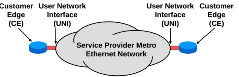
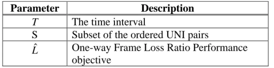
This document provides the model and framework for Ethernet Services. The model is built on the reference model as shown in Figure 1.
Service Provider Metro
Service Provider Metro
Ethernet Network
Ethernet Network
Customer
Customer
Edge
Edge
(CE)
(CE)
User Network
User Network
Interface
Interface
(UNI)
(UNI)
User Network
User Network
Interface
Interface
(UNI)
(UNI)
Customer
Customer
Edge
Edge
(CE)
(CE)
Figure 1 – Ethernet Services Model
The technical definition of a service is in terms of what is seen by each Customer Edge (CE). This includes the User Network Interface (UNI), which is the physical demarcation point between the responsibility of the Service Provider and the responsibility of the Subscriber. A UNI MUST be dedicated to a single Subscriber.1
The CE and MEN exchange Service Frames across the UNI. A Service Frame is an Ethernet [2] frame transmitted across the UNI toward the Service Provider (called an ingress Service Frame) or an Ethernet [2] frame transmitted across the UNI toward the Subscriber (called an egress Service Frame). The Service Frame consists of the first bit of the Destination MAC Address through the last bit of the Frame Check Sequence. The protocol as seen by the CE operating at the UNI MUST be standard Ethernet [2] with the exception that may have a length greater than that specified in [2]. (See Section 6.10 and Section 7.4.) There are no assumptions about the details of the Metro Ethernet Network. It could consist of a single switch or an agglomeration of networks based on many different technologies. Management of the services is not addressed in this document. See MEF 7, EMS-NMS Information Model [12], for the management perspective of the Ethernet Phase 1 service attributes.
Connectivity between UNIs is specified by the Ethernet Virtual Connection (EVC). There are a number of types of EVC and a number of service attributes that an EVC can have. These are described in Section 6.
There are a number of different service attributes for a UNI. These are described in Section 7. Section 8 contains a framework for defining a service. Attributes used in this framework include Ethernet Virtual Connection type, traffic parameters, Service Frame delivery, and performance.
6. Ethernet Virtual Connection Service Attributes
A fundamental aspect of Ethernet Services is the Ethernet Virtual Connection (EVC). An EVC is an association of two or more UNIs. These UNIs are said to be “in the EVC.” A given UNI can support more than one EVC via the Service Multiplexing attribute as described in Section 7.4.
1
Multiplexing traffic from multiple Subscribers onto a single link can be a valuable function but is an internal MEN function and is not visible at the UNI.
An ingress Service Frame that is mapped to the EVC (see Section 7.6) can be delivered to one or more of the UNIs in the EVC other than the ingress UNI. It MUST NOT be delivered back to the ingress UNI.2 It MUST NOT be delivered to a UNI not in the EVC. An EVC is always bi-directional in the sense that ingress Service Frames can originate at any UNI in an EVC.
6.1 Ethernet Virtual Connection Type Service Attribute
There are three types of EVC. They are as described in Sections 6.1.1, 6.1.2.1, and 6.1.2.2. 6.1.1 Point-to-Point EVC
In a Point-to-Point EVC, exactly two UNIs MUST be associated with one another. An ingress Service Frame mapped (see Section 7.7) to the EVC at one UNI MUSTNOT result in an egress Service Frame at a UNI other than the other UNI in the EVC. The rules under which a Service Frame is delivered to the destination UNI are specific to the particular service definition. Figure 2 illustrates two Point-to-Point EVCs.
EVC1
EVC2
Figure 2 – Point-to-Point EVCs
6.1.2 Multipoint EVCs
In a Multipoint EVC, two3 or more UNIs MUST be associated with one another. An ingress Service Frame mapped to the EVC at one of the UNIs MUSTNOT result in an egress Service Frame at a UNI that is not in the EVC.
6.1.2.1 Multipoint-to-Multipoint EVC
In a Multipoint-to-Multipoint EVC, the rules under which a frame is delivered to a UNI in the EVC are specific to the particular service definition. Typically, a single broadcast or multicast ingress Service Frame (as determined from the destination MAC address) at a given UNI would be replicated in the Metro Ethernet Network and a single copy would be delivered to each of the other UNIs in the EVC. This kind of delivery would also typically apply to a Service Frame for which the MEN has not yet learned an association of the destination MAC address with an EVC, UNI pair. Figure 3 illustrates a Multipoint-to-Multipoint EVC.
2
There may be frames that are not Service Frames that should be delivered back to the ingress UNI. An example might be a loop-back frame. These kinds of frames are beyond the scope of this Technical Specification. 3
A Multipoint-to-Multipoint EVC with two UNIs is different from a Point-to-Point EVC because one or more additional UNIs can be added to the Multipoint-to-Multipoint EVC.
Figure 3 – Multipoint-to-Multipoint EVC
6.1.2.2 Rooted-Multipoint EVC
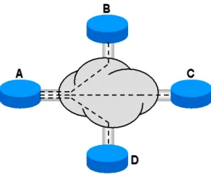
In a Rooted-Multipoint EVC, one or more of the UNIs MUST be designated as a Root and each of the other UNIs MUST be designated as a Leaf. An ingress Service Frame mapped to the EVC at a Root UNI MAY be delivered to one or more of the other UNIs in the EVC. An ingress Service Frame mapped to the EVC at a Leaf UNI MUST NOT result in an egress Service Frame at another Leaf UNI but MAY result in an egress Service Frame at some or all of the Root UNIs. The rules under which a frame is delivered to a UNI in the EVC are specific to the particular service definition. Typically, a single broadcast or multicast ingress Service Frame (as determined from the destination MAC address) at a Root UNI would be replicated in the Metro Ethernet Network and a single copy would be delivered to each of the other UNIs in the EVC. This kind of delivery would also typically apply to a Service Frame for which the MEN has not yet learned an association of the destination MAC address with an EVC, UNI pair. Figure 4 illustrates a Rooted-Multipoint EVC with one Root UNI.
Root
Leaf
Leaf
Broadcast, multicast and
Broadcast, multicast and unicastunicastunknownunknown Known
Known unicastunicast
Broadcast, multicast and Broadcast, multicast and unicastunicast
Figure 4 – Rooted-Multipoint EVC
6.2 EVC ID Service Attribute
The EVC ID is an arbitrary string administered by the Service Provider that is used to identify an EVC within the MEN. The EVC ID MUST be unique across all EVCs in the MEN. It is intended for management and control purposes. The EVC ID is not carried in any field in the Service Frame. As an example, the Acme Service Provider might use “EVC-0001898-ACME-MEGAMART” to represent the 1898th EVC in the MEN and the customer for the EVC is MegaMart.
6.3 UNI List Service Attribute
The UNI List for an EVC is a list of pairs of the form <UNI Identifier (see Section 7.1), UNI Type>. The list MUST have exactly one such pair for each UNI in the EVC. The UNI Type
MUST have the value either “Root” or “Leaf.” If the type of EVC is Point-to-Point or Multipoint-to-Multipoint, then the UNI Type MUST equal “Root.”
6.4 Maximum Number of UNIs Service Attribute
The Maximum Number of UNIs (MNU) service attribute specifies the maximum number of UNIs allowed in the UNI List service attribute. For a Point-to-Point EVC, MNU MUST be two. For a Multipoint EVC, MNU MUST be two or greater.
6.5 Service Frame Delivery Service Attributes 6.5.1 Types of Service Frame
There are several types of Service Frame. 6.5.1.1 Unicast Service Frame
This is a Service Frame that has a unicast destination MAC address. 6.5.1.2 Multicast Service Frame
This is a Service Frame that has a multicast destination MAC address. 6.5.1.3 Broadcast Service Frame
This is a Service Frame with the broadcast destination MAC address. 6.5.1.4 Layer 2 Control Protocol Service Frame
Given that there are several Layer 2 protocols used for various control purposes, it is important that Metro Ethernet Networks be able to process such information effectively.4 A Service Frame whose destination MAC address is one of the addresses listed in Table 1, MUST be treated as Layer 2 Control Protocol Service Frame.
Some Layer 2 Control protocols share the same destination MAC address and are identified by additional fields such as the Ethertype and a protocol identifier. Therefore, disposition of Service Frames carrying Layer 2 Control Protocols MAY be different for different protocols that use the
4
This capability will be especially important for Subscribers who choose to deploy IEEE 802.1D [8] or IEEE 802.1Q [9] bridges (as opposed to routers) as CEs.
same destination MAC address. [5] contains some recommendations for the delivery of specific Layer 2 Control protocols.
MAC Addresses5 Description
01-80-C2-00-00-00 through 01-80-C2-00-00-0F Bridge Block of protocols 01-80-C2-00-00-20 through 01-80-C2-00-00-2F GARP Block of protocols
01-80-C2-00-00-10 All Bridges Protocol
Table 1 – List of Standardized Layer 2 Control Protocols
A Service Provider MAY define additional addresses for identifying Layer 2 Control protocols in addition to those in Table 1.
6.5.1.5 Data Service Frame
A Service Frame that is either Unicast, Multicast, or Broadcast is referred to as a Data Service Frame. Thus, Service Frames are divided into two groups, Data Service Frames and Layer 2 Control Protocol Frames.
6.5.2 Service Frame Disposition
The disposition of an ingress Service Frame is described by one of the following:
• Discard: The Service Frame is discarded. An example is a Service Frame containing a particular Layer 2 Control protocol, (e.g., IEEE 802.3x), that is always discarded at the UNI. (See Section 7.13.) All ingress Service Frames with an invalid FCS MUST be discarded by the MEN.
• Deliver Unconditionally: No matter what the content (assuming correct FCS) of the Service Frame, it is delivered across the other (egress) UNI(s). This might be the behavior of a Point-to-Point EVC.
• Deliver Conditionally: The Service Frame is delivered across an egress UNI if certain conditions are met. An example of such a condition is that the destination MAC address is known by the Metro Ethernet Network to be “at” the destination UNI. Another example is broadcast throttling where some Service Frames with the broadcast destination MAC address are dropped to limit the amount of such traffic. When this option is in force the conditions MUST be specified.
• Tunnel: This applies only to Layer 2 Control Protocol Service Frames. See Section 6.7. More details about the disposition of Layer 2 Control Protocol Service Frames are presented in Sections 6.7 and 7.13.
5
Note that this is a description of the ideal service. Service Frames that should be delivered might be discarded due to network failure or congestion conditions. See the EVC Related Performance Service Attributes in Section 6.8.
6.5.3 Service Frame Transparency
All fields of each egress Service Frame MUST be identical to the same fields of the corresponding ingress Service Frame except as follows:
• The egress Service Frame MAY have an IEEE 802.1Q Customer VLAN Tag [10] while the corresponding ingress Service Frame does not. In this case the egress Service Frame
MUST have a recalculated FCS.
• The egress Service Frame MAY not have an IEEE 802.1Q Customer VLAN Tag [10] while the corresponding ingress Service Frame does have a Tag. In this case the egress Service Frame MUST have a recalculated FCS.
• If both the egress Service frame and corresponding ingress Service Frame have an IEEE 802.1Q Customer VLAN Tag [10], the contents of the Tag in the egress Service Frame
MAY be different from the contents of the Tag in the corresponding ingress Service Frame. If the contents of the ingress and egress tags are different, the egress Service Frame MUST have a recalculated FCS.
However, specific attributes of an EVC MAY enforce the condition that additional fields must be identical at ingress and egress. See Section 6.6.
6.6 CE-VLAN Tag Preservation Service Attributes
Service Frames at the UNI may contain an IEEE 802.1Q Customer VLAN Tag [10]. Such a Tag is referred to as a Customer Edge VLAN Tag (CE-VLAN Tag). The portion of the CE-VLAN Tag that identifies a VLAN indicates the Customer Edge VLAN ID (CE-VLAN ID). (See Section 7.6.) The portion of the CE-VLAN Tag that contains the Priority Code Point bits is called the Customer Edge VLAN CoS (CE-VLAN CoS). An EVC MAY have two attributes related to CE-VLAN Tag Preservation as described in the following two subsections.
6.6.1 CE-VLAN ID Preservation Service Attribute
A Service Frame is defined to have its CE-VLAN ID Preserved when the relationship between the ingress Service Frame and its corresponding egress Service Frame(s) is as described in Table 2.
Ingress Service Frame Egress Service Frame(s)6
No IEEE 802.1Q Customer VLAN Tag [10]
No IEEE 802.1Q Customer VLAN Tag [10] Contains IEEE 802.1Q
Customer VLAN Tag [10]
Contains IEEE 802.1Q Customer VLAN Tag [10] with VLAN ID equal to the VLAN ID of the Tag on the ingress Service Frame
Table 2 – CE-VLAN ID Preservation for a Service Frame
An EVC with the CE-VLAN ID Preservation Service Attribute MUST preserve the CE-VLAN ID for Service Frames as described in Table 3.
CE-VLAN ID/EVC Map Characteristic
Service Frames with CE-VLAN ID Preserved
All to One Bundling at all UNIs All Data Service Frames
All other cases All tagged Data Service Frames with VLAN ID in the
range 1 – 4094
Table 3 – CE-VLAN ID Preservation Service Attribute for an EVC
When an EVC includes a UNI at which more than one CE-VLAN ID is mapped to the EVC by the CE-VLAN ID/EVC Map (see Sections 7.9 and 7.10), the EVC MUST have the CE-VLAN ID Preservation Service Attribute.
Note that when the CE-VLAN ID configured for untagged and priority tagged Service Frames (see Section 7.6.1) is mapped to an EVC with the CE-VLAN ID Preservation Service Attribute, ingress untagged and priority tagged Service Frames at this UNI are not mandated to have their CE-VLAN ID preserved except in the case of All to One Bundling.
An obvious benefit of the CE-VLAN ID Preservation feature is enhanced operational simplicity. For example, for a Subscriber connecting multiple campuses using IEEE 802.1Q bridges, the feature obviates the task of renumbering VLANs in different corporate campuses.
6.6.2 CE-VLAN CoS Preservation Service Attribute
In an EVC with CE-VLAN CoS Preservation, an egress Service Frame resulting from an ingress Service Frame that contains a CE-VLAN CoS MUST have the identical CE-VLAN CoS.
6.7 EVC Layer 2 Control Protocol Processing Service Attribute
In some cases, it is desirable to carry Layer 2 Control Protocols across the Service Provider network. This is called Layer 2 Control Protocol tunneling because the frame MUST be passed through the Service Provider network without being processed7 and delivered to the proper UNI
6
Note that in the case of a Multipoint EVC, a single ingress Service Frame can result in more than one egress Service Frame.
7
For example, the Subscriber’s Ethernet information can be encapsulated in another frame separate from the control protocol frame.
or UNIs. The tunneling capability can be extremely useful, for example, when the Subscriber chooses to attach bridges to all UNIs and thus BPDUs need to be carried across the Network. When a Layer 2 Control Protocol is tunneled, the Service Frame at each egress UNI MUST be identical to the corresponding ingress Service Frame.
For a given EVC at a given UNI, the Service Provider defines which Layer 2 Control Protocols will be tunneled via the EVC and which will be discarded. If a Service Frame carrying a Layer 2 Control Protocol is tunneled, it MUST be tunneled on the EVC that is identified by the CE-VLAN/EVC Map for the CE-VLAN ID indicated by the Service Frame carrying the Layer 2 Control Protocol.8 See Section 7.7.
Note that if a Layer 2 Control Protocol is to be tunneled, then all UNIs in the EVC MUST be configured to pass the Layer 2 Control Protocol to the EVC. See Section 7.13.3.
6.8 Class of Service Identifier Service Attribute
Service Frame delivery performance is specified for all Service Frames transported within an EVC with a particular Class of Service instance. The Class of Service instance for a given Service Frame is identified by a Class of Service Identifier that is indicated by content in one or more fields in the Service Frame. For example, suppose that three Classes of Service are offered called silver, gold, and platinum and, at a given UNI, there are three instances of silver service, two instances of gold service and one instance of platinum service. Then there would be six Class of Service Identifiers, one for each Class of Service instance.
A Service Frame delivery performance MAY be to discard the Service Frame. Thus a Class of Service Identifier may be specified for Service Frame discard.
Service Frames mapped to different EVCs MUST have different Class of Service Identifiers. There SHALL be three mutually exclusive ways to determine the Class of Service Identifier from the content of a given Service Frame as described in Sections 6.8.1, 6.8.2, and 6.8.3.
6.8.1 Class of Service Identifier Based on EVC
In this case, all ingress Data Service Frames mapped to the EVC SHALL have the same Class of Service Identifier.
As an example, consider EVC 1 and EVC 2 at a UNI. Data Service Frames on EVC 1 have a first Class of Service Identifier that indicates gold service. Data Service Frames on EVC 2 have a second Class of Service Identifier that indicates silver service. All tunneled Layer 2 Control Protocols on EVC 1 also have the first Class of Service Identifier thus indicating gold service. All tunneled Layer 2 Control Protocols on EVC 2 have a third Class of Service Identifier that indicates platinum service.
8
Tunneling of BPDUs when Service Multiplexing is in effect at a UNI can lead to undesirable behavior. For example, if bridges are attached to all UNIs, then tunneled BPDUs will not reach all of the bridges and the Spanning Tree Protocol will not operate properly.
6.8.2 Class of Service Identifier Based on Priority Code Point Field
In this case, the Class of Service Identifier for an ingress Data Service Frame SHALL be determined by the EVC and non-overlapping sets of values of the CE-VLAN CoS. If the ingress Data Service Frame is untagged, it SHALL have the same Class of Service Identifier as an ingress Data Service Frame with Priority Code Point field = 0. The union of the sets of CE-VLAN CoS values MUST contain all of the possible CE-VLAN CoS values.
As an example, consider EVC 1 and EVC 2 at a UNI. Tagged and priority tagged Data Service Frames on EVC 1 with Priority Code Point values 4, 5, 6, and 7 have a first Class of Service Identifier that indicates gold service. Tagged and priority tagged Data Service Frames on EVC 1 with Priority Code Point values 0 and 3 have a second Class of Service Identifier that indicates silver service. Tagged and priority tagged Data Service Frames on EVC 1 with Priority Code Point values 1 and 2 have a third Class of Service Identifier that indicates Service Frame discard. Untagged Data Service Frames on EVC 1 also have the second Class of Service Identifier that indicates silver service. Tagged Data Service Frames on EVC 2 with Priority Code Point value 7 have a third Class of Service Identifier that indicates platinum service. All other Data Service Frames on EVC 2 have a fourth Class of Service Identifier that indicates gold service.
6.8.3 Class of Service Identifier Based on DSCP
In this case, the Class of Service Identifier for an ingress Data Service Frame containing an IP packet SHALL be determined by the EVC and non-overlapping sets of values of the DSCP.9 The union of the sets of DSCP values MUST contain all of the possible DSCP values. All ingress Data Service Frames not containing an IP packet and mapped to a given EVC SHALL
have the same Class of Service Identifier with a value agreed upon by the Subscriber and the Service Provider.
6.8.4 Class of Service Identifier Based on Layer 2 Control Protocol
In each method for determining the Class of Service Identifier described in Sections 6.8.1, 6.8.2, and 6.8.3, in addition Layer 2 Control Protocols that are tunneled on the EVC MAY be divided up into subsets and each subset MAY have a Class of Service Identifier.10
6.9 EVC Related Performance Service Attributes
The EVC Related Performance Service Attributes specify the Service Frame delivery performance. Four performance attributes are considered in this specification. These are Frame Delay Performance, Inter-Frame Delay Variation Performance, Frame Loss Ratio Performance, and Availability Performance.
9
In IP version 4, the DSCP is contained in the TOS field. In IP version 6, the DSCP is contained in the Traffic Class Octet.
10
For example, Service Frames carrying a BPDU could be assigned one Class of Service Identifier while Service Frames carrying a GARP protocol message could be assigned a different Class of Service Identifier.
Performance Attributes apply to “Qualified” Service Frames, which are frames that meet the following criteria for a given ordered pair of UNIs and a given Class of Service:
• Each Service Frame MUST be the first egress Service Frame at the same UNI j resulting from an ingress Service Frame at the other UNI i of the ordered pair. The Service Frame MAY be a Unicast (see Section 6.5.1.1), Multicast (see Section 6.5.1.2), Broadcast (see Section 6.5.1.3), or Layer 2 Control Protocol (see Section 6.5.1.4) Service Frame. Note that a single ingress Service Frame can result in multiple egress Service Frames, e.g., a Multicast Service Frame.
• The first bit of each Service Frame MUST arrive at the ingress UNI within the time interval T,
• Each Service Frame MUST have the Class of Service Identifier for the Class of Service instance in question, and
• Each ingress Service Frame MUST have an Ingress Bandwidth Profile compliance of Green.
Such Service Frames are elements of the set of Qualified Service Frames for an Ordered Pair of UNIs and a given Class of Service on an EVC.
Performance Attributes MUST NOT apply to Service Frames with the level of conformance determined to be Yellow or Red. Typically, the Frame Loss Ratio Performance will be degraded for Service Frames determined to be Yellow. Service Frames determined to be Red will be discarded. (See Section 7.11.2.5.)
For a given EVC and Class of Service instance, Performance Objectives MAY be specified over any given subset of the Ordered Pairs of UNIs (describing transmission direction) on the EVC. Once a subset of UNI pairs is defined, then all attributes in this section SHALL have performance objectives applying to that subset. Section 10.4 provides examples on how to structure these metrics to be UNI-oriented and EVC-oriented.
Values of the Service Frame delay, delay variation, and loss performance during periods of unavailable time MUST NOT be used to determine Service Frame delivery compliance. A process MUST be established to exclude all performance during unavailable periods from comparison with Service Frame performance objectives.
The assessment of all performance attributes SHOULD account for unexpected arrival phenomena, such as frame duplication, or frames arriving in a different order from that observed on ingress, and the presence of these phenomena alone do not necessarily exclude a Service Frame from the set of Qualified Service Frames.
6.9.1 Frame Delay Performance for a Point-to-Point EVC
NOTE – The contents of this section in [13] have been deleted, and the scope of Section 6.9.2 has been broadened to cover the Point-to-Point EVC case.
6.9.2 One-way Frame Delay Performance for an EVC
This section defines three performance attributes: the One-way Frame Delay Performance corresponding to a percentile of the distribution, the way Mean Frame Delay, and the One-way Frame Delay Range.
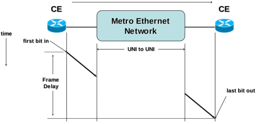
The One-way Frame Delay for an egress Service Frame at a given UNI in the EVC is defined as the time elapsed from the reception at the ingress UNI of the first bit of the corresponding ingress Service Frame until the transmission of the last bit of the Service Frame at the given UNI. This delay definition is illustrated in Figure 5.
Metro Ethernet
Metro Ethernet
Network
Network
UNI to UNI
UNI to UNI
first bit in
first bit in
last bit out
last bit out
time
time
CE
CE CECE
Frame
Frame
Delay
Delay
Figure 5 - Frame Delay for Service Frame
Note that this definition of Frame Delay for a Service Frame is the one-way11 delay that includes the delays encountered as a result of transmission across the ingress and egress UNIs as well as that introduced by the MEN.
There MAY be multiple Frame Delay Performance Objectives defined for a particular Class of Service instance on an EVC. Each such metric is based on a subset of the ordered pairs of UNIs in the EVC for a time interval T. Each Frame Delay Performance metric SHALL be defined as follows:
• Let the UNIs in the EVC be numbered from 1 to m. And let S be a subset of the ordered UNI pairs in the EVC. That is S ⊆
{
i, j |i=1,...,m, j =1,...,m,i≠ j}
.• Let dTi j
,
represent the P-Percentile of one-way delay for all Qualified Service Frames delivered to UNI j resulting from an ingress Service Frame at UNI i. If there are no such egress Service Frames at UNI j resulting from ingress Service Frames at UNI i, then
=
j i T
d , Undefined.
11
One-way delay is difficult to measure and therefore one way delay may be approximated from two way measurements. However these techniques are beyond the scope of this document.
• Then the One-way Frame Delay Performance metric SHALL be defined as the maximum value of all of the values dTi,j for i,j ∈S, unless all dTi,j are Undefined in which case the performance is Undefined.
• Let dTyxi,j =dTyi,j −dTxi,j represent the difference between Percentiles Py and Px (where Py > Px and i and j are the same pair in each term) of one-way delay for all Qualified
Service Frames delivered to UNI j resulting from an ingress Service Frame at UNI i. If there are no such egress Service Frames at UNI j resulting from ingress Service Frames at UNI i, then dTxyi,j = Undefined.
• Then the One-way Frame Delay Range Performance metric SHALL be defined as the maximum value of all of the values of the difference dTyxi,j =dTyi,j −dTxi,j for i,j ∈S, unless all dTxyi,j are Undefined in which case the performance is Undefined.
• Let µTi,j represent the arithmetic mean of one-way delay for all Qualified Service Frames delivered to UNI j resulting from an ingress Service Frame at UNI i. If there are no such egress Service Frames at UNI j resulting from ingress Service Frames at UNI i, then Tij =
,
µ Undefined.
• Then the One-way Mean Frame Delay Performance metric SHALL be defined as the maximum value of all of the values µTi,j for i,j ∈S, unless all µTi,j are Undefined in which case the performance is Undefined.
To restate the Frame Delay definition mathematically, let the UNIs in the EVC be numbered from 1 to m and let DTi j
,
be the set of one-way Frame Delay values for all Qualified Service Frames at UNI j resulting from an ingress Service Frame at UNI i. DTi,j can be expressed as
{
ij}
N j i j i j i
T d d d ij
D , 1, 2, ,
,
,..., ,
= , where dki,j is the one-way Frame Delay of the kth Service Frame. Define dTi,j for P > 0 as
(
)
≥ ≤ =∑
= otherwise 1 if , 100 | min , 1 , , , , Undefined N d d I N P dd i j
N k j i k j i j i T j i where,
(
)
≥ = otherwise 0 if 1, k k
d d d
d
j i T
d , is the minimal delay during the time internal T that P percent of the frames do not exceed. Note that when P>0, only values of d within DTi,j will satisfy P≤(100/N<i,k>)ΣI(d,dk).
Then a one-way Frame Delay Performance metric for an EVC can be expressed as
{
}
∈ = > ∈ = S j i N Undefined N S j i d d j i j i j i T S T , | 0 all when 0 where and , | max , , , , .The One-way Frame Delay attribute permits specification of multiple values for P, (P0, P1, P2, …) and corresponding objectives (dˆ0i,j ,
j i
dˆ1 , ,
j i
dˆ2 , , …). Another parameter is the objective
for the difference between the delay performance of two selected percentiles, Px and Py ,
expressed as = > − = 0 if 0 if ) ( , , , , , j i j i j i Tx j i Ty j i Tyx N Undefined N d d d
Then a one-way Frame Delay Range Performance metric for an EVC can be expressed as
{
}
, | 0 all when 0 where and , | max , , , ∈ = > ∈ = S j i N Undefined N S j i d d j i j i j i Tyx TyxS .The minimum one-way delay is an element of DTi,j , where dmini,j ≤dki,j (for all j
i
N
k=1,2,..., , ), and is a possible selection as one of the percentiles. The minimum delay represents the N<i,j>-1th percentile and all lower values of P as P→0.
Another One-way Frame Delay attribute is the arithmetic mean of DTi,j , which can be expressed as
( )
= > =∑
= 0 if 0 if 1 , , 1 , , , , j i j i N k j i k j i j i T N Undefined N d N j i µThen a One-way Mean Frame Delay Performance metric for an EVC can be expressed as
{
}
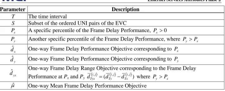
∈ = > ∈ = S j i N Undefined N S j i j i j i j i T j i T TS , | 0 all when 0 where and , | max , , , , µ µ µ .Parameter Description
T The time interval
S Subset of the ordered UNI pairs of the EVC x
P A specific percentile of the Frame Delay Performance, Px >0 y
P Another specific percentile of the Frame Delay Performance, where Py >Px
x
dˆ One-way Frame Delay Performance Objective corresponding to Px y
dˆ One-way Frame Delay Performance Objective corresponding to Py
yx
dˆ One-way Frame Delay Range Objective corresponding to the Frame Delay
Performance at Px and Py ( )
, ,
, ij
Tx j i Ty j
i
Tyx d d
d = − where Py >Px
µˆ One-way Mean Frame Delay Performance Objective
Table 4 – One-way Frame Delay Performance Parameters
Given T, S, Px, and a one-way Frame Delay Performance objective dˆ , expressed in time units, x the one-way Frame Delay Performance SHALL be defined as met over the time interval T for the subset S if and only if dT,S ≤dˆx. Further, given Py and a One-way Frame Delay Performance objective dˆ , expressed in time units, the objective for one-way Frame Delay Range between y Px and Py SHALL be defined as met over the time interval T for the subset S if and only if
yx TyxS d
d ≤ ˆ . Finally, given a One-way Mean Frame Delay Performance objective µˆ , expressed in time units, the Frame Delay Performance SHALL be defined as met over the time interval T if and only if µTS ≤µˆ.
Recall that if any of the above Service Frame Performance attributes are Undefined for time interval T and ordered pair i,j , then the performance for that ordered pair SHALL be excluded from calculations on the performance of pairs in S. For a given set S, if the Service Performance is Undefined for all ordered pairs, then the performance for SSHALL be defined as compliant.
For a Point-to-Point EVC, SMAY include one or both of the ordered pairs of UNIs in the EVC. For a Multipoint-to-Multipoint EVC, S MAY be any subset of the ordered pairs of UNIs in the EVC.
For a Rooted-Multipoint EVC, S MUST be such that all ordered pairs in S contain at least one UNI that is designated as a Root.
6.9.3 Inter-Frame Delay Variation Performance for a Point-to-Point EVC
NOTE – The contents of this section in [13] have been deleted, and the scope of Section 6.9.4 has been broadened to cover the Point-to-Point EVC case.
6.9.4 Inter-Frame Delay Variation Performance for an EVC
Inter-Frame Delay Variation (IFDV) is the difference between the one-way delays of a pair of selected Service Frames. This definition is borrowed from RFC3393 [6] where IP packet delay variation is defined. For a particular Class of Service Identifier and an ordered pair of UNIs in the EVC, IFDV Performance is applicable to Qualified Service Frames.
NOTE – Earlier documents refer to Inter-Frame Delay Variation as “Frame Delay Variation”. The Inter-Frame Delay Variation Performance SHALL be defined as the P-percentile of the absolute values of the difference between the Frame delays of all Qualified Service Frame pairs that satisfy the following conditions:
• The difference in the arrival times of the first bit of each Service Frame at the ingress UNI was exactly ∆t.
This definition is in agreement with the IP packet delay variation definition given in [6] where the delay variation is defined as the difference between the one-way delay of two packets selected according to some selection function and are within a given interval [T1, T2].
Inter-Frame Delay Variation Performance depends on the choice of the value for ∆t. Values for both ∆t and T typically should be chosen to achieve a reasonable level of statistical accuracy. The choice of the value for ∆t can be related to the application timing information. As an example for voice applications where voice frames are generated at regular intervals, ∆t may be chosen to be few multiples of the inter-frame time.
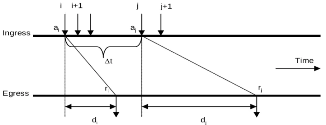
Let ai be the time of the arrival of the first bit of the ith Service Frame at the ingress UNI, then the two frames i and j are selected according to the selection criterion:
{
aj −ai =∆t and j>i}
Let ri be the time frame i is successfully received (last bit of the frame) at the egress UNI, then the difference in the delays encountered by frame i and frame j is given by di−dj. Define
(
i i)
(
j j) (
j i) (
j i)
ji
ij d d r a r a a a r r
d = − = − − − = − − −
∆
With djbeing the delay of the jth frame, a positive value for di−dj implies that the two frames are closer together at the egress UNI while a negative value implies that the two frames are further apart at the egress UNI. If either or both frames are lost or not delivered due to, for example, FCS violation, then the value ∆dij is not defined and does not contribute to the evaluation of the Inter-Frame Delay Variation.
Figure 6 shows a depiction of the different times that are related to Inter-Frame Delay Variation Performance.
Ingress
Egress
i i+1 j j+1
ai aj
∆t
ri rj
Time
di dj
Figure 6 – Inter-Frame Delay Variation Definition
For a particular Class of Service instance, Inter-Frame Delay Variation Performance metrics
MAY be specified over any given subset of two or more UNIs on an EVC. Each such metric is based on a subset of the ordered pairs of UNIs in the EVC for a time interval T. Each Inter-Frame Delay Variation Performance metric SHALL be defined as follows:
• Let the UNIs in the EVC be numbered from 1 to m. And let S be a subset of the ordered UNI pairs in the EVC. That is S⊆
{
i, j |i=1,...,m, j=1,...,m,i≠ j}
.• Let ∆d~Ti,j be the P-percentile of the absolute value of the difference between the Frame Delays of all Qualified Service Frame pairs whose difference in the arrival times of the first bit of each Service Frame in the pair at UNI i was exactly ∆t.
• If there are no such pairs of Service Frames for UNI i and UNI j, then
Undefined dTij =
∆~ ,
.
• Then the Inter-Frame Delay Variation Performance metric SHALL be the maximum of the values ∆d~Ti,j for i,j ∈S, unless all ∆d~Ti,j are Undefined in which case the performance is Undefined.
To restate the definition mathematically, let the UNIs in the EVC be numbered from 1 to m. And let S be a subset of the ordered UNI pairs in the EVC. That is
{
i j i m j m i j}
S⊆ , | =1,..., , =1,..., , ≠ . Let
} ,...,
,
{ 1, 2, ,
,
,
j i N j
i j i j
i
T d d d ij
be the set of all absolute value of delay variations for all eligible pairs of Qualified Service Frames from UNI i to UNI j where the difference in the arrival times of the first bit of each Service Frame at the ingress UNI was exactly ∆t. Define
≥ ∆ ≤ = ∆
∑
= otherwise 1 if ) , ( 100 | min ~ , 1 , , , , Undefined N d d I N P dd ij
N k j i k j i j i T j i where;
(
)
otherwise if 0 1, d d d
d
I ≥∆
=
∆ .
Then an Inter-Frame Delay Variation Performance metric for an EVC can be expressed as
{
}
∈ = ≥ ∈ ∆ = ∆ S j i N Undefined N S j i d d j i j i j i T S T , | 0 all when 1 where and , | ~ max ~ , , , , .For the SLS, an Inter-Frame Delay Variation metric MUST specify a set of parameters and an objective. The parameters and objective for an Inter-Frame Delay Variation Performance metric are given in Table 5.
Parameter Description
T The interval
S Subset of the ordered UNI pairs of the EVC
P Inter-Frame Delay Variation Performance percentile
∆t The separation between frame pairs for which Inter-Frame Delay
Variation Performance is defined
d Inter-Frame Delay Variation Performance Objective
Table 5 – Inter-Frame Delay Variation Parameters
Given T, S, P, ∆t, and d, the Inter-Frame Delay Variation Performance SHALL be defined as met over the time interval T for the subset S if and only if ∆d~T,S ≤d.
Recall that if the Inter-Frame Delay Variation is Undefined for time interval T and ordered pair
j
i, , then the performance for that ordered pair SHALL be excluded from calculations on the performance of pairs in S. For a given set S, if the Service Performance is Undefined for all
ordered pairs, then the performance for SSHALL be defined as compliant.
For a Point-to-Point EVC, S MAY be include one or both of the ordered pairs of UNIs in the EVC.
For a Multipoint-to-Multipoint EVC, S MAY be any subset of the ordered pairs of UNIs in the EVC.
For a Rooted-Multipoint EVC, S MUST be such that all ordered pairs in S contain at least one UNI that is designated as a Root.
6.9.5 One-way Frame Loss Ratio Performance for a Point-to-Point EVC
NOTE – Section 6.9.7 refers to this section for the definition of the frame loss ratio flr
( )
∆ti of a Point-to-Point EVC. For the purposes of the Availability Performance, the Frame Loss Ratio Performance (defined in detail in Section 6.9.6) SHALL be defined as follows:( )
{
}
∈ = ≥ ∈ = = ∆ ∆ ∆ ∆ ∆ S j i I I S j i FLR FLR tflr i j
t j i t j i t S t i i i i i , | 0 all when 0 1 where and , | max , , , ,
where the set of ordered pairs, S, contains both ordered pairs of UNIs in the Point-to-Point EVC. NOTE – The contents of this section in [13] have been deleted, and the scope of Section 6.9.6 has been broadened to cover the Point-to-Point EVC case.
6.9.6 One-way Frame Loss Ratio Performance for an EVC
There MAY be multiple One-way Frame Loss Ratio Performance metrics defined for a particular Class of Service instance on an EVC. Each such metric is based on a subset of the ordered pairs of UNIs in the EVC for a time interval T. Each One-way Frame Loss Ratio Performance metric SHALL be defined as follows:
• Let the UNIs in the EVC be numbered from 1 to m. And let S be a subset of the ordered UNI pairs in the EVC. That is S⊆
{
i, j |i=1,...,m, j=1,...,m,i≠ j}
.• Let ITi,j denote the number of ingress Service Frames at UNI i whose first bit arrived at UNI i during the time interval T, whose Ingress Bandwidth Profile compliance was Green, and that should have been delivered to UNI j according to the Service Frame Delivery service attributes (see Sections 6.5.2, 6.7, and 7.13). Each Service Frame can be a Unicast (see Section 6.5.1.1), Multicast (see Section 6.5.1.2), Broadcast (see Section 6.5.1.3), or Layer 2 Control Protocol (see Section 6.5.1.4) Service Frame.
• Let ETi,j denote the number of such Service Frames delivered to UNI j.
• Define ≥ × − = otherwise 1 if 100 , , , , , Undefined I I E I FLR j i T j i T j i T j i T j i T .