COMBINING HARDWARE MANAGEMENT WITH MIXED-CRITICALITY PROVISIONING IN MULTICORE REAL-TIME SYSTEMS
Namhoon Kim
A dissertation submitted to the faculty of the University of North Carolina at Chapel Hill in partial fulfillment of the requirements for the degree of Doctor of Philosophy in the Department of Computer Science.
Chapel Hill 2019
ABSTRACT
Namhoon Kim: Combining Hardware Management with Mixed-Criticality Provisioning in Multicore Real-Time Systems
(Under the direction of James H. Anderson)
Safety-critical applications in cyber-physical domains such as avionics and automotive systems require strict timing constraints because loss of life or severe financial repercussions may occur if they fail to produce correct outputs at the right moment. We call such systems “real-time systems.” When designing a real-time system, a multicore platform would be desirable to use because such platforms have advantages in size, weight, and power constraints, especially in embedded systems. However, the multicore revolution is having limited impact in safety-critical application domains. A key reason is the “one-out-of-m” problem: when validating real-time constraints on anm-core platform, excessive analysis pessimism can effectively negate the processing capacity of the additionalm-1 cores so that only “one core’s worth” of capacity is available. The root of this problem is that shared hardware resources are not predictably managed. Two approaches have been investigated previously to address this problem: mixed-criticality analysis, which provision less-critical software components less pessimistically, and hardware-management techniques, which make the underlying platform itself more predictable.
The goal of the research presented in this dissertation is to combine both approaches to reduce the capacity loss caused by contention for shared hardware resources in multicore platforms. Towards that goal, fundamentally new criticality-cognizant hardware-management tradeoffs must be explored. Such tradeoffs are investigated in the context of a new variant of a mixed-criticality framework, calledMC2, that supports configurable criticality-based hardware management. This framework allows specific DRAM banks and areas of the last-level cache to be allocated to certain groups of tasks to provide criticality-aware isolation. MC2is further extended to support the sharing of memory locations, which is required to realize the ability to support real-world workloads.
ACKNOWLEDGEMENTS
This dissertation could not have been accomplished without the help and support of many people. First and foremost, I wish to thank my advisor, Jim Anderson, for his guidance and patience during my time at Chapel Hill. I would also like to thank my dissertation committee, Sanjoy Baruah, Don Smith, Donald Porter, Rodolfo Pellizzoni, and Frank Mueller, for their guidance on my research and this dissertation.
I also wish to thank all of my co-authors, Micaiah Chisholm, Nathan Otterness, Stephen Tang, Bryan Ward, Glenn Elliott, Jeremy Erickson, who all helped me on many different works, and often stayed up all night revising a paper before a submission deadline. I am especially thankful for Micaiah Chisholm. The results of this work were obtained as part of a collaborative effort with Micaiah. I would like to also thank my wonderful colleagues from the Real-Time Systems Group at UNC, Mac Mollison, Catherine Nemitz, Ming Yang, Sergey Voronov, Tanya Amert, Sims Osborne, Kecheng Yang, Zhishan Guo, Bipasa Chattopadhyay, Joshua Bakita, Clara Hobbs, and Peter Tong, who provided helpful conversations and comments on ideas and presentations.
I wish to acknowledge the help provided by the staff of the UNC Computer Science Department. I owe special thanks to Mike Stone, John Sopko, and Bil Hays for keeping our machines running, and Jodie Turnbull, Denise Kenney, and Melissa Wood for keeping me out of paperwork trouble. I would also like to extend my thanks to the friends I have made throughout my time at UNC, including Young-woon Cha, Cheng-Yang Fu, Amos Wang, Chun-Wei Liu, Ilwoo Ryu, Tahsin Kabir, Junpyo Hong, Eunbyung Park, and Seulki Lee. Finally, I would like to thank my parents for their love and support during the years I was in Chapel Hill.
TABLE OF CONTENTS
LIST OF TABLES. . . x
LIST OF FIGURES. . . xi
LIST OF ABBREVIATIONS . . . xiv
CHAPTER 1: Introduction . . . 1
1.1 Real-Time Systems . . . 2
1.2 Multicore Architectures . . . 2
1.3 Mixed Criticality . . . 3
1.4 Thesis Statement . . . 4
1.5 Contributions . . . 5
1.5.1 Enabling Hardware Management inMC2. . . 5
1.5.2 Support for Data Sharing Between Tasks . . . 6
1.5.3 Techniques to Allow Shared Libraries . . . 6
1.5.4 Techniques to Reduce OS-Induced Interference . . . 6
1.6 Organization . . . 7
CHAPTER 2: Background . . . 8
2.1 Real-Time Scheduling . . . 8
2.1.1 Task Model . . . 8
2.1.2 Scheduling Algorithms. . . 9
2.1.3 Schedulability. . . 10
2.1.4 Mixed-Criticality Scheduling . . . 13
2.2 MC2. . . 14
2.3 Multicore Platforms . . . 15
2.3.1 Processing Units . . . 15
2.3.3 An Example Hardware Platform . . . 16
2.4 Shared Hardware Resources . . . 17
2.4.1 Caches . . . 17
2.4.2 DRAM Banks. . . 20
2.4.3 Unmanaged Hardware Resources . . . 21
2.5 LITMUSRT. . . 21
2.6 Summary . . . 22
CHAPTER 3: Enabling Hardware Management inMC2 . . . 23
3.1 Hardware Management Techniques . . . 23
3.1.1 Cache Partitioning . . . 24
3.1.2 DRAM Bank Partitioning . . . 26
3.2 Resource Allocation Strategy . . . 28
3.2.1 LLC Allocation . . . 28
3.2.2 DRAM Allocation and Bank Interleaving . . . 30
3.3 Implementation . . . 30
3.3.1 General Information . . . 31
3.3.2 MC2Task Scheduler. . . 31
3.3.3 Allocating Colored Pages to Tasks . . . 32
3.3.4 Coarse-Grained OS Isolation . . . 34
3.4 Micro-Benchmark Experiments. . . 35
3.4.1 Impact of Providing Full Isolation at Levels A and B. . . 36
3.4.2 Space Tradeoffs . . . 43
3.4.3 Impact of Sharing at Level C: Additional Considerations . . . 45
3.4.4 Impact of Coarse-Grained OS Isolation . . . 46
3.4.5 Optimizing LLC Partitions . . . 49
3.5 Schedulability Study. . . 49
3.5.1 Overhead-Aware Schedulability Study. . . 49
CHAPTER 4: Introducing Sharing inMC2 . . . 60
4.1 User-Level Data Sharing . . . 61
4.1.1 IPCs . . . 61
4.1.2 Problem Caused by User-Level Data Sharing. . . 63
4.1.3 Techniques for Mitigating Interference Due to Shared Memory . . . 64
4.1.4 Implementation . . . 65
4.1.5 Micro-Benchmark Experiments . . . 66
4.1.6 Optimizations . . . 69
4.1.7 Schedulability Study. . . 72
4.2 Shared Libraries . . . 77
4.2.1 Libraries and Linking . . . 78
4.2.2 Techniques to Allow Shared Libraries . . . 81
4.2.3 Implementation . . . 84
4.2.4 Introducing Memory Constraints . . . 86
4.2.5 Evaluation . . . 89
4.3 Sharing Between Kernel and User Space. . . 94
4.3.1 OS-Induced Sharing . . . 95
4.3.2 Memory Interference from I/O Devices . . . 97
4.3.3 Implementation . . . 100
4.3.4 Optimizing Interference . . . 101
4.3.5 Micro-Benchmark Experiments . . . 103
4.3.6 Schedulability Study. . . 110
4.4 Summary . . . 115
CHAPTER 5: Conclusion. . . 116
5.1 Summary of Results . . . 116
5.2 Other Related Work . . . 119
5.3 Future Work . . . 121
5.3.1 Richer Data Sharing Models . . . 121
APPENDIX A: Schedulability Graphs for The Study Described in Chapter 3 . . . 125
APPENDIX B: Schedulability Graphs for The Study Described in Section 4.1 . . . 196
APPENDIX C: Schedulability Graphs for The Study Described in Section 4.2 . . . 291
APPENDIX D: Schedulability Graphs for The Study Described in Section 4.3 . . . 375
LIST OF TABLES
Table 3.1 Task-set parameters and distributions . . . 51
Table 3.2 Generated PET values . . . 52
Table 3.3 Assignment of execution time parameters to PETs. . . 52
Table 4.1 Benefits accrued under different schemes. Benefits are cache isolation (CI), bank isolation (BI), cache warm (CW) during every access, and no copy (NC) phase required . . . 73
Table 4.2 Task-set parameters and distributions . . . 74
Table 4.3 DRAM consumption of an example task system assuming non-shared and selectively shared libraries . . . 87
Table 4.4 ConsideredMC2variants . . . 90
Table 4.5 Task-set parameters and distributions. In Category 6, last column,I:P denotes that intervalI is selected with probabilityP . . . 91
Table 4.6 The size of the code segments of considered libraries under selective sharing. . . 92
Table 4.7 Micro-benchmark programs . . . 105
LIST OF FIGURES
Figure 2.1 Examples of two scheduling approaches on a quad-core platform . . . 10
Figure 2.2 Example of bounded tardiness for a task system under G-EDF on two processors . . . 13
Figure 2.3 Scheduling inMC2on a quad-core machine . . . 14
Figure 2.4 The architecture of quad-core ARM Cortex-A9 . . . 17
Figure 2.5 Set-based cache partitioning on the ARM Cortex-A9 . . . 18
Figure 2.6 Way-based cache partitioning on the ARM Cortex-A9 . . . 19
Figure 2.7 The architecture of a DRAM chip that has eight banks . . . 20
Figure 3.1 Physical address decoding of NXP i.MX6 processor . . . 25
Figure 3.2 Page layout in DRAM banks when bank interleaving is off . . . 27
Figure 3.3 Page layout in DRAM banks when bank interleaving is on . . . 27
Figure 3.4 LLC allocation variants . . . 29
Figure 3.5 DRAM allocation strategy . . . 30
Figure 3.6 The arrangement of the kernel code and data in memory . . . 31
Figure 3.7 A list of free blocks managed by the buddy allocator. . . 33
Figure 3.8 Modifiedm+1 lists of free blocks in the buddy allocator . . . 34
Figure 3.9 Migration of seven pages to a task assigned the first four LLC colors . . . 35
Figure 3.10 Execution-time data for the 256KB-WSS micro-benchmark program . . . 38
Figure 3.11 Execution-time data for the Matrix program . . . 39
Figure 3.12 Execution-time data for the 32KB-WSS micro-benchmark program . . . 41
Figure 3.13 Conflict in the L1 cache. . . 42
Figure 3.14 Two potential mappings of eight data pages with nine LLC colors. . . 42
Figure 3.15 Histograms showing the percentage improvement in the ACETs and WCETs of 256KB-WSS micro-benchmark program and the Matrix program provided by sharing the program’s allocated LLC area, inst-ead of ensuring isolation . . . 44
Figure 3.17 Execution times of a Level-B micro-benchmark program with and
without coarse-grained OS isolation . . . 47
Figure 3.18 Cross-core OS interference. . . 48
Figure 3.19 Utilizations generated under different LLC allocations for three example tasks . . . 53
Figure 3.20 Two methods for calculating ACETs in Step 3.6. . . 55
Figure 3.21 Comparison ofC7 i andCi8for a generated task . . . 56
Figure 3.22 Representative schedulability plots. . . 57
Figure 4.1 Measured WCET for the 256KB-WSS synthetic task considered in Chapter 3 assuming it is allocated eight LLC ways . . . 63
Figure 4.2 Examples of page mappings for CL . . . 67
Figure 4.3 Measured execution time data for accessing shared buffers . . . 68
Figure 4.4 Example task system with PCBs and WFBs with tasks at different criticality levels (denoted by superscripts) . . . 70
Figure 4.5 New LLC allocation that extends that in Figure 3.4 (a) by allowing several ways to be allocated for holding locked buffers. Several such buffers (bx,by,bz) are depicted . . . 72
Figure 4.6 Representative schedulability plots. . . 76
Figure 4.7 Memory usage comparison of static linking and dynamic linking . . . 79
Figure 4.8 Task memory map with(a)static vs.(b)dynamic linking . . . 80
Figure 4.9 Virtual address space and mappings to page frames and LLC underMC2. . . 82
Figure 4.10 Page allocation in DRAM banks . . . 88
Figure 4.11 Interleaved LLC allocation . . . 88
Figure 4.12 Representative schedulability plots. . . 93
Figure 4.13 Simplified direct disk I/O data flow . . . 98
Figure 4.14 Simplified USB camera I/O data flow . . . 99
Figure 4.15 Variant 4 (Way-based-isolated LLC) . . . 103
Figure 4.16 Measured WCETs for Sender and Receiver . . . 104
Figure 4.17 Micro-benchmark tasks and resource allocations . . . 106
Figure 4.19 Matrix execution times as a function of allocated LLC space . . . 108
Figure 4.20 Synthetic WCETs under two allocation scenarios. . . 109
Figure 4.21 Representative schedulability plots. . . 114
Figure 5.1 NXP i.MX8 . . . 122
Figure 5.2 Intel E5-2658A v3 . . . 123
LIST OF ABBREVIATIONS
ACET Average-Case Execution Time API Application Program Interface BI Bank Isolation
C-EDF Clustered Earliest Deadline First CAT Cache Allocation Technology CE Concurrency Elimination CI Cache Isolation
CL Last-Level Cache Locking CPU Central Processing Unit CVA Compliant Vector Analysis
CW Cache Warm
DAG Directed Acyclic Graph DIS Data Intensive Systems DMA Direct-Memory Access
DRAM Dynamic Random-Access Memory EDF Earliest Deadline First
FIFO First In, First Out
G-EDF Global Earliest Deadline First GFP Get Free Page
HRT Hard Real-Time I/O Input/Output
ICAS Ideal Cache Allocation Size IPC Interprocess Communication JLFP Job-Level Fixed-Priority
L1 Level 1
L1-I Level 1 Instruction
L2 Level 2
L3 Level 3
L4 Level 4
LLC Last-Level Cache LP Linear Programming MMU Memory Management Unit
NC No Copy
OS Operating System
P-EDF Partitioned Earliest Deadline First P-RES Partitioned Uniprocessor Reservation PCB Producer/Consumer Buffer
PET Provisioned Execution Time PFN Page Frame Number
RM Rate-Monotonic RSS Resident Set Size
RTOS Real-Time Operating System SBP Selective LLC Bypass SPM Scratchpad Memory SRT Soft Real-Time SSD Solid State Disk
SWaP Size, Weight, and Power TLB Translation Lookaside Buffer USB Universal Serial Bus
WCET Worst-Case Execution Time WFB Wait-Free Buffer
CHAPTER 1: INTRODUCTION
Applications in safety-critical domains, such as in the avionics and automotive industries, require not only logical correctness but also temporal correctness. These applications must produce correct outputs within precise time constraints. Such applications are calledreal-time applications.
To guarantee the temporal correctness of real-time applications, the system designer must be able to predict application behavior. An analytical model allows the designer to do this, and these models are used to design and build real-time systems. However, sincemulticorearchitectures have emerged as the dominant platform for embedded systems, this type of analysis requires very pessimistic assumptions on provisioning worst-case behaviors due to the nature of multicore platforms. Such analysis pessimism results in severe capacity loss in designing real-time systems on such platforms. A multicore processor is a single computing component with two or more cores for enhanced performance, reduced power consumption, and more efficient simultaneous processing of multiple tasks. These multicore platforms have the potential to enable a wealth of new computationally intensive features in safety-critical domains, such as the avionics and automotive industries. Safety-critical systems requirecertificationbecause these systems may cause significant damage or loss of life if they are not operating properly. Government and international agencies have published standards, reports, and position papers to provide guidelines in designing safety-critical real-time applications. However, certifying the real-real-time correctness of a system running onmcores may require pessimistic analysis to guarantee correct behavior that entails over-provisioning the required computational capacity. Such pessimism may be so extreme, that the processingcapacityof the additionalm-1 cores is entirely negated. In effect, only “one core’s worth” of capacity can be utilized even thoughmcores are available. In safety-critical application domains, such as avionics, this “one-out-of-m” problem has led to the common practice of simply disabling all but one core. This problem is the most serious unresolved obstacle in research work on real-time multicore resource allocation today. Certification difficulties in multicore platforms are extensively discussed in a recent position paper by the U.S. Federal Aviation Administration, CAST-32A (Certification Authorities Software Team, 2016).
and memory banks, that are not predictably managed. Several programs may access these shared hardware resources at the same time, which causes contention for those resources. This contention for shared resources results in pessimisticworst-case execution time (WCET)assumptions due to cross-core interference and unpredictability in accessing such resources, and this pessimism entails the under-utilization of a system. In this dissertation, we address the one-out-of-mproblem by mitigating such pessimism in order to reduce capacity loss for multicore platforms.
We begin this chapter with a brief introduction to real-time systems and mixed-criticality analysis techniques, which are used in the approach we investigate. We then discuss multicore architectures and challenges caused by sharing hardware resources. Next, we present our thesis and describe the contributions we make via the results of this dissertation. Finally, we outline the organization of this dissertation.
1.1 Real-Time Systems
The meaning of the term “real time” varies widely depending on the application domain. To clarify our definition of “real time,” we assume that a real-time system describes a hardware and software system where computationaltasksthat comprise one or more real-time applications are subjected to timing constraints. A real-time system is said to be correct when all tasks in the system satisfy both logical and temporal correctness. In other words, all tasks in the system must produce correct output within a designated time interval. Each task releases recurring work, which is called ajob, according to a predictable rate or time interval. The completion time of each job must occur by a specifieddeadline, which occurs within some interval of time after the job’s release. In ahard real-time (HRT)system, all deadlines must be met. If a job misses a deadline, the system is considered to have failed. In asoft real-time (SRT)system, some deadline misses are acceptable, but the response time of a job should be bounded. A task system, a set of real-time tasks, is said to beschedulableif timing constraints are guaranteed to be satisfied under a given scheduling algorithm, which is responsible for allocating processor time to each job. In order to guarantee that all timing constraints will be met under a given scheduling algorithm,scheduliability analysismust be performed.
1.2 Multicore Architectures
embedded systems. In a multicore platform, two or more processors are integrated in a single physical circuit. The advent of multicore technologies aroused interest in the analysis and design of multiprocessor real-time scheduling algorithms. Scheduling algorithms in a multicore platform can be generally classified into three categories: partitioned, global, or clustered. Under partitioned scheduling, tasks are statically assigned to processors. Under global scheduling, tasks may migrate across processors. Clustered scheduling is a hybrid of partitioned and global scheduling: processors are partitioned into clusters, and each task is assigned to one cluster and can migrate among the processors of that cluster.
While multicore platforms provide many advantages, there are many challenges in designing real-time systems to run on a multicore platform. Since two or more processors exist in a multicore platform, those processors share many hardware resources, such as the last-level cache (LLC), memory bus, memory controller, and memory banks. Contention for this shared hardware can significantly affect the response time of real-time tasks on multicore platforms. For example, when a processor loads its instructions and data into the LLC, the subsequent accesses hit in the cache. However, the loaded instructions and data subsequently could be evicted by other processors because the LLC is shared among processors on multicore platforms. The unpredictability of these cache evictions can seriously affect the timing behavior of real-time tasks. Also, when all processors are executing memory-intensive applications, the applications could cause contention with respect to the memory controller, bus, and memory banks. This contention also affects the timing behavior of real-time tasks. Due to this unpredictable cross-core interference, pessimistic execution-time provisioning is often used in the analysis of such systems. This analysis pessimism results in capacity loss on multicore platforms.
1.3 Mixed Criticality
When designing a mixed-criticality real-time system, a common approach is to assign higher priorities to higher-criticality tasks. However, due to cross-core interference from lower-criticality tasks on other processors, this approach requires pessimistic WCET provisioning for higher-criticality tasks. This results in severe under-utilization on multicore platforms.
To mitigate such pessimism due to the unpredictable nature of shared resources on multicore platforms, two orthogonal approaches to improve system utilization have been investigated. One approach is to manage shared hardware. Resource partitioning is a promising approach for managing hardware predictably. For example, a dedicated partition in cache for a safety-critical task prevents its instructions and data from unexpected cache replacements caused by non-safety-critical tasks. Alternatively, support could be introduced for scheduling accesses to shared resources. For example, scheduling memory accesses may guarantee exclusive accesses and reduce pessimism by allowing deterministic accesses to shared resources. While hardware-management approaches seem promising, another promising solution is the application of mixed-criticality analysis assumptions. Vestal (2007) proposed amixed-criticality task modelin which multiple WCETs are specified for each task at different levels of assurance. Since higher-criticality tasks require greater levels of assurance, a WCET at a higher criticality level is typically greater than WCETs for the same task at lower criticality levels. As explained in Chapter 2, when checking timing constraints, these different WCETs are applied in a way that allows for increased platform utilization.
1.4 Thesis Statement
To mitigate analysis pessimism due to the unpredictable shared resources on multicore platforms, two orthogonal approaches to improve system utilization have been investigated, namely, hardware-management techniques and mixed-criticality analysis, as discussed above. These prior research efforts share a similar goal of improving platform utilization, but their orthogonal nature raises research questions pertaining to the combination of both approaches: 1) Can we achieve better platform utilization by introducing criticality-aware hardware management? 2) If so, how should resources be managed both within and across criticality levels? 3) If we can provide task isolation by managing hardware resources, can we support real-world workloads that must necessarily break isolation?
guarantees, more optimistically provisioned lower-criticality tasks might actuallybenefitfrom less restricted hardware sharing because shared hardware is often designed to improve average-case performance or throughput. In addition, in order to realize the ability to support real-world workloads, sharing between tasks must be supported. Data sharing directly breaks the isolation often provided for higher-criticality tasks. Shared librariesare another common source of sharing. Statically linked librariescan eliminate such sharing, but this solution comes with a cost because all needed libraries are replicated on a per-task basis. Furthermore, user tasks are not the only source of hardware interference. The operating system (OS) contends for hardware resources as well. The OS executes concurrently with user-level tasks when it handles interrupts or runs system services.
Motivated by these observations, we present the following thesis statement:
“The capacity loss of real-time systems on multicore mixed-criticality systems can be
miti-gated by combining mixed-criticality analysis and hardware-management techniques,
partic-ularly by managing the shared LLC and dynamic random-access memory (DRAM) memory.
Such a combination approach can be designed to mitigate hardware contention caused by data
sharing between tasks, shared libraries, and sharing between the kernel and user space in order
to support practical real-time workloads.”
To support this thesis, we have designed and implemented hardware-management techniques in a framework calledMC2(mixed-criticality on multicore)(Herman et al., 2012; Mollison et al., 2010; Ward et al., 2013), which has been the subject of continuing research by the Real-Time Systems Group at the University of North Carolina at Chapel Hill. We have added support for data sharing between tasks, shared libraries, and sharing between the kernel and user space. We also have evaluated the proposed framework with overhead-aware schedulability studies.
1.5 Contributions
We now present an overview of our contributions in this dissertation that support the thesis above.
1.5.1 Enabling Hardware Management inMC2
Our main contribution in this dissertation is the design and implementation of a hardware management
new framework that enables shared hardware management inMC2. The newMC2 framework reduces capacity loss by providing criticality-aware task isolation. The newMC2framework is highly configurable and supports fine-grained resource management. We consider various configurations and evaluate each one with respect to real-time schedulability with measured platform overheads considered, using workload assumptions based on trends observed in benchmark programs.
1.5.2 Support for Data Sharing Between Tasks
In Section 4.1, we extend ourMC2framework to support data sharing among tasks. When hardware management is combined with mixed-criticality analysis assumptions, the pessimism in provisioning WCETs can be greatly reduced. However, the ability to support real-world workloads has not been realized. A key barrier is a lack of support for data sharing among tasks. Data sharing among tasks could break the task isolation provided by hardware management inMC2. We devised and implemented techniques to manage shared buffers that can be used to transfer data between tasks (Chisholm et al., 2016). We show that our buffer-allocation techniques eliminate or reduce the deterioration caused by the introduction of sharing.
1.5.3 Techniques to Allow Shared Libraries
A shared library is a module that is intended to be shared by applications. Libraries used by an application are loaded into memory at run time. However, this read-only sharing breaks isolation properties because the code is loaded by the first program that uses the library, which means that the code can be loaded into any LLC partition. To eliminate such unpredictable code pages, statically linked libraries can be used where all needed libraries are replicated on a per-program basis. This resolves the issue of breaking isolation, but statically linked libraries require more memory space.
In Section 4.2, we consider main memory as a constrained resource. When memory is considered as a constrained resource, the wasteful practice of fully replicating shared libraries can degrade system utilization significantly. To remedy this situation, we propose an approach that ensures hardware isolation without degrading system utilization (Kim et al., 2017a).
1.5.4 Techniques to Reduce OS-Induced Interference
secondary storage devices, an interaction between the OS and a user program is required to complete each I/O operation. In addition, the OS frequently executes interrupt service routines or system services. These activities may interfere with a real-time task by consuming CPU cycles or by accessing shared hardware resources.
In Section 4.3, we propose a fine-grained memory allocation system that optimizes I/O buffer alloca-tions (Kim et al., 2018). We also propose buffer-management techniques to reduce interference caused by interprocess communication (IPC) and I/O operations via direct-memory access (DMA). In Section 4.1, we consider shared memory as a means to share data among tasks because it does not require OS involvement when transferring data. In Section 4.3, we extend this data sharing to other IPC mechanisms by managing memory buffers allocated by the OS. We demonstrate the effectiveness of our buffer-management techniques by evaluating schedulability.
1.6 Organization
CHAPTER 2: BACKGROUND
In this chapter, we discuss background material and prior work on topics related to this dissertation. We begin with real-time task models, multicore scheduling, mixed-criticality scheduling, and schedulability. We then discuss the multicore hardware platform considered in this dissertation and related work on hardware-management techniques. Finally, we introduce theMC2 framework and LITMUSRT, which is the OS considered in this work.
2.1 Real-Time Scheduling
Before we discuss hardware-management techniques and theMC2framework, we define formal models for real-time schedulability. We then discuss scheduling algorithms on multicore platforms and describe an analytical approach to evaluate schedulability.
2.1.1 Task Model
In this dissertation, we consider the well-studiedsporadic task model(Mok, 1983) andperiodic task model(Liu and Layland, 1973). The computational workload is represented as atask system. We specifically consider a task systemτ ={τ1, . . . , τn}, scheduled onmprocessors. Ajobis a recurrent invocation of work
by atask,τi, and is denoted byJi,jwherejindicates thejthjob ofτi (we may omit the subscriptjif the
particular job invocation is inconsequential). Taskτiis described by a tuple of three parameters:(Ci, Ti, Di).
Under the sporadic task model, the releases of jobsJi,j andJi,j+1have a minimum separation time described
by the task’speriod,Ti. Under the periodic task model, the separation time betweeneveryconsecutive pair of
jobs ofτi isexactlyTitime units. Thehyperperiodof a given task systemτ is the least common multiple
ofTi, wherei= 1, . . . , n. Every taskτi has arelative deadline,Di, and aWCETgiven byCi. IfDi =Ti
for all tasks, then the task system is called animplicit deadlinesystem and the tasks are denoted using a two-tupleτi = (Ci, Ti)notation. Task systems withDi ≤Tiare calledconstrained deadlinesystems, and if
we consider implicit-deadline task systems only. Theutilizationof taskτi, which quantifies the long-term
processor share required byτi, is given by
ui =Ci/Ti. (2.1)
Thetotal utilizationof a task system is defined as
U =
n X
i=1
ui. (2.2)
JobJi,j’s release time and completion (finish) time are denotedri,j andfi,j, respectively. Each jobJi,j
has anabsolute deadlinedi,j, by which the jobJi,jshould complete,Ditime units after its release time. The
response timeRi,j of a jobJi,j, the time between its release and completion, is defined byfi,j−ri,j, and
thetardinessof a jobJi,j is defined bymax{0, fi,j−di,j}. Each job has aprecedence constraintbetween
successive jobs in thatJi,j cannot be scheduled beforeJi,j−1completes.
2.1.2 Scheduling Algorithms
In this section, we discuss scheduling algorithms used in theMC2framework. We begin by defining the status of a job. A job isreadyif it is released and available for execution. If the job is executing on a processor, then it isscheduled. A scheduled job is eitherpreemptibleornon-preemptible. In this dissertation, we consider preemptive scheduling algorithms,i.e., a higher-priority job may preempt any lower-priority job that is running on a processor.
A scheduler is required to allocate ready jobs to a disjoint set of processors. Broadly speaking, there are two categories of schedulers:static schedulersanddynamic schedulers. Static schedulers, also known as clock-driven schedulers, make scheduling decisions by clock interrupts. The scheduling decisions are computed offline before the task system begins execution. Thecyclic executive is a well-studied static scheduler (Baker and Shaw, 1989) for periodic tasks. It repeats a pre-computed scheduling table every major cycle. A major cycle is defined by the task-system hyperperiod. Cyclic executives are widely used
WhϬ
Whϭ
WhϮ
Whϯ
(a) Partitioned scheduling.
WhϬ
Whϭ
WhϮ
Whϯ
(b) Global scheduling.
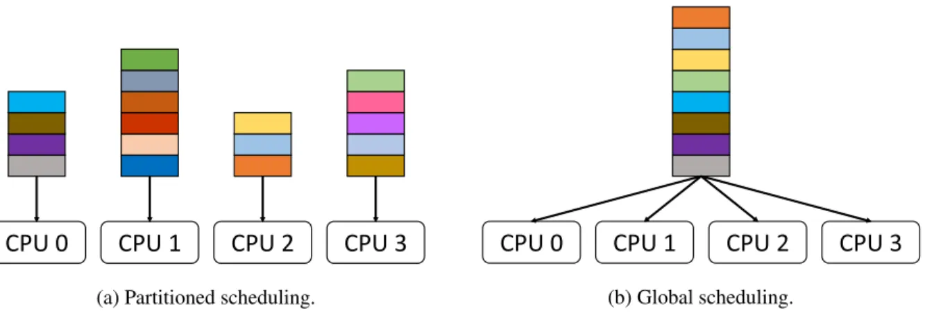
Figure 2.1: Examples of two scheduling approaches on a quad-core platform.
fixed-ordynamic-priority. Fixed-priority schedulers assign the same priority to all jobs of the same task. For example, therate-monotonic (RM)scheduler is a fixed-priority scheduling algorithm where tasks are prioritized by periods,i.e., a shorter period results in a higher priority. Theearliest-deadline-first (EDF) scheduler is a dynamic-priority scheduling algorithm where each job is prioritized by its absolute deadline, with earlier deadlines having higher priority.
We now discuss scheduling approaches in multicore platforms. In this dissertation, we consider partitioned and global schedulers. Figure 2.1 illustrates these two scheduling approaches and ready queues for a system with four processors. A ready queue is a priority-ordered queue of ready jobs that are waiting to be scheduled on a processor. In this figure, a colored box represents a ready job in the queue. Under partitioned scheduling, each processor has a dedicated ready queue, while a single global ready queue is used under global scheduling. Different partitioned and global schedulers are distinguished by how they prioritize jobs. For example, partitioned-EDF (P-EDF) adopts a partitioned approach and uses EDF priorities. Similarly, global-EDF (G-EDF) adopts a global approach and uses EDF priorities.
2.1.3 Schedulability
one exists. Aschedulability testmust be performed to evaluate whether a task system is schedulable under a given scheduling algorithm.
Uniprocessor schedulability. We begin with uniprocessor schedulability. Liu and Layland (1973) showed
that any implicit-deadline periodic task system scheduled by the uniprocessor RM scheduler is HRT-schedul-able if
U ≤n(2n1 −1). (2.3)
This test is onlysufficientbecause task systems exist with utilizations satisfyingn(2n1 −1)< U ≤1that
are feasible to schedule that cannot be deemed unschedulable by the schedulability test in (2.3). Anexact schedulability test always returns true if a task system can be correctly scheduled under a given scheduler. Liu and Layland (1973) also showed that any implicit-deadline periodic task system scheduled by the uniprocessor EDF scheduler is HRT-schedulable if and only if
U ≤1. (2.4)
Uniprocessor EDF is therefore optimal because it always produces a feasible schedule unless the processor is overutilized.
Schedulability on multicore platforms. We now discuss schedulability on multicore platforms consisting
ofmprocessors, in whichm >1. Under partitioned scheduling, as tasks are statically assigned to processors, we can apply a uniprocessor schedulability test to each processor. However, a task assignment problem arises when we evaluate the schedulability of a task system because tasks must be assigned to processors so that no processor is overutilized. This requires solving the bin-packing problem, which is known to be NP-hard in the strong sense (Dhall and Liu, 1978). For example, consider a task system with three identical tasks, τi = (2,3)where1≤i≤3, on a system with two processors. The total utilization of this task system is
implicit-deadline periodic and ordered by decreasing utilization, that is,u1≥u2 ≥. . .≥un. The first-fit
heuristic assigns each taskτito the first processor where it fits. The best-fit heuristic selects the processor
with the lowest free capacity among those with enough capacity to hold the task. The worst-fit heuristic is the inverse of the best-fit heuristic, that is, each taskτi is allocated to the processor with the highest free capacity.
Under global scheduling, themhighest-priority jobs are scheduled at any time. A single ready queue serves all processors in the system under global priority-driven schedulers. Thus, it does not need to solve the bin-packing problem, which causes capacity loss under partitioned scheduling. The schedulability of global scheduling has been investigated by many researchers, resulting in many schedulability tests. In this dissertation, we focus on SRT-schedulability under G-EDF for sporadic task systems as ourMC2framework uses G-EDF for SRT systems. The details of theMC2framework will be discussed in Section 2.2. Devi and Anderson (2005) showed that G-EDF under SRT timing constraints has no capacity loss. In particular, an implicit-deadline sporadic task system under G-EDF is SRT-schedulable with bounded tardiness if the utilization constraints
U ≤m (2.5)
and
∀τi:ui≤1 (2.6)
both hold. The tardinessxiof any job in a sporadic task systemτ under preemptive G-EDF is bounded by
xi=
(P
τj∈E(τ)Cj)−Cmin
m−P
τk∈T(τ)uk
+Ci, (2.7)
whereCminis the smallestCiin the task systemτ,E(τ)is the subset ofm−1tasks inτ with the largestCj
values, andT(τ)is the subset ofm−1tasks inτ with the largestukvalues.
Figure 2.2 shows the schedule of a task system with three identical periodic tasks,τi = (2,3), under
G-EDF on two processors. If there is a tie, we break it by task index. After timet = 3, the schedule settles into a steady pattern. The task system presented in Figure 2.2 is not schedulable under partitioned scheduling, while it is SRT-schedulable under G-EDF. This task system satisfies the task system utilization (Inequality (2.5)) and per-task utilization (Inequality (2.6)) constraints. The tardiness bound of this task system is two time units (Equation (2.7)). In Figure 2.2, we observe that the maximum tardiness of taskτ3is
߬
ଷDeadline Completed Release
߬
ଶ߬
ଵScheduled on CPU 0 Scheduled on CPU 1
time
0 5 10 15
Figure 2.2: Example of bounded tardiness for a task system under G-EDF on two processors.
analytical pessimism. Erickson (2014) improved the analytical tardiness bound by introducing Compliant Vector Analysis (CVA), which uses pseudo-deadlines calledpriority points.
2.1.4 Mixed-Criticality Scheduling
The conventional approach to designing a safety-critical real-time system is to use pessimistic WCET provisioning for higher-criticality tasks, which results in the under-utilization of computational capacity. Vestal (2007) proposed a technique to mitigate such under-utilization of a system for uniprocessor platforms. He observed that the WCETs of higher-criticality tasks are needlessly pessimistic from the perspective of scheduling lower-criticality tasks. Thus, he proposed schedulability tests for mixed-criticality systems to reclaim capacity loss in practice. When checking the schedulability of lower-criticality tasks, less-pessimistic execution times are assumed. To achieve this, multiple WCET values are required for each task: one for its own criticality level and one for every other criticality level. More formally, in a system withLcriticality levels, each task has a WCET specified at every level, andLsystem variants are analyzed: in the Level-l variant, the real-time requirements of all Level-ltasks are verified with Level-l WCETs assumed forall tasks of equal or higher-criticality level. The degree of pessimism in determining WCETs is level-dependent: if Levellis of higher criticality than Levell0, then Level-lWCETs will generally be greater than Level-l0
WͲ&
'Ͳ&
ĞƐƚĨĨŽƌƚ
WͲ&
WͲ&
WͲ&
WhϬ
Whϭ
WhϮ
Whϯ
>ĞǀĞů
>ĞǀĞů
>ĞǀĞů
>ĞǀĞů
ŚŝŐŚĞƌ ;ƐƚĂƚŝĐͿ ƉƌŝŽƌŝƚLJ
ůŽǁĞƌ ;ƐƚĂƚŝĐͿ ƉƌŝŽƌŝƚLJ
Figure 2.3: Scheduling inMC2on a quad-core machine.
2.2 MC2
Vestal’s work led to a significant body of follow-up work. Anderson et al. (2009) proposed a mixed-criticality scheduling approach for multicore platforms that uses a hierarchical scheduling framework called MC2(mixed-criticality on multicore), which provides isolation for tasks of different criticality levels (Mol-lison et al., 2010; Herman et al., 2012; Ward et al., 2013). MC2was the first mixed-criticality scheduling framework for multicore processors. MC2supports four criticality levels, denoted A (highest) through D (lowest), as shown in Figure 2.3. Higher-criticality tasks are statically prioritized over lower-criticality cones. InMC2, tasks at each criticality level can be scheduled by different scheduling algorithms, allowing appropriate schedulers to be used per level. The selected scheduling algorithms for each level are illustrated in Figure 2.3.
Level-A tasks are partitioned and scheduled on each core using a time-triggered table-driven cyclic executive. Tasks are statically assigned to processors, and a dispatching table for each processor is used. As Level-A tasks are the highest-criticality tasks in the system, Level-A tasks are always scheduled when they become eligible. Level-B tasks are also partitioned but are scheduled using a P-EDF scheduler on each processor.1 Level B has the second-highest priority, so any eligible Level-B task will be scheduled when no Level-A task is executing on the same processor. On each processor, the Level-A and -B tasks are required to besimply periodic(all tasks commence execution at time 0 and periods are harmonic), and the Level-B
1
task periods are integer multiples of the Level-A hyperperiod. Level-C tasks are scheduled via a G-EDF scheduler. The G-EDF scheduler is invoked on any processor whenever Level-C tasks are eligible but no higher-criticality tasks are eligible. Level-A and -B tasks are HRT, Level-C tasks are SRT, and Level-D tasks are non-real-time. In this dissertation, we assume that Level D is not present because it is afforded no real-time guarantees.
InMC2, we adopt a measurement-based approach to determiningprovisioned execution times (PETs)2 because work on static timing-analysis tools for multicore machines has not matured to the point of being directly applicable. Moreover, measurement-based processes for determining PETs are often used in practice. As in prior work onMC2(Mollison et al., 2010; Herman et al., 2012; Ward et al., 2013), we assume that Level-C PETs reflect measured average-case execution times (ACETs)(since Level C is SRT) and that Level-B PETs reflect measured WCETs (since Level B is HRT). Further, we assume that Level-A PETs are defined by applying an inflation factor to Level-B PETs (since Level A is of highest criticality).
MC2was originally designed in consultation with colleagues in the avionics industry. A major thesis underlying its design is that Levels A and B would be mostly comprised of quite deterministic “fly-weight” tasks with rather low utilizations; less-deterministic computationally intensive tasks of higher utilization would likely be assigned to Level C.
2.3 Multicore Platforms
In this section, we discuss multicore architectures and considerations in designing real-time systems on multicore platforms. We begin with a discussion of the key components of multicore architectures. We then discuss cross-core interference caused by shared hardware resources.
2.3.1 Processing Units
A multicore platform has two or more processors and hardware resources shared among the processors. A processor is a functional unit that consists of computation units and caches. The multicore platform improves overall performance by running multiple tasks in parallel, while a uniprocessor platform uses time slices to run multiple tasks. Multicore platforms could be implemented via two different configurations: heterogeneous platforms that use more than one kind of processor and homogeneous platforms that have identical processors.
2
In this dissertation, we consider homogeneous multicore platforms in which all processors are running at the same clock speed.
2.3.2 Memory
When a processor runs a task, it needs to access instructions and data stored in memory. Historically, computer systems have hierarchical memory with multiple storage levels.Registersare located inside the processor and typically hold a word of data. Registers are the fastest storage in a system, but they are relatively few in number.Cacheis an intermediate storage between registers andmain memory. Cache was introduced to improve performance by copying frequently accessed instructions and data from main memory into the cache, which is faster but smaller than main memory. Caches are usually organized as multiple levels of caches. Typically, level 1 (L1) caches are split into instruction (L1-I) and data (L1-D) caches, while the level 2 (L2) cache is a unified cache that stores both instructions and data. Some hardware platforms have additional levels (L3 or L4).
Main memory, also known asphysical memory, is connected to processors via amemory busand managed by a memory management unit (MMU), which translatesvirtual memory addressestophysical memory addresses. The mapping between virtual addresses and physical addresses is constructed by the OS and
stored inpage tables. Apageis a fixed-length contiguous block of virtual memory. The MMU divides the virtual address space into pages: a page is the smallest unit of memory management conducted by the OS. Apage frameis the fixed-length contiguous block of physical memory. Main memory consists of multiple DRAM banks that store page frames. In multicore platforms, DRAM banks and memory buses are shared among all processors and accesses to DRAM are controlled by the DRAM controller.
2.3.3 An Example Hardware Platform
WhϬ
>ϭͲ/
ϯϮ<
>ϭͲ
ϯϮ<
Whϯ
>ϭͲ/
ϯϮ<
>ϭͲ
ϯϮ<
>Ϯ
ϭD
͘͘͘
ZD
ĂŶŬϬ
ϭϮϴD
ZD
ĂŶŬϳ
ϭϮϴD
͘͘͘
Figure 2.4: The architecture of quad-core ARM Cortex-A9.
2.4 Shared Hardware Resources
In this section, we discuss cross-core interference that arises from contention for shared hardware resources and previous research into mitigating such interference. We primarily focus on two key components of the memory hierarchy: caches and DRAM banks.
2.4.1 Caches
Way
0 Way1 Way2 ... Way15 Color
0 Color
1 Color
2
...
Color 15 Address Bits [31:0]
Cache Bits [15:12]
[0010]
Figure 2.5: Set-based cache partitioning on the ARM Cortex-A9.
so the current state-of-the-art standard practice in using multicore platforms for safety-critical systems is to disable all but one core, which entails severely underutilizing a system, as mentioned in Chapter 1.
Set-based partitioning. To mitigate cross-core cache evictions, acache partitioningapproach has been
proposed (Kirk, 1989; Bui et al., 2008; Altmeyer et al., 2014). Under cache partitioning, the shared LLC is divided into several partitions, and each task or processor is assigned to disjoint sets of cache lines so that no overlap exists in the LLC in order to eliminate cross-core evictions. Such allocations can be determined by the compiler (Mueller, 1995), or the OS can control the mapping bypage coloring(Kessler and Hill, 1992). Under page coloring, colors are assigned to page frames and corresponding cache lines.3 For example, imagine assigning the color “0” to the first page frame and corresponding cache lines. In a similar way, assign the color “1” to the next page frame and so on. Eventually, such color assignments will wrap, and we will sequence through the same colors again. The coloring process is based on physical memory addresses as depicted in Figure 2.5. In Figure 2.5, four bits are used to assign a color to a page as the LLC has 2,048 cache lines (16 colors) per way. This process ensures that differently colored pages map to different cache lines in the LLC. Thus, accesses to two differently colored pages cannot cause cache conflicts. By using page coloring, we can implementset-basedcache partitioning.
Way-based partitioning. Way-basedpartitioning is also possible by using additional hardware features,
such as cache lockdown, that are available on some platforms. Cache lockdown allows a processor to specify which ways of the cache are locked down. The locked cache ways are protected from being evicted. Way-based partitioning can be achieved by assigning disjoint sets of cache ways to each processor. In other
3
Way
0 Way1 Way2 ... Way15 Color
0 Color
1 Color
2
...
Color 15 CPU 0 Lockdown Register
Lockdown Bits [15:0] [1111 1111 1111 1011]
CPU 0
L2 Cache Lockdown Register
Figure 2.6: Way-based cache partitioning on the ARM Cortex-A9.
words, each processor has its own cache ways to eliminate cross-core evictions. In our platform, cache lockdown is supported by per-processor lockdown registers as depicted in Figure 2.6. In Figure 2.6, only Way 2 is unlocked from CPU 0’s perspective, so CPU 0 can only use Way 2 for allocating cache lines. This can be achieved by setting all bits to 1 except the bit 2.
Prior work on managing caches. Page coloring and cache lockdown techniques are used in recent works
%DQN
&ROXPQV
5
R
Z
V
Z
Ž
ǁ
Ě
ĞĐ
Ž
Ě
Ğƌ
ZŽǁďƵĨĨĞƌ
ŽůƵŵŶĚĞĐŽĚĞƌ $GGUHVVEXV
'DWDEXV
%DQN
%DQN
'5$0
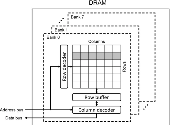
Figure 2.7: The architecture of a DRAM chip that has eight banks.
2.4.2 DRAM Banks
Memory references missed in caches result in a main memory access with longer latency. Figure 2.7 illustrates the architecture of a DRAM chip. A DRAM chip consists of multiple banks, and each bank consists of multiple rows and columns of memory cells. Therow buffer, which stores accessed data, acts as a cache within DRAM. When a read or write operation is issued, the address is decoded by row and column decoders, and then the row buffer transfers data to the data bus. If the corresponding row is found in the row buffer, a row buffer hitoccurs. Otherwise, arow buffer missoccurs, which increases memory-access latency. When row buffer miss occurs, the existing data in the row buffer must be copied back to the bank array, and then the new row is copied into the row buffer. Thus, memory references from different processors may interfere with each other in multicore platforms. Many techniques have been proposed to mitigate such unpredictability caused by row buffer conflicts.
Prior work on mitigating memory contention. One approach to mitigating DRAM bank interference due
proposed a bank-aware memory-allocation framework called PALLOC to mitigate bank-level interference by partitioning DRAM banks. In addition to bank partitioning, managing the DRAM controller has also been considered as a method to reduce interference due to bus contention. Yun et al. (2013) presented a framework called MemGuard to limit memory bandwidth by suspending tasks that use too much memory bandwidth within a given interval. However, these papers do not consider mixed-criticality systems.
2.4.3 Unmanaged Hardware Resources
The LLC and DRAM banks are not the only source of cross-core interference. Other hardware resources such as L1 caches, translation lookaside buffers (TLBs) (Panchamukhi and Mueller, 2015), memory con-trollers (Hassan et al., 2015; Guo and Pellizzoni, 2017), memory buses (Muench et al., 2014; Seetanadi et al., 2017), or cache-related registers (Valsan et al., 2016) can be contention sources. In this dissertation, we do not manage these shared hardware resources. However, we assume a measurement-based approach to determining PETs, so such uncontrolled resources are implicitly considered when determining PETs as we measure execution times under the presence of contention for such uncontrolled resources. We also assume that sufficient measurements are taken to cover the worst-case behavior of all tasks with respect to unmanaged resources.
2.5 LITMUSRT
Carolina at Chapel Hill and Max Planck Institute for Software Systems since 2006 (Calandrino et al., 2006; Brandenburg, 2011; LITMUSRT Project, 2018). LITMUSRT provides interfaces within the kernel that facilitate the prototyping of real-time scheduling algorithms, and it is a useful experimental platform for real-time systems
2.6 Summary
CHAPTER 3: ENABLING HARDWARE MANAGEMENT INMC24
In this chapter, we present the design of hardware management that we added to the original MC2 framework. Ward et al. (2013) proposed shared LLC management techniques in MC2. However, the techniques proposed by them require prefetching every page of the next task and using synchronization protocols. They also did not support criticality-aware cache management. In this dissertation, we propose a holistic way to manage shared hardware resources, which does not require prefetching pages and using synchronization protocols to manage the shared LLC. We focus on managing the shared LLC and DRAM banks in the hardware platform depicted in Figure 2.4. The resultingMC2framework is highly configurable and allows us to explore tradeoffs between sharing and isolation in a criticality-cognizant way. The hardware-management techniques inMC2support DRAM bank partitioning, and fine-grained cache partitioning, which combines set-based and way-based cache partitioning. We present several resource allocation strategies and evaluate each strategy that we propose. We also evaluate the efficacy of our combination of hardware management and mixed-criticality provisioning by conducting a large-scale overhead-aware schedulability study.
This chapter is organized as follows. We begin by presenting the hardware-management techniques we employ. We then discuss resource allocation strategies. Following this discussion, we describe the details of our implementation inMC2. We then present an evaluation of our techniques. Finally, we conclude this chapter.
3.1 Hardware Management Techniques
The goal of managing shared hardware is to reduce capacity loss on multicore platforms. This goal can be achieved by providing criticality-cognizant task isolation, which removes or mitigates cross-core
4Contents of this chapter previously appeared in preliminary form in the following papers:
Kim, N., Ward, B., Chisholm, M., Anderson, J., and Smith, F. D. (2017b). Attacking the One-Out-Of-mMulticore Problem by Combining Hardware Management with Mixed-Criticality Provisioning.Real-Time Systems, 53(5):709–759;
interference caused by contention for shared resources. There are important choices to make in providing criticality-cognizant task isolation. First, we must decide how to configure the shared LLC and DRAM banks for each criticality level. For example, we can assign a dedicated partition to each criticality level for strong task isolation or we may allow lower-criticality tasks to share the LLC and DRAM banks. Second, we must determine the size of each partition of the LLC and DRAM banks for better schedulability. Therefore, we design and implement our hardware management framework to support two abilities:
1. The framework can assign LLC and DRAM bank partitions at each criticality level independently. 2. The framework can freely change the size of each partition.
The first ability enables us to explore tradeoffs between sharing and isolation with respect to the LLC and DRAM banks. The second ability enables us to optimize the utilization of system resources in terms of schedulability. In order to provide these two properties, we designed and implemented a kernel module that partitions the shared LLC and DRAM banks and a user interface to configure each partition. Partitioning the shared LLC and DRAM banks can be achieved by managing page allocations in the OS. As we discussed in Chapter 2, we can assign distinct sets of pages to tasks in which two differently colored pages cannot cause conflicts in the shared LLC and DRAM banks.
3.1.1 Cache Partitioning
We now describe the design of cache partitioning in detail. We begin by explaining way-based partitioning. We then describe set-based partitioning.
Way-based partitioning. For way-based partitioning, we require hardware features that manage way
allocations in the shared LLC. Our platform provides a cache lockdown mechanism calledlockdown by master. Each processor has a dedicated per-processor cache lockdown register. The lockdown register defines
ϮϵϮϴϮϳ Ϭ
ĂŶŬďŝƚƐϮϵ͗Ϯϳ
ϭϱϭϰϭϯϭϮ
ŽůŽƌďŝƚƐϭϱ͗ϭϮ ŝƚƐ
(a) Bank interleaving is off.
Ϯϵ Ϭ
ĂŶŬďŝƚƐϭϱ͗ϭϯ ϭϱϭϰϭϯϭϮ
ŽůŽƌďŝƚƐϭϱ͗ϭϮ ŝƚƐ
(b) Bank interleaving is on.
Figure 3.1: Physical address decoding of NXP i.MX6 processor.
next task to execute. Thus, we can achieve way-based cache partitioning according to the criticality of the next task.
Set-based partitioning. Set-based partitioning requires a hardware platform featuring the shared LLC
organized as a physically tagged cache. Figure 3.1 shows the physical address decoding of our platform when bank interleaving is on and off. Details concerning bank interleaving will be discussed in Section 3.1.2. As discussed in Section 2.4.1, set-based partitioning can be achieved by page coloring. The address bits [15:12] determine the color of the shared LLC, which controls the mapping between cache lines and physical page frames. Once physical page frames are allocated to a task, the mapping between virtual addresses and physical addresses cannot be modified unless pages are swapped out to disk. In this dissertation, we do not allow swapping to disk at runtime, which means that all pages of a real-time task must be reside in memory until the task exits. Now, we can imagine two approaches to assign colored pages to tasks: 1) Allocate colored pages to a task when it is created. 2) Migrate pages before a task starts executing.
concluded that the former approach is not feasible due to difficulties in implementation effort, efficiency, and stability, while the latter approach is relatively easy to implement by adding a system call that migrates pages in the kernel. Thus, we chose to adopt the latter approach. We migrate original pages of all tasks in a task system to properly colored pages before the task system begins executing. However, some pages are not eligible to migrate. If pages are shared by other tasks or the kernel, they are not migratable. In this chapter, we assume that all pages are migratable,i.e., no shared pages exist in tasks. We will discuss techniques to handle different types of shared pages in Chapter 4.
3.1.2 DRAM Bank Partitioning
The OS does not consider DRAM banks when allocating memory. In the kernel, memory is considered as a single resource. This could cause cross-core contention in DRAM banks if all processors are accessing the same bank at the same time. To make DRAM banks more predictable, we divide DRAM banks into multiple partitions and assign a dedicated partition to each processor so that memory accesses from different processors do not cause cross-core interference. To implement DRAM bank partitioning, the address mapping information between DRAM banks and physical page frames is required. Fortunately, the architecture manual of our platform provides the exact information about physical address decoding as depicted in Figure 3.1. As our platform has eight DRAM banks, three bits in the physical address determine the location of a particular DRAM bank. Since DRAM bank partitioning can be achieved in the same manner as set-based cache partitioning, we use the same mechanism, migrating pages, to partition DRAM banks.
Bank interleaving. Bank interleaving is a technique that parallelizes memory accesses to improve memory
͘͘͘
ĂŶŬϬ ĂŶŬϭ ĂŶŬϮ ĂŶŬϳ
W&EϬ ;ŽůŽƌϬͿ W&Eϭ ;ŽůŽƌϭͿ W&EϮ ;ŽůŽƌϮͿ ͘͘͘ W&Eϭϱ ;ŽůŽƌϭϱͿ W&Eϭϲ ;ŽůŽƌϬͿ ͘͘͘ W&EϯϮϳϲϳ ;ŽůŽƌϭϱͿ W&EϯϮϳϲϴ ;ŽůŽƌϬͿ W&EϯϮϳϲϵ ;ŽůŽƌϭͿ W&EϯϮϳϳϬ ;ŽůŽƌϮͿ ͘͘͘ W&EϯϮϳϴϯ ;ŽůŽƌϭϱͿ W&EϯϮϳϴϰ ;ŽůŽƌϬͿ ͘͘͘ W&Eϲϱϱϯϱ ;ŽůŽƌϭϱͿ W&Eϲϱϱϯϲ ;ŽůŽƌϬͿ W&Eϲϱϱϯϳ ;ŽůŽƌϭͿ W&Eϲϱϱϯϴ ;ŽůŽƌϮͿ ͘͘͘ W&Eϲϱϱϱϭ ;ŽůŽƌϭϱͿ W&EϲϱϱϱϮ ;ŽůŽƌϬͿ ͘͘͘ W&EϵϴϯϬϯ ;ŽůŽƌϭϱͿ W&EϮϮϵϯϳϲ ;ŽůŽƌϬͿ W&EϮϮϵϯϳϳ ;ŽůŽƌϭͿ W&EϮϮϵϯϳϴ ;ŽůŽƌϮͿ ͘͘͘ W&EϮϮϵϯϵϭ ;ŽůŽƌϭϱͿ W&EϮϮϵϯϵϮ ;ŽůŽƌϬͿ ͘͘͘ W&EϮϲϮϭϰϯ ;ŽůŽƌϭϱͿ
Figure 3.2: Page layout in DRAM banks when bank interleaving is off.
͘͘͘
ĂŶŬϬ ĂŶŬϭ ĂŶŬϮ ĂŶŬϳ
W&EϬ ;ŽůŽƌϬͿ W&Eϴ ;ŽůŽƌϭͿ W&Eϭϲ ;ŽůŽƌϬͿ ͘͘͘ W&EϮϲϮϭϮϴ ;ŽůŽƌϬͿ W&Eϭ ;ŽůŽƌϮͿ W&Eϵ ;ŽůŽƌϯͿ W&Eϭϳ ;ŽůŽƌϮͿ ͘͘͘ W&EϮϲϮϭϮϵ ;ŽůŽƌϮͿ W&EϮ ;ŽůŽƌϰͿ W&EϭϬ ;ŽůŽƌϱͿ W&Eϭϴ ;ŽůŽƌϰͿ ͘͘͘ W&EϮϲϮϭϯϬ ;ŽůŽƌϰͿ W&Eϳ ;ŽůŽƌϭϰͿ W&Eϭϱ ;ŽůŽƌϭϱͿ W&EϮϯ ;ŽůŽƌϭϰͿ ͘͘͘ W&EϮϲϮϭϯϱ ;ŽůŽƌϭϰͿ W&EϮϲϮϭϯϲ ;ŽůŽƌϭͿ W&EϮϲϮϭϯϳ ;ŽůŽƌϯͿ W&EϮϲϮϭϯϴ ;ŽůŽƌϱͿ W&EϮϲϮϭϰϯ ;ŽůŽƌϭϱͿ
Figure 3.3: Page layout in DRAM banks when bank interleaving is on.
3.2 Resource Allocation Strategy
In this section, we begin by describing our LLC allocation strategies considered in this chapter. We then describe DRAM allocation strategy and the benefits of disabling bank interleaving.
3.2.1 LLC Allocation
The LLC-allocation strategies studied in this dissertation are depicted in Figure 3.4. In this figure, LLC boundaries indicated by double lines are settable parameters. We categorize these allocation strategies into three separatevariants.
Variant 1, shown in Figure 3.4 (a), ensures strong isolation guarantees for Level-A and -B tasks while allowing for fairly permissive hardware sharing for Level-C tasks when used in combination with our DRAM-allocation strategy. As seen, Level C and the OS share a subsequence of the available LLC ways and all LLC colors because the OS pages may have more than four physically contiguous pages. As noted in Section 2.2, we assume that Level-C tasks (being SRT) are provisioned on an average-case basis. Under this assumption, LLC sharing with the OS should not be a major concern. The remaining LLC ways are partitioned among Level-A and -B tasks on a per-processor basis. That is, the Level-A and -B tasks on a given core share a partition. Each of these partitions is allocated a quarter of the available colors, as depicted. This scheme ensures that Level-A and -B tasks do not experience LLC interference due to tasks on other processors (spatial isolation). LLC interference between Level-A and -B tasks on the same processor may occur, but this interference only affects Level-B tasks, as Level-A tasks execute with higher priority. However, it may still be desirable to limit this interference. As a consequence, different LLC areas are allocated to Level A and B within a processor partition, but these areas may overlap.5
Variants 2 and 3, depicted in insets (b) and (c) of Figure 3.4, are analyzed in later chapters to characterize the advantages and disadvantages of isolation and sharing for each criticality level. In Variant 2, the LLC area allocated to Level C and the OS is partitioned by way on a per-processor basis. This variant provides stronger isolation guarantees to Level-C tasks but reduces the LLC area that such a task can utilize. In Variant 3, Level-A and -B tasks are not partitioned by processor, thus giving each Level-A and -B task access to all
5
ϰŽůŽƌƐ
ϭϲtĂLJƐ
ϰŽůŽƌƐ
ϰŽůŽƌƐ
ϰŽůŽƌƐ
>>;>ϮͿ >ĞǀĞů
ĂŶĚ K^ WhϬ
>ĞǀĞů
WhϬ >ĞǀĞů
Whϭ >ĞǀĞů
Whϭ >ĞǀĞů
WhϮ >ĞǀĞů
WhϮ >ĞǀĞů
Whϯ >ĞǀĞů
Whϯ >ĞǀĞů
(a) Variant 1 (HRT-isolated and SRT-shared LLC).
ϰŽůŽƌƐ
ϭϲtĂLJƐ
ϰŽůŽƌƐ
ϰŽůŽƌƐ
ϰŽůŽƌƐ
>>;>ϮͿ WhϬ
>ĞǀĞů ĂŶĚ
K^ WhϬ
>ĞǀĞů
WhϬ >ĞǀĞů
Whϭ >ĞǀĞů
Whϭ >ĞǀĞů
WhϮ >ĞǀĞů
WhϮ >ĞǀĞů
Whϯ >ĞǀĞů
Whϯ >ĞǀĞů
Whϭ >ĞǀĞů ĂŶĚ
K^ WhϮ >ĞǀĞů ĂŶĚ
K^ Whϯ >ĞǀĞů ĂŶĚ
K^
(b) Variant 2 (All-isolated LLC).
ϭϲŽůŽƌƐ
ϭϲtĂLJƐ
>>;>ϮͿ >ĞǀĞů
ĂŶĚ K^ >ĞǀĞů
ůůŽƌĞƐ
>ĞǀĞů ůůŽƌĞƐ
(c) Variant 3 (All-shared LLC).
ZD ĂŶŬϬ
>ĞǀĞů ĂŶĚK^
ZD ĂŶŬϭ
>ĞǀĞů ĂŶĚK^
ZD ĂŶŬϮ
>ĞǀĞů ĂŶĚK^
ZD ĂŶŬϯ
>ĞǀĞů ĂŶĚK^
ZD ĂŶŬϰ WhϬ >ĞǀĞůƐ ĂŶĚ
ZD ĂŶŬϱ Whϭ >ĞǀĞůƐ ĂŶĚ
ZD ĂŶŬϲ WhϮ >ĞǀĞůƐ ĂŶĚ
ZD ĂŶŬϳ Whϯ >ĞǀĞůƐ ĂŶĚ
Figure 3.5: DRAM allocation strategy.
16 colors. This reduces isolation guarantees at Levels A and B, but increases the LLC area that Level-A and -B tasks can utilize.
The specific number of LLC ways assigned to each allocated LLC area is a tunable parameter that affects the execution times of tasks, as demonstrated later in Section 3.4. We determine values for these parameters on a per-task-system basis using optimization techniques proposed by Chisholm et al. (2015). The optimization techniques seek to minimize a task system’s Level-C utilization while ensuring schedulability at all criticality levels.
3.2.2 DRAM Allocation and Bank Interleaving
Our DRAM allocation strategy is depicted in Figure 3.5. To provide strong isolation for HRT tasks, each processor has a dedicated DRAM bank for Level-A and -B tasks. Level-C tasks and the OS share the remaining four banks so that SRT tasks and the OS do not affect Level-A or -B tasks with respect to DRAM accesses. At memory initialization time, the OS reserves a range of physical pages used by the kernel and peripheral devices. The arrangement of the OS kernel code and data in our platform is presented in Figure 3.6. The reserved pages used by the kernel code and data are not movable and will never be swapped out. If we enable bank interleaving, such pages are spread across DRAM banks as shown in Figure 3.3, which may cause contention in Level-A and -B banks. However, with interleaving disabled, we can isolate the reserved pages from Level-A and -B tasks because the reserved pages are located in Bank 0.
3.3 Implementation
ZĞƐĞƌǀĞĚĨŽƌ ƉĞƌŝƉŚĞƌĂůƐ
ϬdžϬϬϬϬϬϬϬϬ ϬdžϭϬϬϬϬϬϬϬ Ϭdžϰ&&&&&&&
^LJƐƚĞŵZD
Ϭdžϰ&&&&&&& ϬdžϭϬϬϬϬϬϬϬ ϬdžϭϬϬϬϴϬϬϬ
<ĞƌŶĞůĐŽĚĞ ;.textͿ
ϬdžϭϬĚϴϬϬϬϬ
<ĞƌŶĞůĚĂƚĂ ;.dataн.bssͿ
ϭϬϮϰD ϬD
ϭϮϴD;ĂŶŬϬͿ
Figure 3.6: The arrangement of the kernel code and data in memory.
management inMC2. We then discuss theMC2task scheduler and a system call that migrates pages inMC2. We also discuss the coarse-grained OS isolation provided by ourMC2framework.
3.3.1 General Information
The hardware management framework consists of two key components: a mixed-criticality task scheduler and a resource partitioning module. We implemented these components as an extension to LITMUSRT, version 2015.1, which is based upon the 4.1.3 Linux kernel.6
3.3.2 MC2Task Scheduler
Linux can use different scheduling algorithms to schedule different types of tasks by introducingscheduler classes. The base scheduler iterates over each scheduler class in order of priority. The highest priority
scheduler class that has a runnable process picks the next task to run. LITMUSRT introduces a new scheduler class,SCHED LITMUS, to schedule real-time tasks. TheSCHED LITMUSclass has the highest priority of all classes, so real-time tasks are guaranteed to have priority over normal Linux tasks. In LITMUSRT, a new scheduling algorithm can be added toSCHED LITMUSas a scheduler plugin. We implemented our MC2scheduler as a plugin to LITMUSRT. We implemented three different scheduling policies to schedule mixed-criticality tasks becauseMC2has three criticality levels that require real-time constraints.7
6
The code is available athttps://wiki.litmus-rt.org/litmus/Publications.
7Level-D tasks are non-real-time. Thus, theMC2scheduler does not schedule Level-D tasks. Such tasks can be scheduled by Linux
LITMUSRT provides several real-time scheduling algorithms as scheduler plugins. TheP-RES (par-titioned uniprocessor reservation)scheduler in LITMUSRT supports the partitioned cyclic-executive and P-EDF scheduling algorithms. However, asMC2uses G-EDF for scheduling Level-C tasks, we extended the P-RES scheduler to supportMC2tasks. In P-RES, areservationis a schedulable entity that may have more than one task. Each reservation has abudget(i.e., an OS-enforced execution time) and areplenishment period. This reservation structure is used to realize budget enforcement, which is required to implement
MC2(Mollison et al., 2010; Herman et al., 2012).
InMC2, we modified the structure of a reservation to have only one task. The budget of a reservation is equal to the associated task’s PET at its own criticality level and the replenishment period is equal to the task’s period. To statically prioritize each criticality level, we implemented a set of reservations, known as acontainer(in other literature, called aserver). Each processor has a set of reservations, called alocal container, that has Level-A and -B reservations for tasks assigned to that processor. In a local container,
Level-A reservations are prioritized over Level-B reservations. Thus, the local container can serve as both a dispatching table for the cyclic executive and a ready queue for Level-B tasks. For Level-C tasks, we implemented a set of reservations, called aglobal container, that is shared among all mprocessors. Reservations in the global container are sorted in the order of deadlines. When theMC2scheduler is invoked to select the next task to run on the current processor, it first selects a container. Then, the scheduler selects the next task from the selected container, according to a scheduling algorithm associated with that particular container.
3.3.3 Allocating Colored Pages to Tasks
As we discussed in Section 3.1, a physical address of a page determines both its LLC color and DRAM bank. Therefore, we can achieve set-based partitioning and DRAM bank partitioning by modifying the memory-management system in Linux. We begin by describing the memory-management system in Linux. We then present our modifications to this system.
Memory management in Linux. In Linux, physical pages are managed and allocated by the buddy