International Journal of Science Engineering and Advance Technology (IJSEAT)
ISSN 2321-6905, Vol. 7, Issue 9, September -2019
Analytical Investigations of Capillary Tubes with Mixture
Refrigerants Used In Refrigerators
1
Sree Ramachandra murthy.K.2Dr.T. Dharmaraju, Ph.D.
1PG Student, Adarsh College of Engineering, Chebrolu. 2Professor,Adarsh College of Engineering, Chebrolu.
1,2Department of Mechanical Engineering
Abstract: Capillary tubes are used as expansion device
in low capacity refrigeration machines like domestic refrigerators and window type air conditioners. The advantages of the capillary tube over other development gadgets are basic, cheap and cause blower to begin at low torque as the weight over the slender cylinder adjust during the off-cycle. The flow attributes of refrigerants through narrow cylinders have been considered broadly in recent decades, by both theory and experiment it is observed that , a large portion of these examinations for the most part centered around straight capillary tube.
The R174A refrigerant and azeotropic mixture of R30 & R160 is made with R160 concentrations of 0%, 20%, 40%, 60%, 80% and 100% in R30 and it is used in a Refrigeration unit with different flow rates by fixing the other input parameters constant. In this thesis the analysis it is known that higher flow rates of the refrigerant mixture increase the heat transfer rates but in the expense of higher work consumption which will affect the coefficient of performance of the refrigerant unit which is not advisable to use since the work utilization of the good refrigeration unit should be lesser for unit of refrigeration.CFD analysis to determine the heat transfer coefficient, mass flow rate, heat transfer rate, pressure drop at different number coils (30 and 40 coils).
Key words- capillary tube, refrigerant, heat transfer.
1. INTRODUCTION
A straightforward vapors pressure refrigeration framework comprises of primarily five segments in particular blower, condenser, extension gadget, evaporator and a channel/drier. The accompanying investigation is engaged towards discovering the impact of the hairlike cylinder on the exhibition of the refrigeration framework.
1.1 CAPILLARY TUBE
A capillary tube is a long, slender container of steady measurement. "Capillary" is a misnomer since surface strain isn't significant in refrigeration application of slim cylinders.
Revised Manuscript received on September 10, 2019 *Corresponding Author
Sree Ramachandra murthy
mail id- [email protected]
Commonplace cylinder distances across of refrigerant slim tube strange from 0.5 mm to 3 mm and the length ranges from 1.0 m to 6 m. The weight decrease in a fine cylinder happens because of the accompanying two factors:
1. The refrigerant has to overcome the frictional opposition offered by tube walls. This prompts some weight drop, and
2. The fluid refrigerant flashes (vanishes) into blend of fluid and vapors its weight decreases. The thickness of vapor is not as much as that of the fluid. Subsequently, the normal thickness of refrigerant reductions as it flows in the tube. The mass stream rate and cylinder width (subsequently zone) being constant, the speed of refrigerant increments since = ρVA. The expansion in speed or increasing speed of the refrigerant additionally requires weight drop[1-7].
1.2 BALANCE POINT OF COMPRESSOR AND CAPILLARY TUBE
The compressor and the capillary tube, under enduring state must touch base at some suction and release weights, which permits a similar mass stream rate through the blower and the slender cylinder. This state is known as the parity point. Condenser and evaporator weights are immersion weights at comparing condenser and evaporator temperatures. Figure 24.1 shows thevariation of mass stream rate with evaporator weight through the blower and the hairlike cylinder for three estimations of condenser temperatures in particular, 30°, 40° and50°C.
2. MODELLING 2.1 Introduction to CAD
Computer-aided design (CAD), otherwise called computer-aided design and drafting (CADD), is the utilization of PC innovation for the procedure of plan and structure documentation. PC Aided Drafting portrays the way toward drafting with a PC. CADD programming, or conditions, give the client input-apparatuses to streamline configuration forms; drafting, documentation, and assembling forms. CADD yield is frequently as electronic documents for print or machining tasks. The advancement of CADD-based programming is in direct relationship with the procedures it looks to conserve; industry-based programming (development, producing, and so forth.) commonly utilizes vector-based (straight) conditions though realistic based programming uses raster-based (pixelated) situations.
2.2Introductionto PRO/ENGINEER
Master/ENGINEER Wildfire is the standard in 3D item plan, including industry-driving profitability instruments that advance accepted procedures in structure while guaranteeing consistence with your industry and friends gauges. Coordinated Pro/ENGINEER CAD/CAM/CAE arrangements enable you to structure quicker than at any other time, while amplifying development and quality to at last make outstanding items.
Client prerequisites may change, and time weights may keep on mounting, however your item configuration needs continue as before - paying little heed to your venture's extension, you need the incredible, simple to-utilize, moderate arrangement that Pro/ENGINEER gives.
2.2.1 Benefits PRO/ENGINEER Wildfire
Unsurpassed geometry creation capabilities allow superior product differentiation and manufacturability
Fully integrated applications allow you to develop everything from concept to manufacturing within one application
Automatic propagation of design changes to all downstream deliverables allows you to design with confidence
Complete virtual simulation capabilities enable you to improve product performance and exceed product quality goals
2.3ANSYS Software
ANSYS is an Engineering Simulation Software (computer aided Engineering). Its tools cover Thermal, Static, Dynamic, and Fatigue finite element analysis
development of the product. The company was founded in 1970 by Dr.John A. Swanson as Swanson Analysis Systems, Inc. SASI. Its primary purpose was to develop and market finiteelement analysis software for structural physics that could simulate static (stationary), dynamic (moving) and heat transfer (thermal) problems.
2.3.1 Benefits of ANSYS
The ANSYS advantage and benefits of using a modular simulation system in the design process are well documented. According to studies performed by the Aberdeen Group, best-in-class companies perform more simulations earlier. As a leader in virtual prototyping, ANSYS is unmatched in terms of functionality and power necessary to optimize components and systems.
The ANSYS advantage is well-documented. 2.3.2Structural Analysis
Structural analysis is probably the most common application of the finite element method. The term structural (or structure) implies not only civil engineering structures such as ship hulls, aircraft bodies, and machine housings, as well as mechanical components such as pistons, machine parts, and tools.
2.3.3 Types of Structural Analysis
Different types of structural analysis are: Static analysis
Modal analysis Harmonic analysis
Transient dynamic analysis Spectrum analysis
Bucking analysis
Explicit dynamic analysis
2.3.4 Static Analysis
Static examination computes the impacts of consistent stacking conditions on a structure, while overlooking inactivity and damping impacts, for example, those brought about by time fluctuating burdens. A static examination can, in any case, incorporate enduring idleness loads, (for example, gravity and rotational speed), and time-fluctuating burdens that can be approximated as static identical burdens, (for example, the static equal breeze bone-dry seismic loads normally characterized in many construction laws).
International Journal of Science Engineering and Advance Technology (IJSEAT)
ISSN 2321-6905, Vol. 7, Issue 9, September -2019
2.4 Introduction to CFD
Computational liquid elements, generally abridged as CFD, is a part of liquid mechanics that utilizations numerical techniques and calculations to take care of and investigate issues that include liquid streams. PCs are utilized to play out the counts required to mimic the communication of fluids and gases with surfaces characterized by limit conditions. With rapid supercomputers, better arrangements can be accomplished. Progressing exploration yields programming that improves the precision and speed of complex reproduction situations, for example, transonic or violent streams. Introductory test approval of such programming is performed utilizing a breeze burrow with the last approval coming in full-scale testing, for example flight tests.
a)R-30 Properties
Density = 1326.6 kg/m3 Specific heat = 1043.0 j/kg/k
Thermal conductivity = 0.0042 w/m-k Viscosity = 0.000279 kg/m-s
b)R-160 Properties
Density = 921.0 kg/m3 Specific heat = 1023.0 j/kg/k
Thermal conductivity = 0.0337 w/m-k Viscosity = 0.00043 kg/m-s
c)Density of Nano FluidFormule:
ρnf=ϕ×ρs+ [(1-ϕ) ×ρw]
d)Specific Heatof Nano Fluid:
Cpnf= × ×
( )( × )
× ( )×
e)Viscosity of Nano Fluid:
µnf=µw(1+2.5ϕ)
Volum e fractio
n (ɸ)
Densit y (kg/m3
)
Specific heat
(j/kg-k)
Thermal conductivi
ty (w/m-k)
Viscosity (kg/m-s)
0.2 1245.4
8
1040.042 0.0076 0.000418
5
0.4 1164.3
6
1036.67206 0.011180
8
0.000558
0.6 1083.2
4
1.32.7972 0.019106 0.000697
5
0.8 1002.1
2
1028.2951 0.038677 0.000837
Table 2.1 Properties of refrigerants 3. ANALYSIS
The aim is to find better performance of differentRefrigerants (R174a,R160,0.2,0.4,0.6,0.8 volume fractions) that are flowing through different capillary tubes(30&40coils).For this study ANSYS is used for CFD simulations and PRO/ENGINEERING is used for modelling.Here in this design analysis using 2 different models of capillary tubes(30&40 coils).
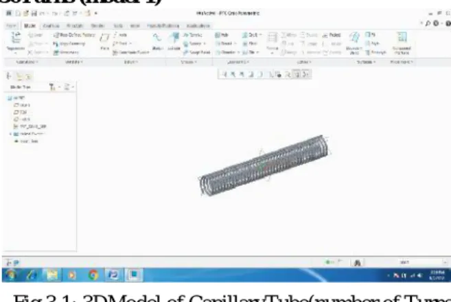
3.1Part Modelling: 3DModel of Capillary Tube: 30Turns (model 1)
Fig 3.1: 3DModel of CapillaryTube(number of Turns 30)(model 1)
3.2 Part Modelling: 3DModel of Capillary Tube: 40Turns (model 2)
Fig 3.2:3DModel of CapillaryTube(number of Turns 40)
(model 2)
3.3 CFD analysis of helically coiled capillary tubes
3.3.1Number of Coils-30(ansys model-1)
→→Ansys → workbench→ select analysis system → fluid flow fluent→ double click
→→ select mesh on work bench → right click →edit → select mesh on left side part tree → right click → generate mesh→
Fig3.3: CFD analysis of helically coiled capillary
tubes(no.of turns-30,ansys model-1)
3.3.2CFD Analysis -Meshed viewNumber of
Coils-30(ansys model-1)
Fig3.4: CFD analysis meshed view (no.of turns-30)
The model is designed with the help of pro-e and then import on ANSYS for Meshing and analysis. The analysis by CFD is used in order to calculating pressure profile and temperature distribution. For meshing, the fluid ring is divided into two connected volumes. Then all thickness edges are meshed with 360 intervals. A tetrahedral structure mesh is used. So the total number of nodes and elements is 6576 and 3344. Select faces → right click → create named section → enter name→ water inlet
Select faces → right click→ create named section → enter name→ water outlet
3.3.3CFD Analysis -fluid inlet condition (no.of turns-30)(ansys model-1)
Fig3.5: CFD Analysis-fluid inlet condition (no.of
turns-30)(ansys model-1)
3.3.4CFD Analysis -fluid out let condition (no.of turns-30)(ansys model-2)
Fig3.6: CFD Analysis Fluid outlet condition (no.of turns-40,ref.-174a)(ansys model-2)
Model→ energy equation → on. Viscous→ edit → k- epsilon Enhanced Wall Treatment→ ok
Materials → new → create or edit → specify fluid material or specify properties→ ok
Select air and water
Boundary conditions → select water inlet → Edit → Enter pressure → 20 bar and Inlet Temperature – 323.3K
Solution → Solution Initialization → Hybrid Initialization→done
Run calculations → no of iterations = 50 → calculate → calculation complete
→→ Results → graphics and animations → contours → setup
→→ select mesh on work bench → right click →edit → select mesh on left side part tree → right click → generate mesh→
Fig3.3: CFD analysis of helically coiled capillary
tubes(no.of turns-30,ansys model-1)
3.3.2CFD Analysis -Meshed viewNumber of
Coils-30(ansys model-1)
Fig3.4: CFD analysis meshed view (no.of turns-30)
The model is designed with the help of pro-e and then import on ANSYS for Meshing and analysis. The analysis by CFD is used in order to calculating pressure profile and temperature distribution. For meshing, the fluid ring is divided into two connected volumes. Then all thickness edges are meshed with 360 intervals. A tetrahedral structure mesh is used. So the total number of nodes and elements is 6576 and 3344. Select faces → right click → create named section → enter name→ water inlet
Select faces → right click→ create named section → enter name→ water outlet
3.3.3CFD Analysis -fluid inlet condition (no.of turns-30)(ansys model-1)
Fig3.5: CFD Analysis-fluid inlet condition (no.of
turns-30)(ansys model-1)
3.3.4CFD Analysis -fluid out let condition (no.of turns-30)(ansys model-2)
Fig3.6: CFD Analysis Fluid outlet condition (no.of turns-40,ref.-174a)(ansys model-2)
Model→ energy equation → on. Viscous→ edit → k- epsilon Enhanced Wall Treatment→ ok
Materials → new → create or edit → specify fluid material or specify properties→ ok
Select air and water
Boundary conditions → select water inlet → Edit → Enter pressure → 20 bar and Inlet Temperature – 323.3K
Solution → Solution Initialization → Hybrid Initialization→done
Run calculations → no of iterations = 50 → calculate → calculation complete
International Journal of Science Engineering and Advance Technology (IJSEAT)
ISSN 2321-6905, Vol. 7, Issue 9, September -2019
3.4 CFD analysis of helically coiled capillary tubes:Results for number of turns-30
1 flowingfluid:R-174a:
Fig 3.7: Static pressure(pascal)(For fluid R174a and number of turns-30)
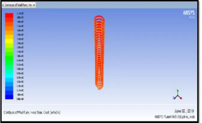
Fig 3.8: Heat transfer coefficient(W/m2-k)(For fluid R174a and number of turns-30)
Fig 3.9: Static Pressure(pascal)(For fluid R174a and number of turns-30)
3.5 CFD analysis of helically coiled capillary tubes: Results for number of turns-40
flowingFluid:R174a
Fig3.10: Static pressure(Pascal)( For fluid R174a and number of turns-40)
Fig 3.11: Heat transfer coefficient (W/m2-K)( For fluid R174a and number of turns-40) 3.6 Thermal Analysis of Helical Capillary Tube
Fig 3.12: Temperature(ºC)(foraluminum alloy7475,no.of.turns-30)
4.RESULT
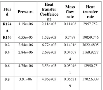
Table 4.1:CFD Analysis results for Helical capillary tube withnumber of turn-30 coils:
Flui
d Pressure
Heat transfer Coeffeiece
nt
Mass flow rate
Heat transfer
rate
R174
A
1.15e+06 2.11e+03 0.11408 2957.752
R160 6.55e+05 1.52e+03 0.7497 19059.746
0.2 2.54e+06 6.77e+02 0.14016 3622.4805
0.4 2.84e+06 2.69e+03 0.04507
4
1160.9277
0.6 4.75e+06 3.53e+03 0.05046
1
12950.75
0.8 3.91+06 4.86e+03 0.06621
9
1702.6309
Table 4.2: CFD Analysis results for Helical capillary tube with number of turn-40 coils:
Fluid Pressur e
Heat transfer Coeffeiece
nt
Mass flow rate
Heat transfer
rate
R174
A 1.66e+06 7.90e+03
0.0800332
1
2183.562
5
R160 2.25e+04 6.34e+01 0.0871749 9
2773.596
9
0.2 3.80e+05 1.43e+01 0.0804915 23420.05 7
0.4 1.33e+05 2.09e+01 0.7261149 15416.98 4
0.6 8.34e+05 3.59e+01 0.2211061 8
5625.289
1
0.8 2.44e+06 7.27e+01 0.0705150 6
1880.968
8
From table:5.1:CFD Analysis results for different fluids in helical capillary tube with number of turn- 30, it is found that Pressure variation is high in 0.6 vol.fraction fluid, Heat transfer co efficient is high in0.8 vol.fraction fluid,Mass flow rate,is high in R160, Heat transfer rate is high in R160 when compared to other fluids
From table:5.2:CFD Analysis results for different fluids in helical capillary tube with number of
olfactionfluid, Heat transfer co efficient is high inR174a fluid,Mass flow rate, is high in 0.4 vol.fraction,Heat transfer rate is high in 0.2 vol.fraction, when compared to other fluids
4.1 Pressure variation at different capillary geometries and fluids
Fig 4.1: Shows pressure variation at different capillary geometries and different fluids
From above fig shows the pressure (pa) variations between capillary tube geometries and different fluids.It is observed that there is maximum pressure at 0.6% volume fraction of 30 coils capillary tube geometry .
Fig 4.2: Shows heat transfer coefficient variation at different capillary geometries different fluids.
Fig 4. 3: Shows mass flow rates variation at different capillary geometries and different fluids volume
fractions.
0.00E+00 2.00E+06 4.00E+06 6.00E+06
pr
es
su
re
(p
as
)
coils
30 40
Fl ui ds
0 0.2 0.4 0.6 0.8
he
at
tr
an
sf
er
co
ef
fic
ie
nt
coils
30 40
Flu
ids
0 0.5 1
m
as
sf
lo
w
rat
e
coils
3040
Fl
International Journal of Science Engineering and Advance Technology (IJSEAT)
ISSN 2321-6905, Vol. 7, Issue 9, September -2019
The above fig shows the variations of mass flow ratesbetween the 30, 40coils geometries with different fluids. It is observed that the mass flow rate is maximum at 40 coils with R174A fluid .The above fig shows the variations of heat transfer coefficient between the 30, 40coils geometries with different fluids. It is observed that the heat transfer coefficient is maximum at 40 coils with R174A fluid .
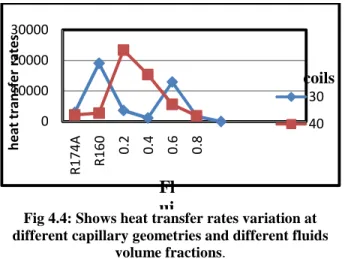
Fig 4.4: Shows heat transfer rates variation at different capillary geometries and different fluids
volume fractions.
The above fig shows the variations of heat transfer rate between the 30, 40 coils geometries with different fluids. It is observed that the heat transfer rate is maximum at 40 coils with 0.2 volme fraction.
5. CONCLUSION
It is found that R174A in capillary tube of 40 coils has more heat transfer coefficient.
It is observed that heat transfer rate is higher at 0.2 volume fraction fluid in 40 coils capillary tube, when compared to remaining fluids in 30&40 coils.
It is observed that R174A is the better fluid as it has more heat transfer co efficient.
When compared with the capillary tube models of 30 coil and40 coils, it is found that 40 coil capillary tube has high heat transfer co efficient.
FUTURE SCOPE
The present CFD analysis consist of mixed refrigerants used in capillary tube with different number of coils(30&40coils). In this analysis,determined the heat transfer coefficient, mass flow rates and pressure drop. There is a scope of future analysis with different types of refrigerants like azeotropes and mixed refrigerants for determine heat transfer coefficient, mass flow rates and should reduce power consumption to increase coefficient of perforce.
REFERENCES
[1]. Hirendra Kumar Paliwall, Keshav Kant" A model for helical capillary tubes for refrigeration systems," International Refrigeration and Air Conditioning Conference Purdue University , 2006
[2]. Shashankshekharpathak, Prakharshukla, Sanjeevchauhan, “Effectof capillary tube on the performance of a simple vapourcompression refrigeration system”, International Organisation of Scientific Research - Journal of Mechanical and Civil Engineering (IOSR–JMCE), 2014.
[3]. M.Y.Taib, A.A.Aziz and A.B.S.Alias, “Performance analysis of a domestic refrigerator”, National Conference in Mechanical Engineering Research and Postgraduate Students, 2010.
[4]. Sanggoon Park, Kidong Son, JihwanJeong and Lyunsu Kim, “Simulation of the effects of a non -adiabatic capillary tube on refrigeration cycle”, International Refrigeration and Air Conditioning Conference, 2008
[5]. SudharashBhargava and Jagdev Singh, “Experimental study of azeotropic blend(30% propane, 55% n-butane, 15% iso-butane) refrigerant flow through the serpentine capillary tube in vapour compression refrigeration system”, International Journal of Mechanical and Production Engineering Research and Development, 2013.
[6]. Ankush Sharma and Jagdev Singh, “Experimental investigation of refrigerant flow rate with spirally coiled adiabatic capillary tube in vapour compression refrigeration cycle using eco friendly refrigerant”, International Journal of Mechanical and Production Engineering Research and Development, 2013.
[7]. Akash Deep Singh, "Flow characteristics of refrigerant inside diabatic capillary tube," Thapar University, Patiala, (2009), pp. 1-96.
0 10000 20000 30000
R174A R160
0.2 0.4 0.6 0.8
he
at
tr
an
sf
er
rat
es
coils
30 40