Abstract—The advantages of microstrip antennas have made
them a perfect choice for use in the wireless local area network (WLAN) applications. Though bound by certain disadvantages, Microstrip patch antennas can be tailored to be used in the new high speed broadband WLAN systems. This paper concentrates on design ofmicrostrip patch antennas for the 2.4 GHz ISM band. The aim of this paper is to present, a coaxial feed compact rectangular antenna with slots, with linear polarization for multibandband operation.A rectangular antenna is loaded with a square slots and U-slot to obtain multiband band operation. The resulted antenna can be simulated using IE3D software which uses a numerical technique called method of moments. By properly selecting the dimensions of the slots, a four band resonance operation of the antenna at 2.23 GHz, 4.1GHz. 4.9GHz and 5.3GHz are achieved. The coaxial feed for this rectangular patch antenna is placed along the x-axis for 50 ohms impedance matching. All the four resonant bands have moderate bandwidth, acceptable radiation characteristics and efficiency. Different parameters of antenna like return loss, efficiency, 2 dimensional and 3 dimensional radiation patterns are simulated using IE3D software.
Index Terms—— Antenna, linear Polarization, Dual band,
IE3D, Linear Polarization, Microstrip, Multiband, Probe feed, Rectangular, Slots.
I. INTRODUCTION
Thispaper concentrates on study of Microstrip patch antenna, types of polarization, different methods to obtain dual band operation and multiband operation and types of feeds used for feeding microstrip patch.
The Microstrip antenna has advantages such as low cost, lightweightand portability. To overcome its main disadvantage of narrow bandwidth, several methods have been proposed to enhance bandwidth such as loading Microstrip antenna with different types of slots e.g.:- U-slot, C-slot, L-slotetc. [1]-[6] or by feeding the Microstrip patch with different types of feed [7].
A patch antenna basically consists of a rectangular patch whose length (L) and Width (W) of the patch is calculated by design equations. The patch is usually made of copper.
In this design we are concentrating on rectangular patch antenna, however the patch antenna can be designed for any shape depending on their respective equations based on circular patch, triangular patch, etc. The patch antenna can be fed by various types of feed, such as co-axial probe feed, Microstrip feed, inset feed, proximity feed etc., but here we are using probe feed for feeding rectangular microstrip patch
antenna, as it is having an advantages of placing probe feed in any location of patch[7].
A Microstrip patch antenna can work in linear polarization and circular polarization mode, depending upon where the location of feed was placed[7][8]. Here we are using linear polarization for achieving multiband operation.
A single feed, linearly polarized, rectangular Microstrip antenna have been discussed in this paper for multi band operation by loading a square slots and U-slot in the patch.
II. PROCEDURE FOR ANTENNA DESIGN
A. Design Equations
The geometry of the multi band linearly polarized antenna is shown in Fig1. It consists of rectangular patch with dimensions (L X W). The rectangular patch is separated from ground plane with a FR4 substrate (ε =4.8) of thickness h=1.56 mm.
Fig1. Geometry of proposed antenna
The Width (W) of the Microstrip patch is found by using the equation (1).
𝑊 =
𝑐2𝑓√𝜀 (1)
Where, „c‟ is the velocity of light. „f‟ is the designed frequency in GHz. „Ɛ‟ is the dielectric constant of the material.
The Length (L) of the Microstrip patch is calculated by the equation(2).
𝐿 =
2𝜀𝑒𝑓𝑓𝑐− 2∆𝑙
(2)Design of Multiband Microstrip Antenna
Nazahat Jahan Balur, Sardar Patel Institute of Technology, Mumbai University, Mumbai, India.
Volume 1, Issue 10, December 2012
83 Where, „εeff‟ is the effective dielectric constant.
„L‟ is the actual patch length and „∆l’ is the extension length and can be calculated from equation (3).
∆𝑙 =
𝜀𝑒𝑓𝑓 −0.258𝜀𝑒𝑓𝑓 +0.3∗
(𝑊 ℎ+0.264)
(𝑊ℎ +0.8) (3)
Where, „h‟ is the height of the dielectric substrate which is equal to 1.56mm.
𝜀𝑒𝑓𝑓 =
𝜀+12+
𝜀−12∗
1√( 1+10ℎ𝑊 ) (4)
B. Design Parameters and simulation
A substrate of thickness 1.56mm, width and length of the patch as 38mm and 29mm respectivelywere considered based on the designdimensions. The operating frequency of the proposed antenna is 2.4GHz. In this work, co-axial or probe feed technique is used as its main advantage is that, the feed can be placed at any place in the patch to match its input impedance (usually 50ohms). A patch with a single coaxial feed was resonating at 2.23GHz with moderate return loss and narrow bandwidth; the square slots have been loaded in the patch to make the return loss more negative for perfect transmission with least reflection of the signals. The slots introduces capacitive effect which nullifies the inductive effect of the probe, this increases return loss and bandwidth. The U- slot in the patch adds the multi resonant frequency so that the antenna operates in more than two frequencies; hence a multiband operation is achieved. The square slot at the top corners makes the return loss more negative of the bands other than 2.23GHz band. IE3D software is used to model antenna and plot return loss, VSWR, radiation pattern, smith chart and various other pattern.IE3D divides the antenna geometry into meshbased on method of movements.
C. Feed Point Location
A coaxial probe type feed is used in this design. The center of the patch is taken as the origin and the feed point location is given by the co-ordinates (X, Y) from the origin. The feed point must be located at that point on the patch, where the input impedance is 50 ohms for the resonant frequency. A trial and error method is used to locate the feed point. The return loss is compared for different locations of the feed point and the feed point is selected where the return loss is most negative and impedance match of 50ohms is obtained with +/- 5% error.
III. RESULTS OBTAINED
The Square slot microstrip patch antenna designed on Electro Magnetic simulator software IE3D and after simulation reflection coefficient S11 is obtained. We have design operating frequency for antenna as 2.4GHz, but after simulation resonance frequency shifted at 2.23GHz, with return loss of 30dB.
Return loss is a parameter which indicates the amount of power that is “lost” to the load and does not return as a reflection. Hence the return loss is a parameter to indicate how well the matching between the transmitter and antenna has taken place, indicated as S11 of an antenna. For optimum working return loss graph must show a dip at the operating
frequency and have a minimum dB value at this frequency. Fig 2 shows the return loss versus frequency graph. It is seen that the antenna is operating in 4bands that is at 2.23GHz, 4.1GHz, 4.9GHz and 5.3GHz which has a return loss of -30dB, -21.4dB, -20.33dB and -16.99dB respectively.
Fig 2. Return loss vs. frequency in GHz
The characteristic impedance is an important parameter for obtaining resonance by matching the feed to 50 ohms of antenna. As the frequency increases the fields are more confined to the substrate which decreases effective width and hence characteristic impedance decreases. For the fundamental mode TM10mode, since the voltage is maximum and current is minimum at the edges the input impedance of the rectangular Microstrip antenna varies from zero value at its center to the maximum value at the radiating edges. To obtain impedance matching with the co-axial feed, the feed point should be placed where the input impedance of the antenna matches the characteristic impedance of the feed line. Fig 3 shows the impedance values with respect to the frequency at all the four resonating bands.
Fig3. Real value of impedance vs. frequency in GHz
The Voltage Standing Wave Ratio (VSWR) ratio also indicates the impedance matching between load and the feed line. VSWR should be equal to 1 ideally but practically it should be less than 1.5 for good operation of antenna. Fig 4 shows the graph of VSWR with respect to the frequency for all the four resonating bands.
Fig 4. VSWR vs frequency graph
The designed antenna operates in 4 bands, the bandwidth of the each band can be found at the point the VSWR is below 1.5 or it can also be found from the return loss graph where the return loss is below -9.8db. Here we have found the bandwidth of all the bands i.e., 2.233 GHz, 4.1GHz, 4.9GHz and 5.3GHz as 48.64MHz, 48.4MHz, 68.4MHz and 50.8MHz respectively.
The one more antenna parameter is its radiation pattern, which is a graphical representation of radiation properties of the antenna as the function of space co-ordinates [8].
Fig5 shows the radiation pattern of antenna at 2.23GHz, Fig 6 shows radiation pattern at 4.1GHz, Fig 7 shows radiation pattern at 4.7GHz and Fig 8 shows radiation pattern at 5.3GHz.
Fig5. Radiation pattern at 2.23GHz
Fig6. Radiation pattern at 4.1GHz
Volume 1, Issue 10, December 2012
85 Fig8. Radiation pattern at 5.3GHz.
It‟s seen from all radiation patterns that the pattern at 2.23 GHz has no side lobes, all the radiation is in main beam direction, hence it is having more negative return loss and good VSWR compare to other resonating bands. Since the other resonating bands have more side lobes, less radiation is in the main beam direction and hence its return loss is less negative.
Radiation pattern can also be viewed in two dimension which is shown in fig 9.
Fig9. Two dimensional radiation patterns for E-total at 00 and 900
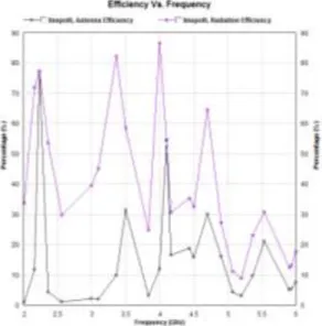
Another important parameter of the antenna is its efficiency;the antenna efficiency and the radiation efficiency. Radiation efficiency describes how effectively radiation is taking place in desired direction, and antenna efficiency describes how effectively the proposed antenna radiates. Fig 10 shows the antenna efficiency and radiation efficiency of the proposed antenna.
Fig 10. Antenna efficiency and radiation efficiency vs. frequency.
When the simulation of the antenna has taken place using IE3D software, at each resonant frequency we get the distribution of current. Fig 11shows the current distribution of the proposed antenna at 2.23GHz.
Fig11. Current distribution at 2.23GHz.
IV. CONCLUSION
advantageous.
ACKNOWLEDGMENT
I would like to extend my gratitude and my sincere thanks to my head of department Prof. Y.S. Rao, for providing me with best facilities in the Department and his timely suggestions.I sincerely thank my guide Prof. Sukanya
Kulkarni, for her exemplary guidance and
encouragement.Finally I extend my special thanks to
Ashfaque Anees for his constant support during my research
work.
REFERENCES
[1] Harshvardhan Tiwari and M.V.Kartikeyan, “Design Studies of Stacked U-Slot Microstrip Patch Antenna for Dual Band operation”,35th international conference on infrared millimeter and terahertz waves.2010
[2] Vedaprabhu and K.J. Vinoy. ”A Double U-slot Patch Antenna with Dual Wideband Characteristic”, A national conference on communication. 2010.
[3] Tran Minh Tuan.”Design of Dual-band Microstrip Monopole Antenna for 3G mobile handset”, Proceedings in international conference on communications and electronics, 2010.
[4] Dinesh Yadav.” L Slotted Rectangular Microstrip Patch Antenna”. An International Conference on Communication Systems and Network Technologies. 2011
[5] Ramesh garg, Prakash bharatia. ”Microstrip antenna design handbook”. Artech House Boston London.2001
[6] Vinod K. Singh, Zakir Ali, Dr Shahanaz Ayub :" Design of Compact Rectangular Slot Micro strip Antenna for Mobile Communication", Global Journal of Researches in Engineering,52 Vol. 10 Issue 7 (Ver 1.0), December 2010
[7] K.P.Ray and Girish Kumar, “Broadband Microstrip Antennas, Artech House Antennas and Propagation Library. 2003.
[8] Balanis, “Antenna Theory Analysis and Design”, John Wiley and sons, Inc, 2nd edition.
Nazahat Jahan Balur
BE (Electronics and Communication),ME (EXTC)-pursuing
Have presented and published a paper entitled “Design of Compact Rectangular Antenna with Square Slots”, at ICWET conference proceedings, 2012.
Achievements: -Won academic excellence awards throughout BE and ME courses.
Prof. Sukanya Kulkarniisan Associate Prof in Electronics and Telecomm