Improvement of Grid Current Compensator in Distributed Generation System
P Govinda Raju1, K Venkata Ramana2M.Tech Scholar, Department of EEE, PCET, Anathavaram, India.1 Asso. Professor, Department of EEE, PCET, Anathavaram, India.2 Abstract— This paper Proposed a new current control
topology for grid-connected based distributed generation (DG), which helps the DG to exchange a sinusoidal current into the utilitygrid despite the distorted grid voltage and nonlinear local load conditions. The proposed current controller is outlined in the synchronous reference casing and made out of a Fuzy controller. Consequently, the control methodology can be incredibly rearranged effectively. What's more, the proposed control strategy does not require the nearby load current estimation or symphonious investigation of the framework voltage. In this manner, the proposed control technique can be effectively embraced into the conventional DG control framework without establishment of additional equipment. In spite of the lessened number of sensors, the framework current quality is altogether progressed. The operation standard of the proposed control technique is examined in detail, and its viability is approved through watching absolute symphonious bending (THD) and the results verified through MATLAB/SIMULINK environment.
Index Terms—Distributed generation (DG), Fuzzy controller, grid-connected inverter, harmonic compensation, nonlinear load, repetitive control.
I. INTRODUCTION
Circulation era units prevalently Renewable vitality sources, for example, wind turbines, photovoltaic, and power devices, has significantly expanded in late decades to address worries about the worldwide vitality emergency, exhaustion of fossil fills, and ecological contamination issues. Matrix Current Compensator for Grid-Connected Distributed Generation under direct and non straight load condition are dissected with PI-RC controller in [1] and the operational perceptions demonstrate the effectiveness of the controller sharply. Therefore, an expansive number of renewable vitality sources have been coordinated in power circulation frameworks as disseminated era (DG) [2]. DG frameworks can offer many focal points over customary power era, for example, little size, minimal effort, high effectiveness, and clean electric power era. A DG framework is ordinarily worked in a network associated mode where the most extreme accessible power is removed from vitality sources and exchanged to the utility matrix
[3]-[9]. Likewise, to abuse full points of interest of a DG framework, the DG can be additionally furnished and worked with neighborhood loads, where the DG supplies energy to the nearby load and exchanges surplus energy to the lattice [10]-[15]. In both setups, i.e., with and without the nearby load, the prime target of the DG framework is to exchange an amazing current (matrix current) into the utility lattice with the constrained aggregate consonant bending (THD) of the network current at 5%, as suggested in the IEEE 1547 measures [16].
To deliver a top notch framework present, different current control procedures have been presented, for example, hysteresis, prescient, corresponding fundamental (PI), and relative full (PR) controllers. Hysteresis control is basic and offers quick reactions; be that as it may, it routinely creates high and variable exchanging frequencies, which brings about high current swells and troubles in the yield channel outline [4]. In the interim, prescient control is a feasible answer for current direction of the matrix associated DG. In any case, notwithstanding its fast reaction, the control execution of the prescient controller firmly depends on framework parameters [5]. Accordingly, framework instability is a critical issue influencing the network current quality. The PI controller in the synchronously turning (d-q) reference
outline and the PR controller in the stationary (α-β)
matrix current quality in this manner depends intensely on the precision of the framework voltage consonant examination; if the symphonious parts in the network voltage are fluctuated, it is hard to keep up a decent lattice current quality. Additionally, the looking calculation requires an extensive figuring time and can work just disconnected. A few particular symphonious compensators are produced utilizing a full controller, in which the resounding controller tuned at the 6th different of the principal recurrence is added to take out the impact of fifth and seventh consonant framework voltages on the lattice current quality. The network current quality can be enhanced, because of the extra full controllers. Be that as it may, if higher request music are considered, more thunderous controllers ought to be included in light of the fact that a solitary resounding controller can manage just a single particular consonant segment [8], [9]. Tragically, including more controllers builds the multifaceted nature of the control framework. To enhance the network current quality with a streamlined control conspire, the redundant control system has been embraced [13]. A dreary controller (RC) serves as a bank of full controllers to repay countless segments with a basic postpone structure. In any case, in spite of the adequacy of the RC in symphonious remuneration, the customary RC has a long postpone time, which routinely constrains the dynamic reaction of the present controller. For instance, as reported in [13], the dynamic reaction of the framework current under a stage change of the present reference is roughly 150 ms, which is to a great degree moderate contrasted and other control techniques. Also, even with the usage of the RC, this technique can't bring the THD of the matrix current lower than the constrained esteem 5% in the IEEE 1547 benchmarks. Alongside matrix voltage mutilation, the nearness of nonlinear loads in the nearby heap of the DG likewise causes a negative effect on the lattice current quality [14]. To address this issue, the nearby load current estimation and a heap current feedforward circle are routinely received [14], [15]. In spite of the fact that these pay techniques are successful in enhancing matrix current quality, the prerequisite of extra equipment, particularly the present sensor for measuring the neighborhood stack current, is the fundamental downside of this control strategy. Moreover, most previously mentioned reviews consider and independently handle the effect of contorted network voltage or the nonlinear neighborhood stack; none of them at the same time considers those issues.
To defeat the confinements of previously mentioned reviews, this paper proposes a propelled current control system for the framework associated DG, which makes the network current sinusoidal by at the same time killing the impact of nonlinear nearby load and matrix voltage twists. To begin with, the impact of the matrix outlined in the d-q
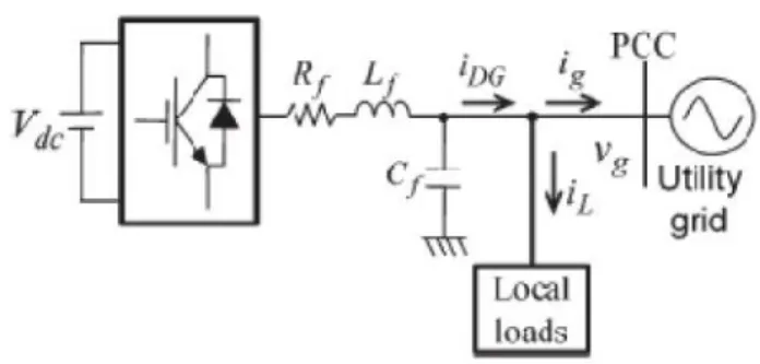
Fig. 1. System configuration of a grid-connected DG system with local load.
One single RC can compensate a large number of harmonic components with a simple delay function. Hence, the control strategy can be greatly simplified. Another advantage of the proposed control method is that it does not demand the local load current measurement and the harmonic analysis of the grid voltage. Therefore, the proposed control method can be easily adopted into the traditional DG control system without the installation of extra hardware. Despite the reduced number of sensors, the performance of the proposed grid current controller with fuzzy technique is significantly improved compared with that of the PI current controller. In addition, with the combination of fuzzy, the dynamic response of the proposed current controller is also greatly enhanced compared with that of the traditional PI-RC. The feasibility of the proposed control strategy is completely verified by simulation results.
II. SYSTEM CONFIGURATION AND ANALYSIS OF GRID VOLTAGE DISTORTION AND NONLINEAR
LOCAL LOAD
Fig. 1 demonstrates the framework setup of a three-stage DG working in lattice associated mode. The framework comprises of a dc control source, a voltage-source inverter (VSI), a yield LC channel, neighborhood loads, and the utility lattice. The reason for the DG framework is to supply energy to its neighborhood stack and to exchange surplus energy to the utility network at the PCC. To ensure brilliant power, the present that the DG exchanges to lattice (ig ) ought to be adjusted, sinusoidal, and have a low THD esteem. Notwithstanding, on account of the twisted lattice voltage and nonlinear neighborhood stacks that regularly exist in the power framework, it is difficult to fulfill these necessities.
A. Impact of Grid Voltage Distortion
current (ig ) to the utility lattice (vg ). For rearrangements reason, it is expected that the nearby load is not associated into the framework. In Fig. 2(a), the voltage condition of the framework is given as
(1) whereRf andLf are the equivalent resistance and inductance of the inductorLf, respectively.
Fig. 2. Model of grid-connected DG system under distorted grid voltage condition.
(a) General condition;
(b) at the fundamental frequency; and (c) at harmonic frequencies.
If both the inverter voltage and the grid voltage are composed of the fundamental and harmonic components as (2), the voltage equation of (1) can be decomposed into (3) and (4), and the system model shown in Fig. 2(a) can be expressed as Fig. 2(b) and (c), respectively. That is
B. Effect of Nonlinear Local Load
Fig. 3 shows the model of a grid-connected DG system with a local load, whereby the local load is represented as a current source iL, and the DG is represented as a controlled current source iDG. According to Fig. 3, the relationship of DG current
iDG, load current iL, and grid current ig is described as
Fig. 3. Model of grid-connected DG system with nonlinear local load.
Assuming that the local load is nonlinear, e.g., a three-phase diode rectifier, the load current is composed of the fundamental and harmonic components as
where iL1 and iLh are the fundamental and harmonic
compo-nents of the load current, respectively. Substituting (6) into (5), we have
From (7), it is obvious that, in order to transfer sinusoidal grid current ig into the grid, DG current iDG should include the harmonic components that can compensate the load current
harmonics Therefore, it is important to design an effective and low-cost current controller that can generate the specific harmonic components to compensate the load current harmonics. Generally, traditional current controllers, such as the PI or PR controllers, cannot realize this demand because they lack the capability to regulate harmonic components.
III. PROPOSED CONTROL SCHEME
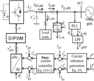
To enhance grid current quality, an advanced current control strategy, as shown in Fig. 4, is introduced. Although there are several approaches to avoid the grid voltage sensors and a phase-locked loop (PLL) [19], Fig. 4 contains the grid voltage sensor and a PLL for simple and effective implementing of the proposed algorithm, which is developed in the d-q reference frame.
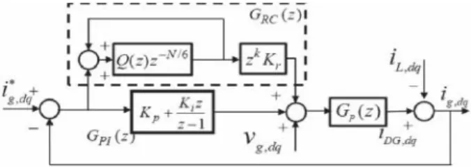
Fig. 5. Block diagram of the current controller. The proposed control scheme is composed of three main parts: the PLL, the current reference generation scheme, and the current controller. The operation of the PLL under distorted grid voltage has been investigated, in detail, in [20]; therefore, it will not be addressed in this paper. As shown in Fig. 4, the control Fig. 6. Bode diagram of the
voltage analysis on the grid voltage. Therefore, it can be developed without requiring additional hardware. Moreover, it can simultaneously address the effect of nonlinear local load and distorted grid voltage on the grid current quality .
A. Current Reference Generation
As shown in Fig. 4, the current references for the current controller can be generated in the d-q reference frame based on the desired power and grid voltage as follows [15]:
where P ∗ and Q∗ are the reference active and reactive power, respectively; vgd represents the instantaneous grid voltage in the d-q frame; and igd and igq denote the direct and quadrature components of the grid current, respectively.Under ideal conditions, the magnitude of vgd has a constant value in the d-q reference frame because the grid voltage is pure sinusoidal. However, if the grid voltage is distorted, the magnitude of vgd no longer can be a constant value. As a consequence, reference current igd and igq cannot be constant in (8). To overcome this problem, a low-pass filter (LPF) is used to obtain the average value of vgd , and the d-q reference currents are modified as follows, whereVgd0 is the average value of vgd, which is obtained through the LPF in Fig. 4
IV. Fuzzy controller
The word Fuzzy means ambiguity. Fuzziness happens when the limit of bit of data is not obvious. In 1965 Lotfi A. Zahed propounded the Fuzy set hypothesis. Fuzy set hypothesis shows monstrous potential for viable unraveling of the vulnerability in the issue. Fuzy set hypothesis is an astounding scientific apparatus to handle the vulnerability emerging because of dubiousness. Understanding human discourse and perceiving written by hand characters are some normal occasions where fluffiness shows.
FLC the information factors are mapped by sets of enrollment capacities and these are called as "Fuzy SETS".
Fuzy set contains from a participation capacity which could be characterizes by parameters. The esteem somewhere around 0 and 1 uncovers a level of participation to the Fuzy set. The way toward changing over the fresh contribution to a Fuzy esteem is called as "fuzzificaton." The yield of the Fuzzier module is interfaced with the standards. The fundamental operation of FLC is developed from Fuzy control rules using the estimations of Fuzy sets all in all for the mistake and the change of blunder and control activity. Essential Fuzy module is appeared in fig.6.
The outcomes are joined to give a fresh yield controlling the yield variable and this procedure is called as "DEFUZZIFICATION."
Fig.6. Fuzzy Basic Module i. Fuzzy rules
In the fuzzy control, input and output variables are the size of the form to describe in words, so to select special vocabulary to describe these variables, generally used in "big, medium and small" Three words to express the controller input and output variables state, plus the positive and negative directions, and zero, a total of seven words : { negative big, negative medium, negative small, zero, positive small, middle, CT } , the general terms used in the English abbreviation prefix : {NB , NM, NS , ZE, PS , PM, PB}.
COE
E
NB NM NS ZE PS PM PB
NB NB NB NB NB NM NS ZE
NM NB NB NB NM NS ZE PS
NS NB NM NS NS ZE PS PM
ZE NB NM NS ZE PB NS ZE
PS NM NS ZE PS PM PM PB
PM NS ZE PS PM PB PB PB
PB ZE PS PM PB PB PB PB
ii. Membership Functions
A membership function (MF) is a curve that defines how each point in the input space is mapped to a membership value (or degree of membership) between 0 and 1. A membership function for a fuzzy set A on the universe of discourse X is defined as µA: X → [0,1], where each
element of X is mapped to a value between 0 and 1. This value, called membership value or degree of membership, quantifies the grade of membership of the element in X to the fuzzy set A. Membership functions allow us to graphically represent a fuzzy set. The x axis represents the universe of discourse, whereas the y axis represents the degrees of membership in the [0,1] interval. Simple functions are used to build membership functions. Because we are defining fuzzy concepts, using more complex functions does not add more precision. Below is a list of the membership functions we will use in the practical section of this tutorial. Triangular function: defined by a lower limit a, an upper limit b, and a value m, where a < m < b.
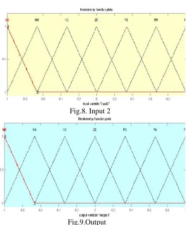
Fig.8. Input 2
Fig.9.Output
Membership functions plots, Fig.7, Fig.8, Fig 9 are the input 1, input2 and output of fuzzy controller respectively. These plots are obtained according to the rules written in the fuzzy tool box and the switching process depends upon these rules.
TABLE I SYSTEM PARAMETERS
V. SIMULATION RESULTS
A simulation model of the DG system is built by MATLAB/Simulink software to verify the effectiveness of the proposed control method. The system parameters are given in Table I. In the simulation, three cases are taken into account.
load is used.
2) Case II: The grid voltage is sinusoidal and the nonlinear local load is used.
3) Case III: The grid voltage is distorted and the nonlinear local load is used.
In Cases I and II, the grid voltage is assumed as a pure sinusoidal waveform. In Case III, the distorted grid voltage is supplied with the harmonic components: 3.5% 5th harmonic, 3% 7th harmonic, 1% 11th harmonic, and 1% 13th harmonic. The THD of grid voltage is about 4.82%. This grid voltage condition complies with the IEEE 519-1992 harmonic restriction standards, where the THD of grid voltage is less than 5% . In all test cases, the reference grid current is set at igd = 10 A and igq = 0, and the fuzzy current controller is investigated to compare its control performances.
(a)
(b)
(c)
Fig. 10. Simulation results with the PI current controller:
(a) Case I; (b) Case II; and (c) Case III.
TABLE II
SUMMARY OF THD VALUES OF GRID CURRENT WITH
PI AND PROPOSED CURRENT CONTROLLERS PI & RC current
controller
FUZZY LOGIC current controller Case
I
Case II
Case III
Case I
Case II
Case III TH
D Of ig
1.55 %
1.80 %
1.92 %
1.23 %
1.61 %
1.76 %
VI. CONCLUSION
the dynamic response of the grid current controller was also greatly enhanced compared with that of the traditional PI-RC topology and fuzzy controller.
REFERENCES
[1] Quoc-Nam Trinh, Hong-Hee Lee, “An Enhanced Grid Current Compensator for Grid-Connected Distributed Generation Under Nonlinear Loads and Grid Voltage Distortions,” IEEETRANS.Ind.Electronics, vol. 61, no. 12, pp. 6528-6537, Dec. 2014.
[2] R. C. Dugan and T. E. McDermott, “Distributed generation,” IEEE Ind.Appl. Mag., vol. 8, no. 2, pp. 19-25, Mar./Apr. 2002.
[3] F. Blaabjerg, R. Teodorescu, M. Liserre, and A. V.
Timbus, “Overviewof control and grid synchronization
for distributed power generation systems,” IEEE Trans.
Ind. Electron., vol. 53, no. 5, pp. 1398-1409,Oct. 2006. [4] J. A. Suul, K. Ljokelsoy, T. Midtsund, and T.
Undeland, “Synchronous reference frame hysteresis
current control for grid converter applications,” IEEE Trans. Ind. Appl., vol. 47, no. 5, pp. 2183-2194, Sep./Oct. 2011. [5] Q. Zeng and L. Chang, “An advanced SVPWM-based predictive current controller for three-phase inverters in
distributed generation systems,”IEEE Trans. Ind. Electron., vol. 55, no. 3, pp. 1235-1246, Mar. 2008.
[6] S. Buso and P. Mattavelli, “Digital control in power electronics,” in Synthesis Lectures on Power Electronics. San Rafael, CA, USA: Morgan & Claypool, 2006.
[7] C. A. Busada, S. Gomez Jorge, A. E. Leon, and J. A.
Solsona, “Current controller based on reduced order
generalized integrators for distributed generation systems,”
IEEE Trans. Ind. Electron., vol. 59, no. 7, pp. 2898- 2909, Jul. 2012.
[8] M. Liserre, R. Teodorescu, and F. Blaabjerg, “Multiple
harmonics control for three-phase grid converter systems with the use of PI-RES current controller in a rotating
frame,” IEEE Trans. Power Electron., vol. 21, no. 3, pp. 836-841, May 2006.
[9] M. Castilla, J. Miret, A. Camacho, J. Matas, and L. G.
de Vicuna, “Reduction of current harmonic distortion in three-phase grid-connected photo voltaic inverters via
resonant current control,” IEEE Trans. Ind. Electron., vol. 60, no. 4, pp. 1464-1472, Apr. 2013.
[10] R.-J. Wai, C.-Y. Lin, Y.-C. Huang, and Y.-R. Chang,
“Design of high-performance stand-alone and grid-connected inverter for distributed generation
applications,” IEEE Trans. Ind. Electron., vol. 60, no.
4,pp. 1542-1555, Apr. 2013.
[11] I. J. Balaguer, Q. Lei, S. Yang, U. Supatti, and F. Z.
operations of distributed power generation,” IEEE Trans.
Ind. Electron., vol. 58, no. 1, pp. 147-157,Jan. 2011. [12] G. G. Pozzebon, A. F. Q. Goncalves, G. G. Pena, N. E. M. Mocambique, and R. Q. Machado, “Operation of a three-phase power converter connected to a distribution
system,” IEEE Trans. Ind. Electron., vol. 60, no. 5, pp. 1810-1818, May 2013.
[13] Q.-C. Zhong and T. Hornik, “Cascaded current-voltage control to improve the power quality for a grid-connected
inverter with a local load,” IEEETrans. Ind. Electron., vol. 60, no. 4, pp. 1344-1355, Apr. 2013.
[14] Z. Yao and L. Xiao, “Control of single-phase
grid-connected inverterswith nonlinear loads,” IEEE Trans. Ind.
Electron., vol. 60, no. 4, pp. 1384-1389, Apr. 2013.
[15] Z. Liu, J. Liu, and Y. Zhao, “A unified control strategy
for three-phase inverter in distributed generation,” IEEE
Trans. Power Electron., vol. 29,no. 3, pp. 1176-1191, Mar. 2014.